Starting a control box build

Homebrew Talk - Beer, Wine, Mead, & Cider Brewing Discussion Forum

Help Support Homebrew Talk - Beer, Wine, Mead, & Cider Brewing Discussion Forum:

This site may earn a commission from merchant affiliate links, including eBay, Amazon, and others.

Gonefishing

Someday I'll stop procrastinating
Joined
Oct 28, 2008
Messages
968
Reaction score
80
Location
Bridgton
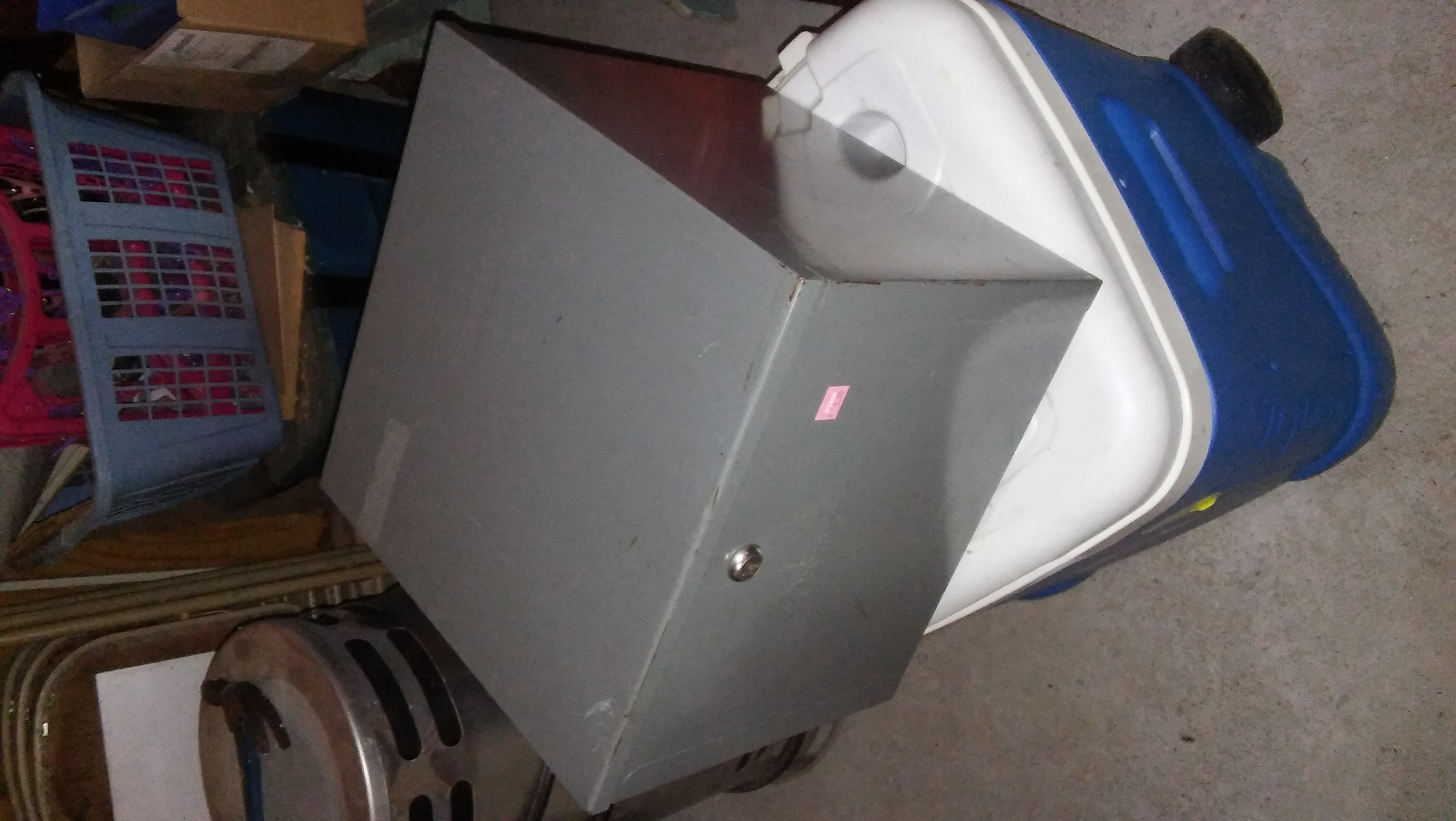
I picked up this box today at the Goodwill store. It's a bit deep, but it's sturdy metal and at $6 I couldn't leave it sitting there.
I think I might add some sliding shelves to put the components on because the box is 13 inches deep... which is also the height and width. In its original incarnation, it was a file box.
box.jpg
 
You drill holes in the back, put bolts and nuts on the front side and another piece of metal to give you about 1/2" of space between the box and your electronics. You could mount a DIN rail and be off to the races.
 
I would love to do it that way, but I already bought the internals...and I'm extra cheap. Sure is organized looking though.
 
Just let the smoke out of my new 120mm fan I bought to cool the SCR for the boil kettle...the replacement fan will be here Monday.
 
Just let the smoke out of my new 120mm fan I bought to cool the SCR for the boil kettle...the replacement fan will be here Monday.

Do you know why the first fan went up in smoke? And, what are you going to do differently to prevent the new fan from going the way of the first.

Brew on :mug:
 
Oh, I know...I was stupid. There are three wires on the fan so I decided to just touch wires to the power supply until it ran. Turns out that many of the reviews on this fan clearly state that reversing the polarity smokes the motor. As a result of reading those reviews I now know which wires is which so I won't make this same mistake again.
 
New fan is in and runs fine now that it's wired correctly.
I got to the point of about 90% completion and decided that I needed to make some changes. Today I took it almost entirely apart to make those changes and add a few things. Things like an SSR on each leg of the power wires to the 220 sockets, an SSR that shuts off the 110V circuit when the E-stop button is pressed, a second fan, a fuse to the PIDs, and a general rewiring. I took some pictures, but my phone has decided that it can't send pictures on my home network lately, so they're pending.
I feel much better about this box's safety factor now. I'm anxious to use the brewery as my keg kicked yesterday and I hate buying commercial beer when I don't have to.

You may feel better about the safety factor, but I don't. an E-stop should always cause a mechanical disconnect of any line voltages. An SSR is not a mechanical disconnect, and is unsuitable for a safety disconnect because SSR's most often fail in the on state. SSR's also have enough leakage to give you a pretty good shock, even when they are off.

Also, an SSR on each hot leg of a 240V circuit is wasteful. As noted above, SSR's should never be used as safety switches. All they really do is cut off most (almost all) of the current to turn the power off to loads (elements, etc.) Since current flows in a loop, you only need to break the loop in one place for power control. Using two increases your component cost, increases your probability of failure, and increases the amount of heat (wasted power) created by the SSR's. Using two will still work, but is not good practice.

I'm not trying to pick on you, I just don't want anyone reading this to assume what you have done is good practice. If you would like any help redesigning your system, let me know. I have helped many others with their designs.

Brew on :mug:
 
As Doug has helped me 1000 times over. I built my whole unit in about a week or two with his help in design. Thanks again Doug for being such an active and contributing member. I recommend following his advice. Safety was important to me and he helped a lot with that.
 
Doug, I've read a lot of your posts here and have noted that you always give good sound advice. So I thought I'd address your very valid concerns. Sorry I haven't done so sooner, but I just saw your reply.
The way it is wired now is a contactor on both the 220V and 120V lines. The E-stop kills the 24v that powers the coil on the contactors, so all goes off with that. Beyond the attachment to the "hot" side of the contactors there is no power anywhere in the box when it is off.
My thinking behind an SSR on both legs of the 220V is that should one of them fail the element will still go off. It is my understanding that SSRs generally fail in the "on" state. Though I was at first thinking of the SSR shutting off the 120V power I decided against that and going with a contactor when I read someone's post about SSR's tendency to fail in the on state.

Ok, that sounds better safety wise. SSR's on both hot legs of the 240 won't hurt anything, just waste a little more heat, so as long as you have adequate cooling for the SSR's, you're fine.

Brew on :mug:
 
There's a 120mm fan blowing in on the side, directly over the SCR boil element control, and an 80mm fan also blowing in across the ssrs and contactors. Air can exit through the bottom where I drilled 32 3/4 inch holes to vent the box. Hopefully that is adequate.
 
Progress on the build is once again at a stand still while I wait for parts. I decided that the K-type thermocouples had to go because I wanted the ability to disconnect the cables from the box, so I ordered RTD cables and XLR disconnect sets. They should be here soon and then I can get back to work.
 
I did the exact same thing. I got trigger happy and didn't do enough research. I returned mine to Auber for an RTD. I want to see how your control box comes along. keep posting pictures!
 
Well, here we are a year and a half later and I still haven't finished this build. Yesterday I got everything out of the storage spots where I'd stashed it all and started assembling the brewery with the intention of doing a test run today. Laziness kicked in and I didn't work on it at all today. I have all the ingredients for a brew waiting for me to get this going, so tomorrow morning I'll be out in the garage working on this thing. I need to run a 120v line, plumb for the pump and put the temp sensors in and calibrate (as if I knew how) the controllers. Then it's a test run, and then, hopefully, a brew day.
 
Well, hopefully, today i the test day. I need to install the rtd's (my soldering equioment, and talents, aren't up to using the mini-xlr connectors I bought, so they'll be wired to the controllers directly), the tubing and the pump(s). I have two pumps, but the second one is 220v (should have read the ebay ad better) so I don't think I'm going to use it. Hoping for a water test this afternoon. Should have been yesterday but it snowed so I was a taxi driver for my wife all day. Wish me luck.
 
I did get to test the system today, after some finishing touches. I discovered that one of my PIDs doesn't have the 3rd terminal for an RTD, so that one is just a thermocouple, but that works fine because all my RTDs are long ones, and the K-type is short and fits fine. I want to measure the temp of the wort as it's recirculated so I drilled and taped a fitting for the termocouple to fit in. I haven't tested it with water yet and I am afraid it will leak, but further testing tomorrow will tell. At this point, I can say the control box powers up and the boil element works as it should. I could not test the HERMS tank because at some point during the last year I stole its power cord for some other project. Made a trip to Home Depot tonight and bought a new cord ( I couldn't find a 3-wire cord here to save my soul!) so tomorrow I'll get that setup and tested too.
One of the problems with putting a project aside for about a year when you're 69 is that some details get forgotten... so when I fired this baby up this morning nothing happened. I spent about an hour looking for a multimeter and suddenly remembered this thing has TWO power cords...one for 110v and one for 220v. I had not plugged the smaller voltage cord in! After plugging it in I hit the "start" button to energize the main relay, but as soon as I took my finger off th switch button the box went off again. Took me a minute to remember that in addition to the start button there is a power switch. After turning that on the main relay stayed energized as it should. I also could not find my notes and hadn't labeled a thing so it took some wire-chasing to remember how I'd put this thing together.
There will be pictures after it's all setup and cleaned up.
 
Well, I discovered that it's a good thing water is cheap (actually, I have a well) because the heat exchanger had just a few leaks. The major one...actually two... was that the copper tubing had split in two places and quickly overfilled the container. Took it all apart to solder the leaks shut, put it back together and couldn't stop the leaks where the fittings passed through the container sides. Two trips to the hardware store...and changed my design so no more leaks.
Decided to do an evaporation test on the boil, so I put 5 gallons of water in the BK and fired it up. Came to a boil with my cold well water in 18 minutes. After it came to the boil I started dialing down the power to the element, and found that a good boil is maintained at 50% power. It's cooling a bit now, but I'll go back out and see how much water I have left in a minute or so.
Ok, it's later now. It boiled off 1.75 gallons in one hour.
Tonight I will test the Herms for hour or so after dinner.
 
Back
Top