soldering XLR to RTD PT100

Homebrew Talk - Beer, Wine, Mead, & Cider Brewing Discussion Forum

Help Support Homebrew Talk - Beer, Wine, Mead, & Cider Brewing Discussion Forum:

This site may earn a commission from merchant affiliate links, including eBay, Amazon, and others.

kokonutz

Well-Known Member
Joined
May 5, 2020
Messages
73
Reaction score
9
Location
Campbell River
Hi - I have this thermocouple (image below...2 blue, one red) - I was reading this post and realize I need some more clarity. Both my XLR female connector and male receptacle have labels 1,2, and 3 respectively for each prong. My plan is/was:
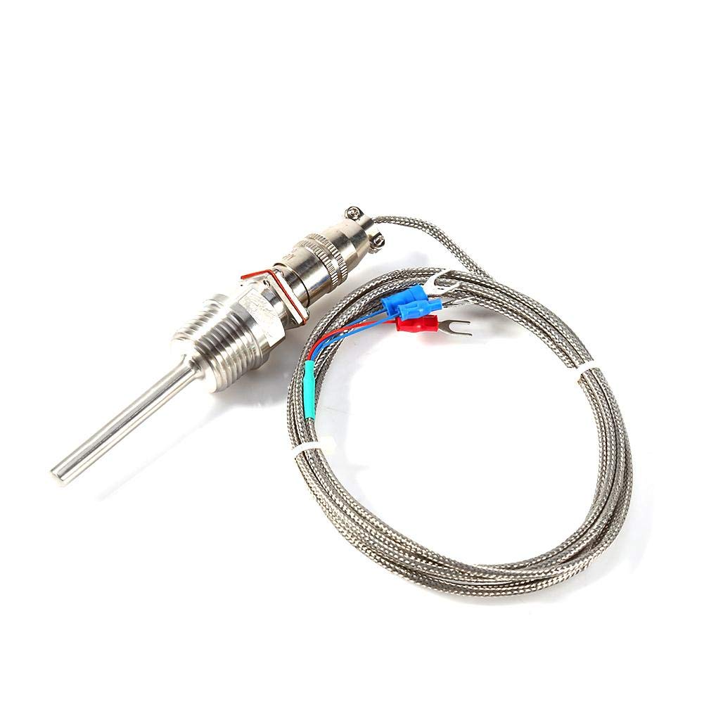
  1. snip off red, blue and blue connectors
  2. solder newly snipped wires to female XLR connector (see question below)
  3. solder 3 wires onto a male receptical that leads to the PID
re step #2 - I understand that the wires have to match their "counterpart" (red <-> red, blueA<->blueA, blueB <-> blueB) and the order matters on the pid...but does the order matter in respect to which of the 3 prongs on either side of the connector I solder? Can I just assume red will be 1, blueA will be 2, and blueB will be 3 on both parts of the XLR connections?
51ukSr3YQ-L._SL1001_.jpg
 
The two blues are interchangeable, so no need to worry about Blue 1 and Blue 2. Just need to keep the the Red separate from the Blues. As far as which color goes to which pin, you can do whatever you want, but settling on a convention like "the odd color always goes to Pin 1" is probably good practice.

Brew on :mug:
 
If one of the three wires is ground or shield or common, (most likely red) best practice would be to put that on Pin #1. Why? If some time down the road you wanted to extend the cable with a microphone or some balanced audio cable, it would almost certainly have it's shield on Pin #1.

As I said, this is just a best practice thing. If have already soldered it together differently, and it works, do not go back and "fix" it.

Couple things to remember about XLRs. When soldering them, they are mirror image. I.e. Pins 1 &2 are reversed (mirrored) for male to female when looking at the back of the connector.

XLRs break the soldering rule of "Do not use solder as glue. Make a good mechanical connection between conductors first."

Tin the wire.
Fill (or butter) the sold Cup first.
Introduce the wire to the solder cup
Heat up the cup and complete the connection.
A three wire RTD does not have a ground or shield wire. The odd colored wire is connected to one end of a precision resistor (the temp sensing element), and the other two wires are connected to the opposite end of the precision resistor. Having two wires connected to the same resistor terminal allows the controller electronics to compensate for the resistance of the lead wires, so that the temp readings (actually resistance measurements) are more accurate.

Brew on :mug:
 
Interesting.

I expect my advice of using Pin #1 for the odd conductor is still valid, but for a slightly different reason. You want the blue conductors to be as close to equal as possible. In a shielded microphone or balanced audio cable, that would be the high and low conductors. The shield being the unequal of three would best used on the single pathed end of the resistor.

Granted, if you remove my variable of using an extension cable, my advice becomes moot.
If you use an extension cable with an RTD, you want all three wires to be the same (material, gauge, length, etc.) The lead resistance compensation done by the controller assumes that all three leads have exactly the same resistance.

Brew on :mug:
 
More interesting stuff. If the PID assumes all 3 conductors to be uniform, then it would be better to avoid using a microphone or balanced shielded cable as an extension cord.

A mic cable or balanced audio extension cable will be a twisted pair with an overall shield. The twisted pair conductors will match, but the shield will have a different DC resistance, different impedance and different LC properties.

I have no idea how forgiving a PID would be with the differences in conductors. So the best practice to avoid twisted pair shielded cables.
 
In my experience, as long as all the connections are soldered (other than the actual plug connection point) Ive had precision that was well within my expectations for brewing. I recommend NOT using the super cheap stainless braided probe wires personally as ifve learned the hard way they are ridiculously fragile and cheaply made with the amound of actual copper wire used being so little that they reinforce it with what looks like fiberglass wrapped with the conductors and the stainless braid which kinks easily damaging these hair like conductors. I use the telfon or teflon sheilded wires myself and have never had one fail yet, even at my brewpub with weekly use.
 
I'm trying to solder one of there. What is a solder cup? a special wire end?

1642637709007.png


The solder cups will be on the XLR connector wire terminals.

Edit: Had the above pic in my original post, and it disappeared. :mad: I put it back, and hope it hangs around this time.

Brew on :mug:
 
Last edited:
Solder cup is where you put the wire onto the connector. It is called a solder cup because it is shaped like cup that has been cut in half.

Put the stripped part of the conductor into the solder cup, add heat to the cup and the wire, introduce solder and fill up the cup.

Unlike most solder joints, here you use the solder as "glue" to hold the conductor to the connector terminal.
 

Latest posts

Back
Top