- Joined
- Mar 15, 2010
- Messages
- 17,572
- Reaction score
- 2,614
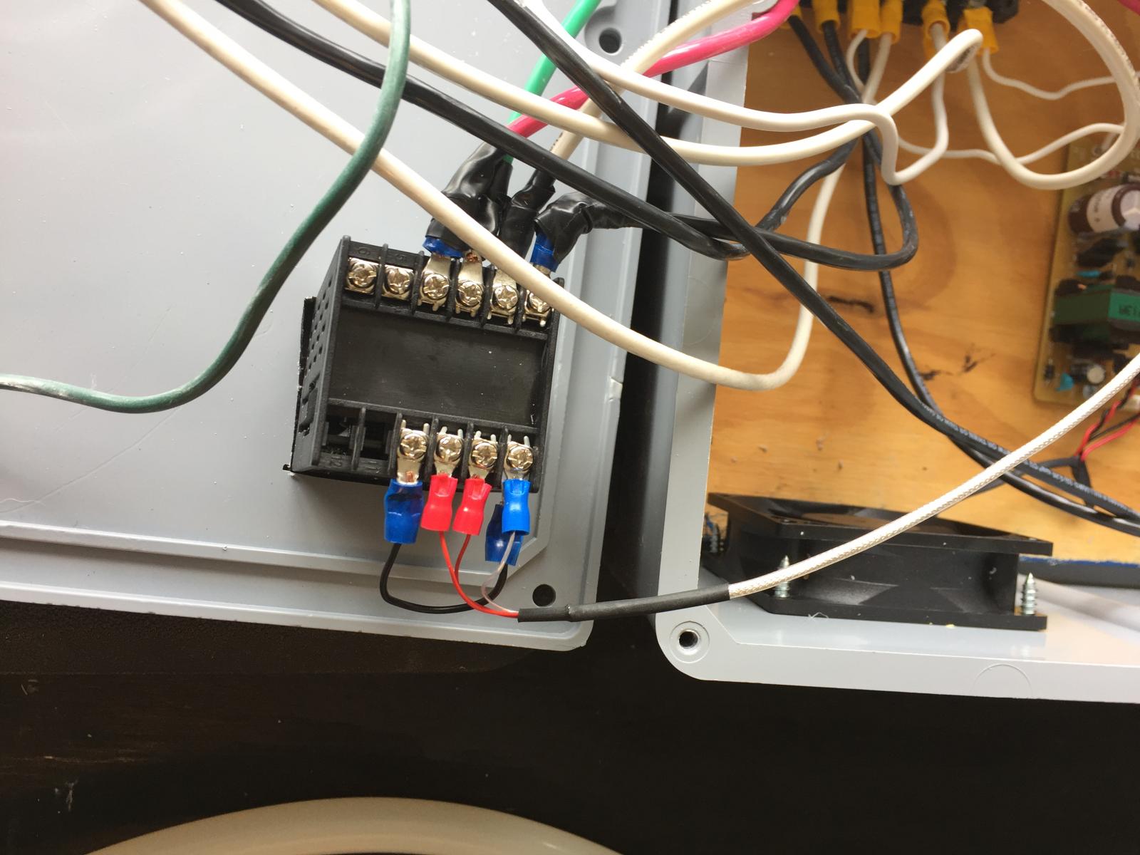
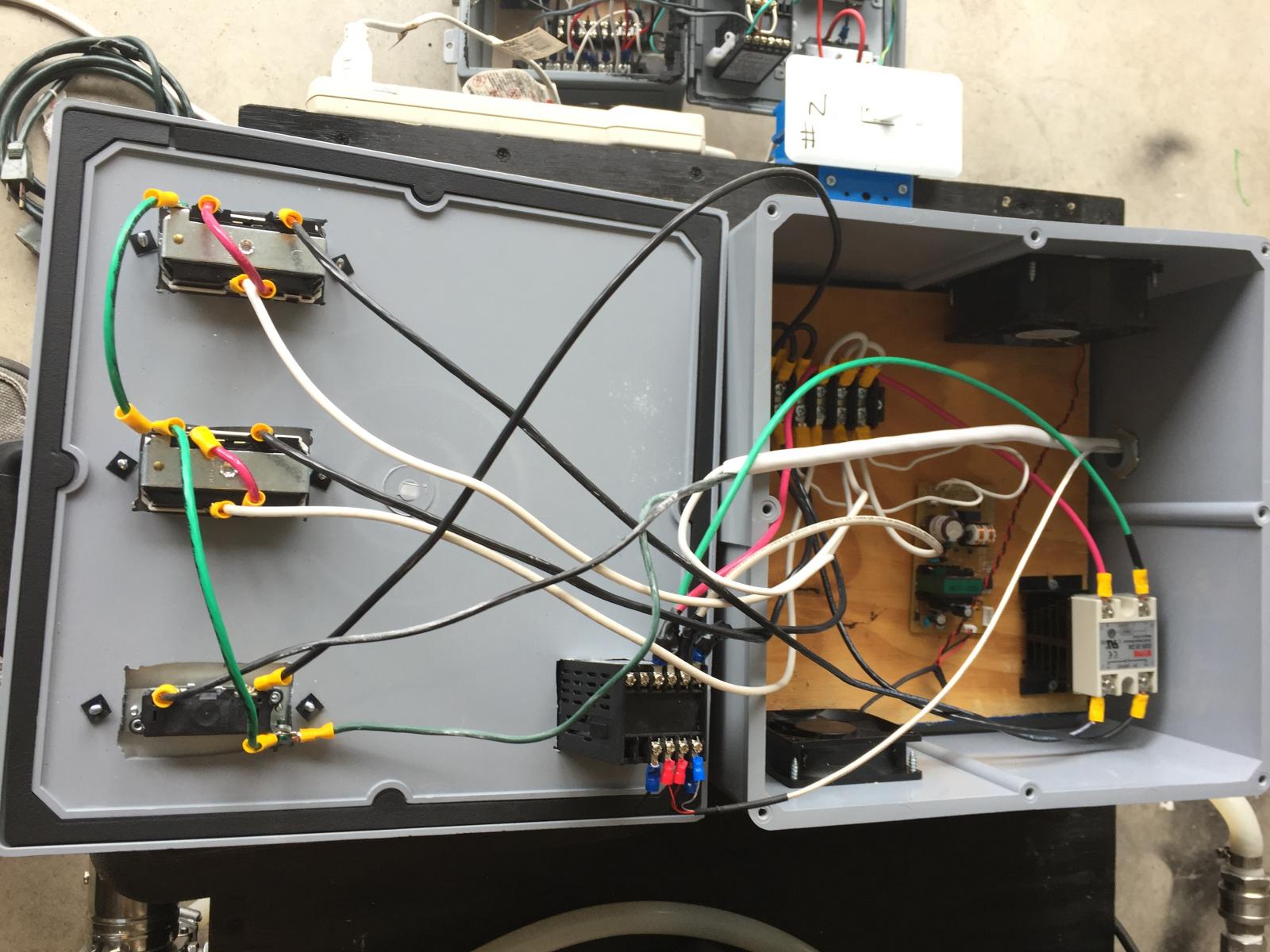
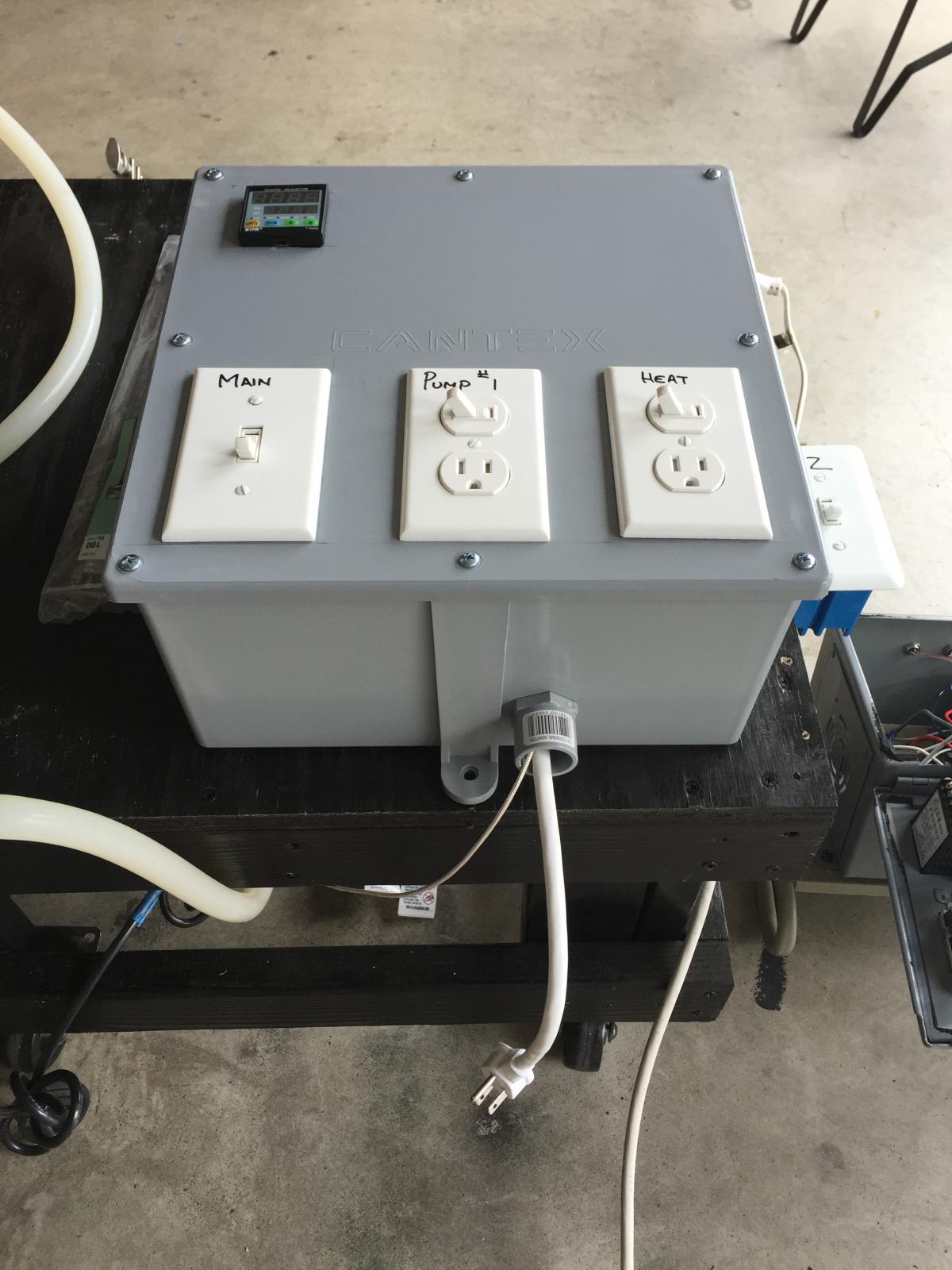
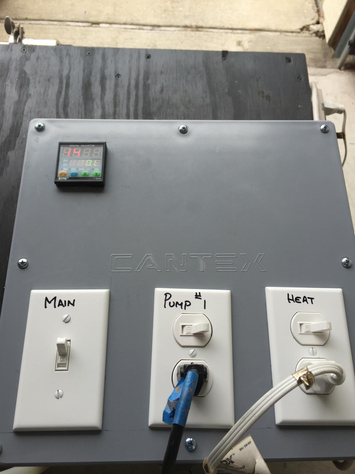
This thread will be exactly what is says, RIMS tube and PID controller FOR IDIOTS. I am no expert when it comes to electricity. I'm not even a novice. I am an idiot. Electricity is dangerous and handle at your own risk. I will have help (more on that below).
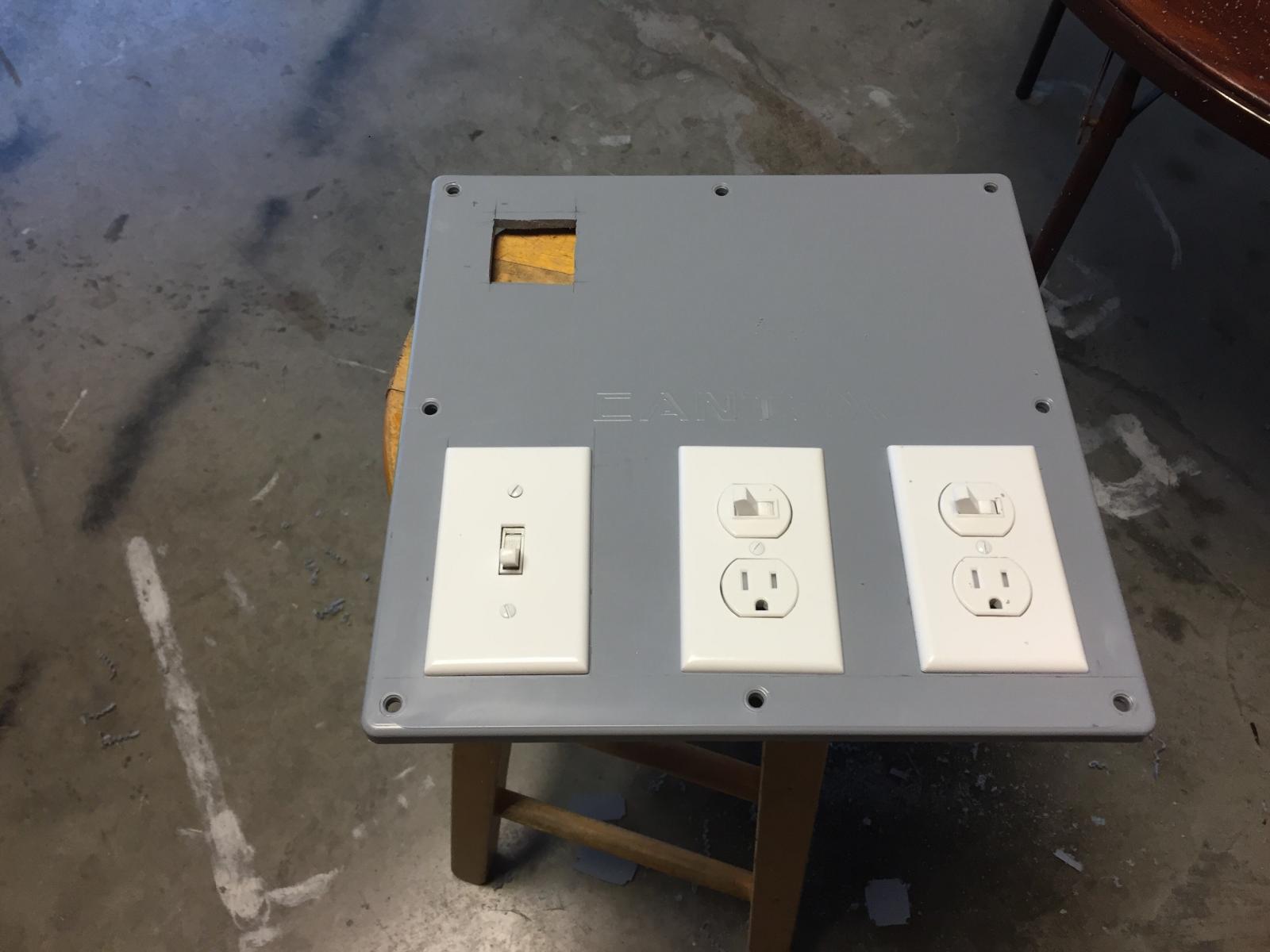
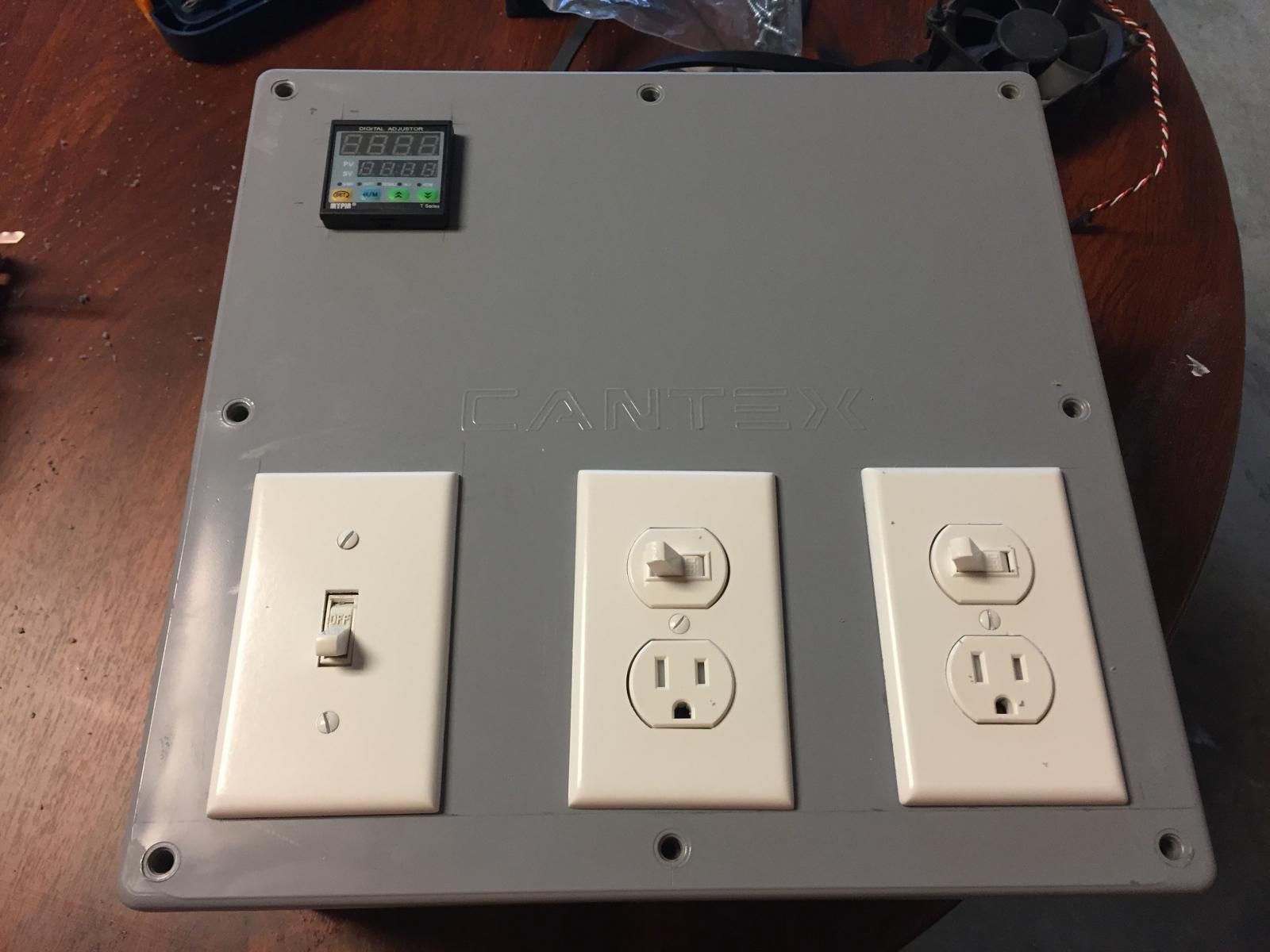
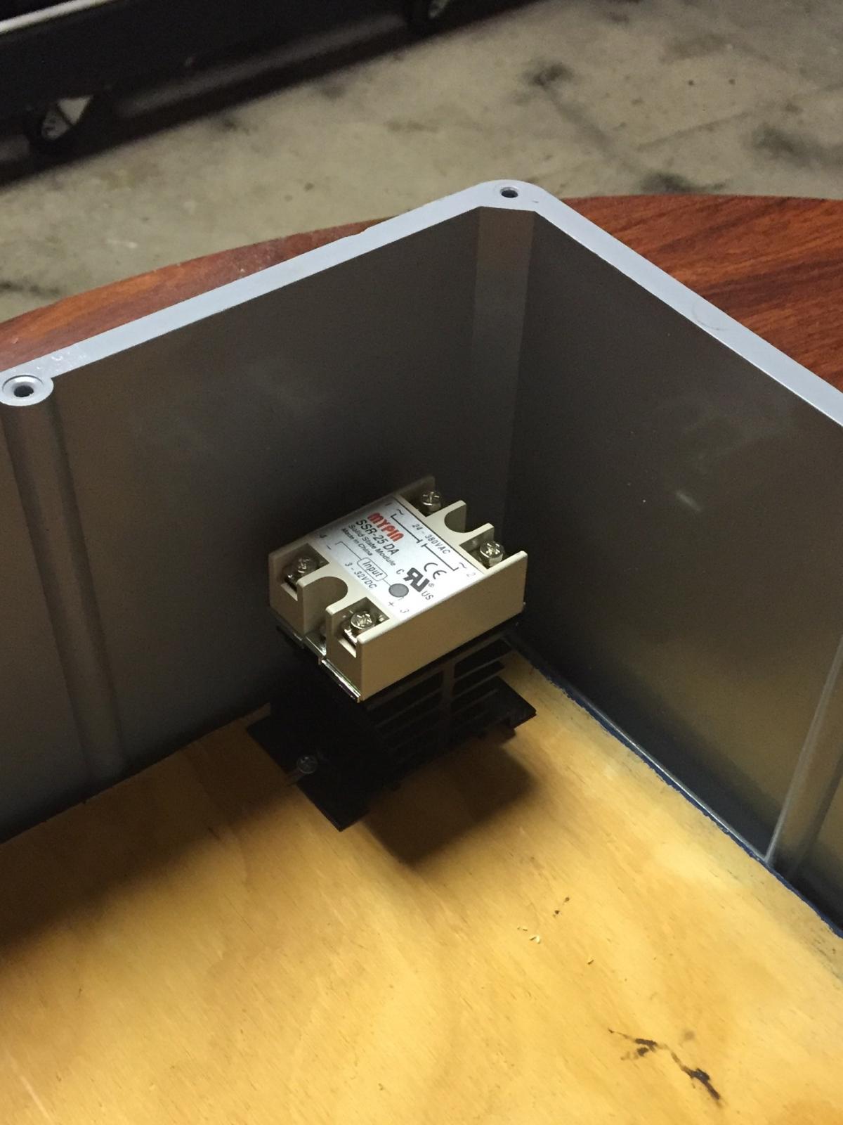
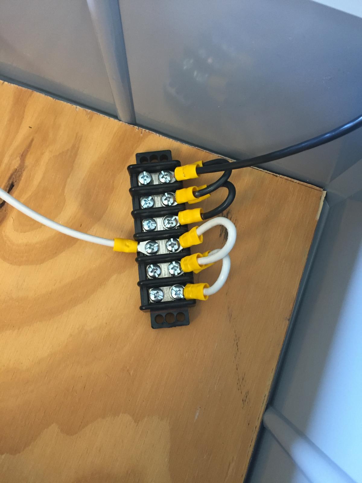
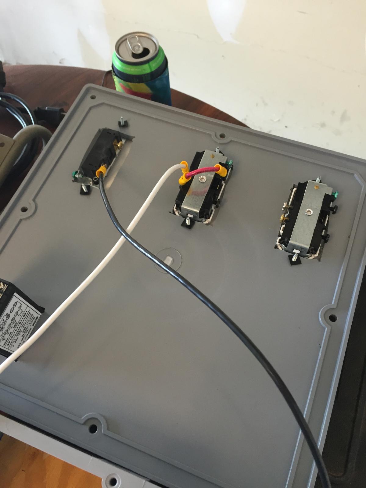
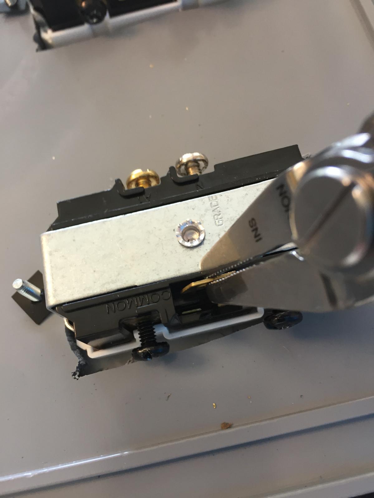
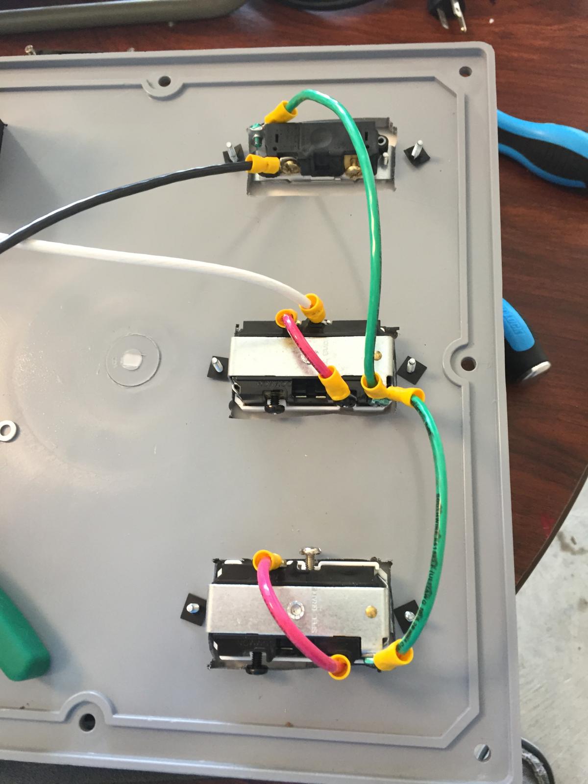
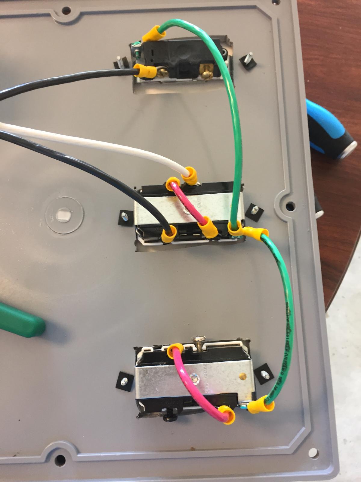
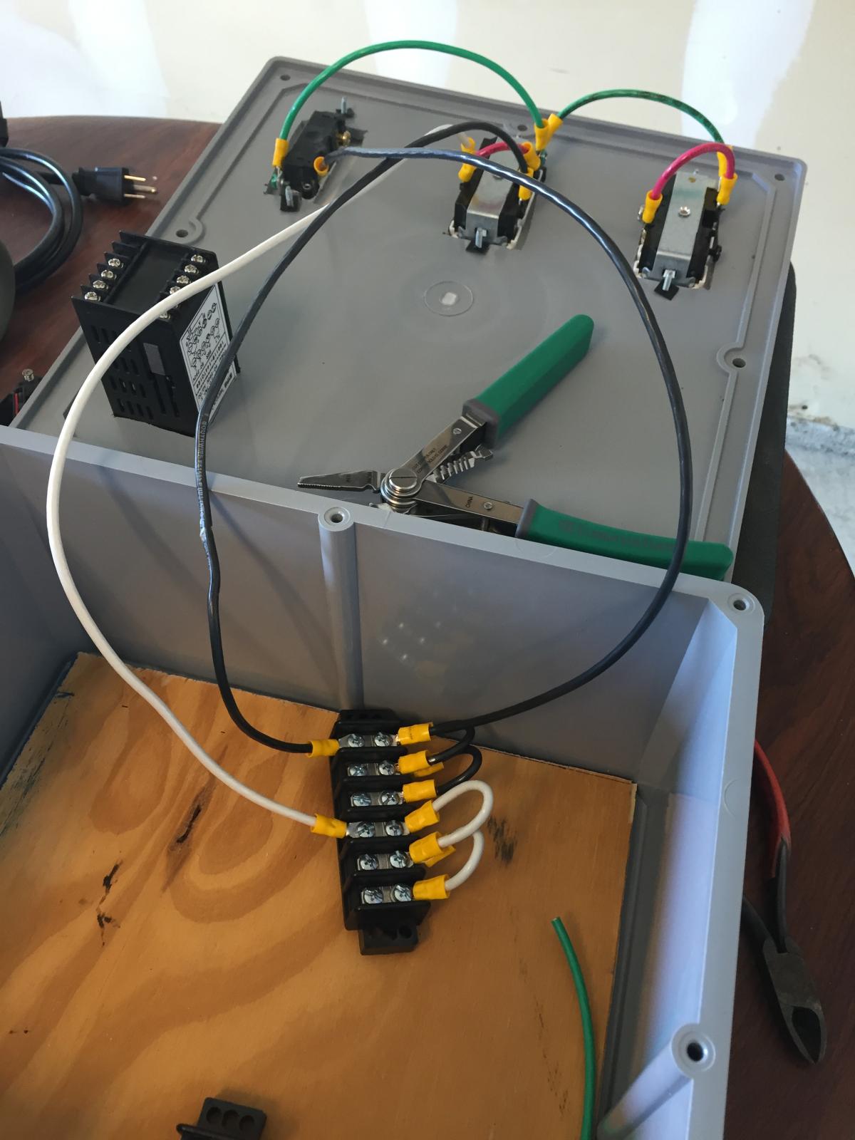
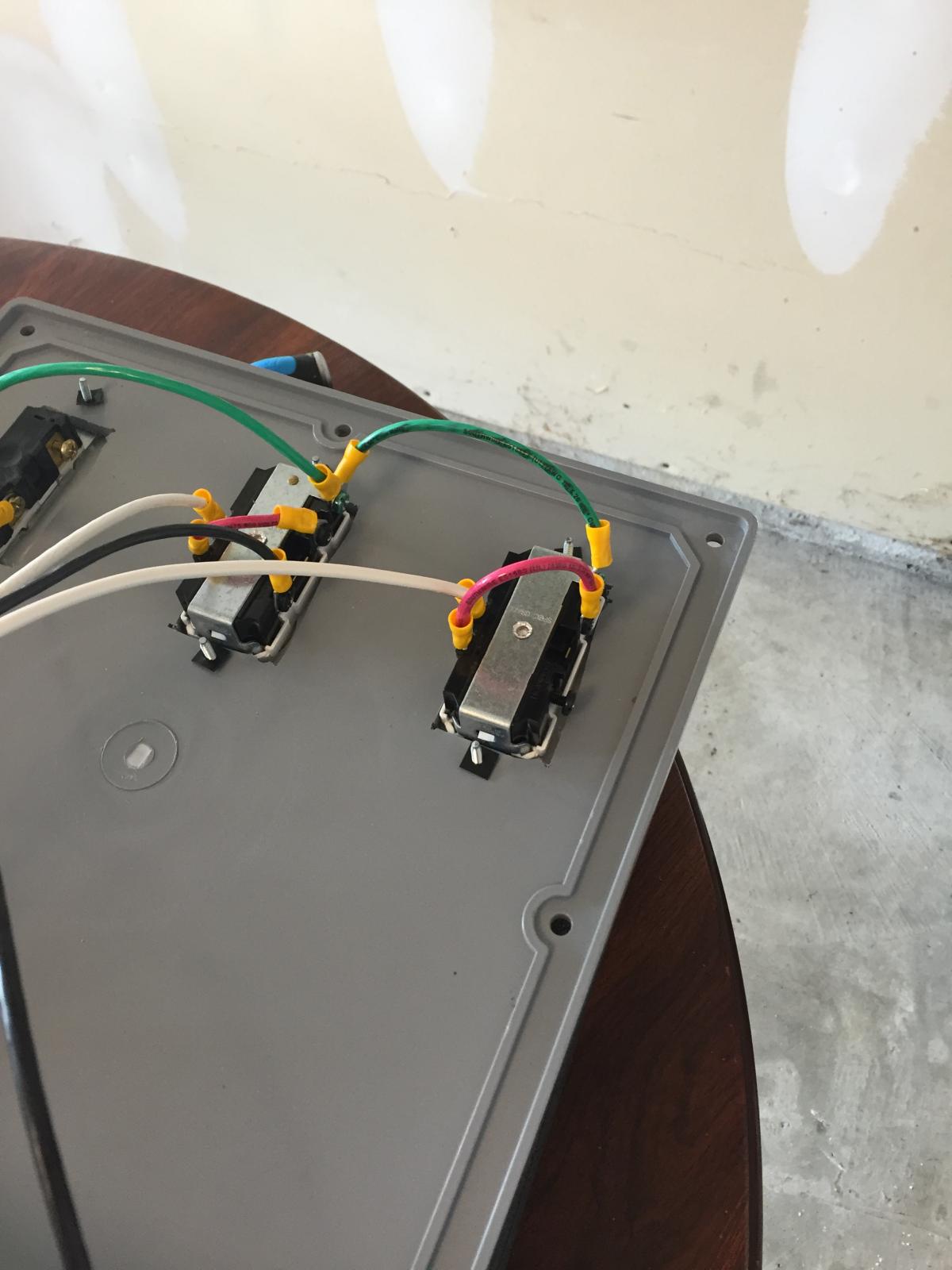
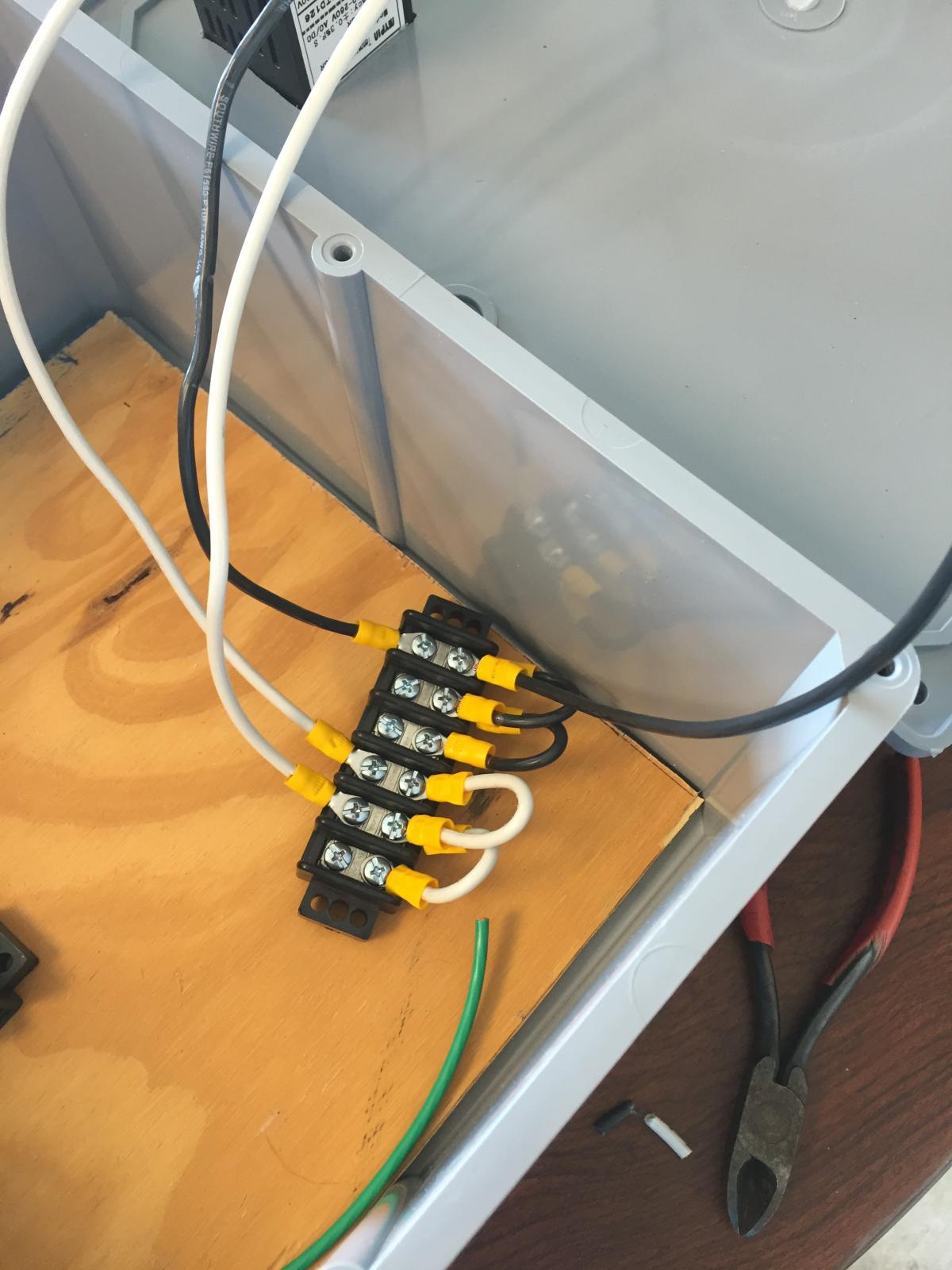
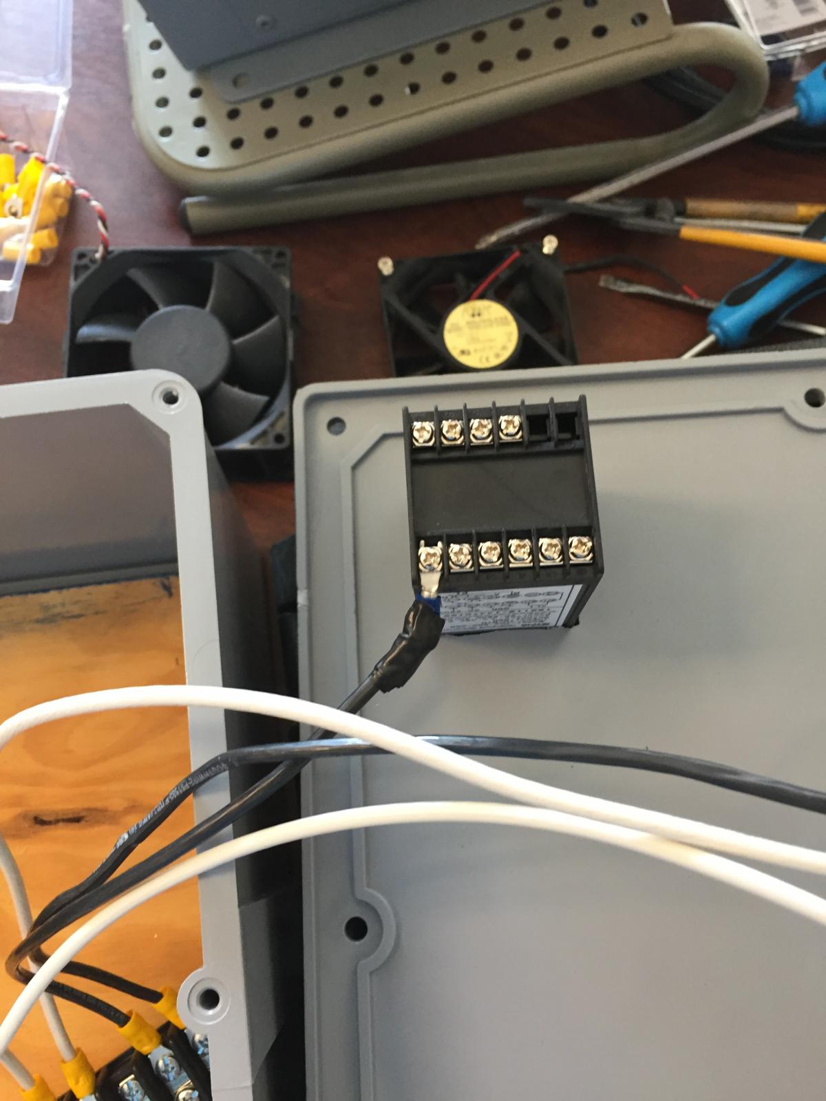
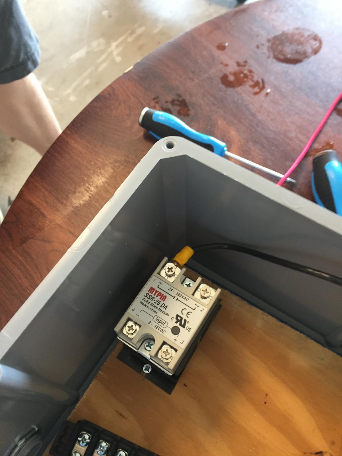
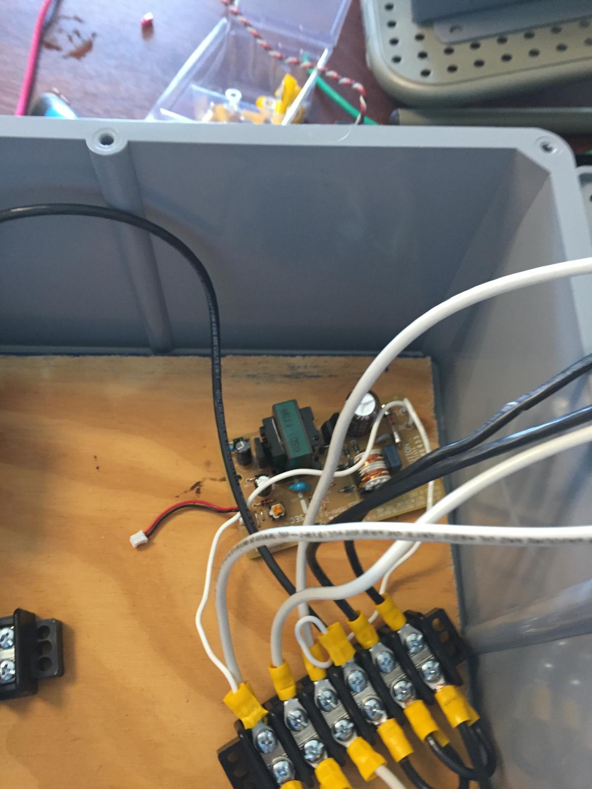
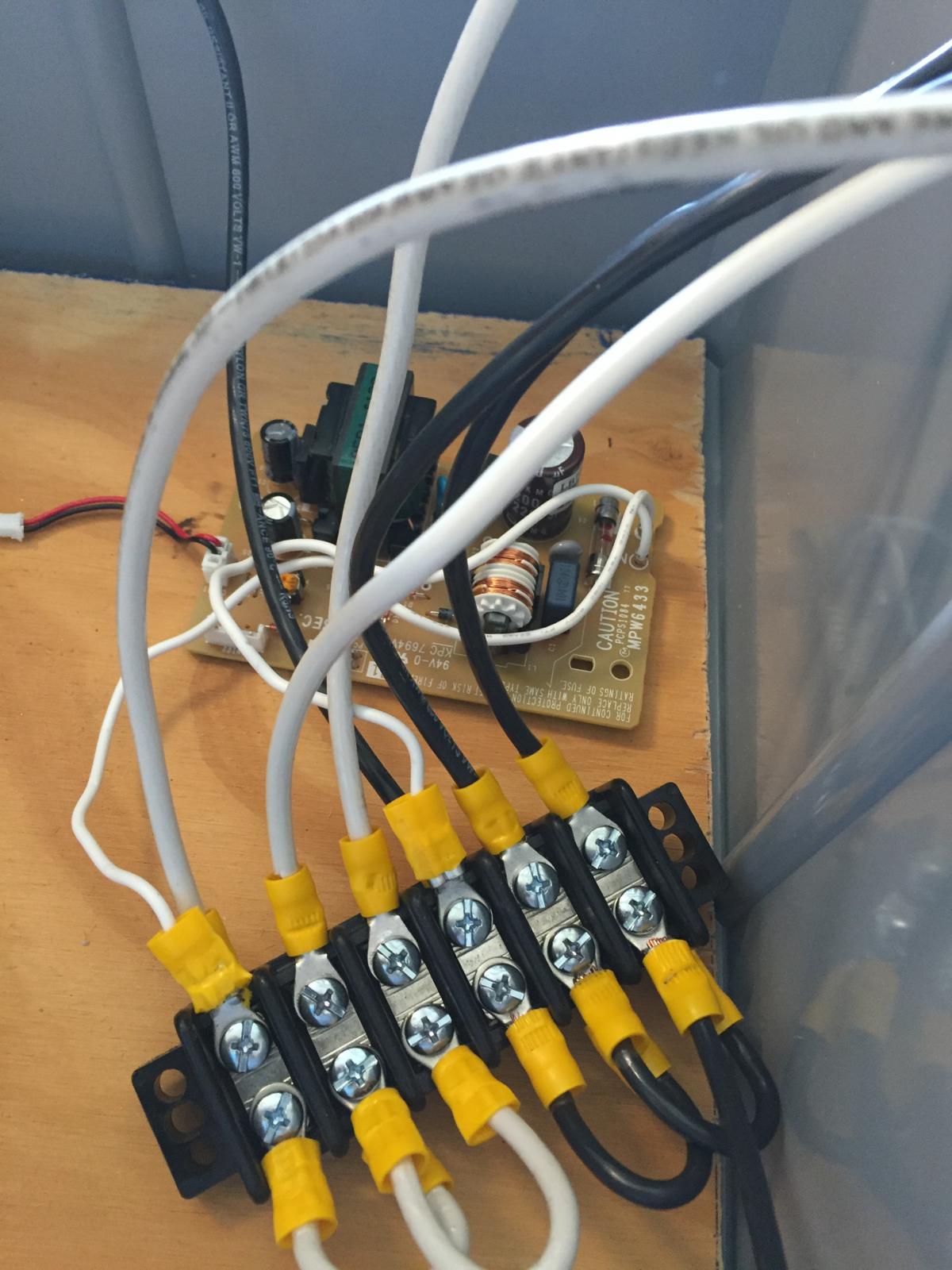
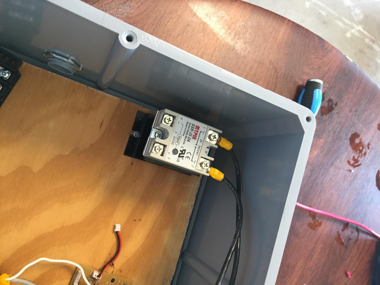
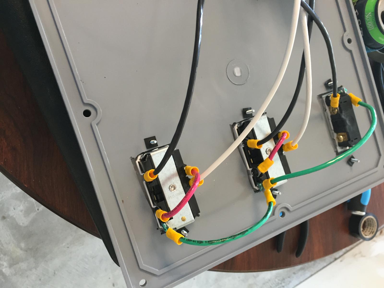
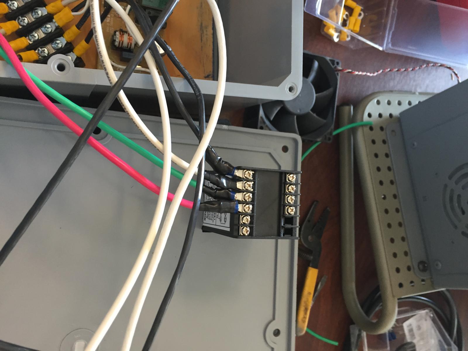
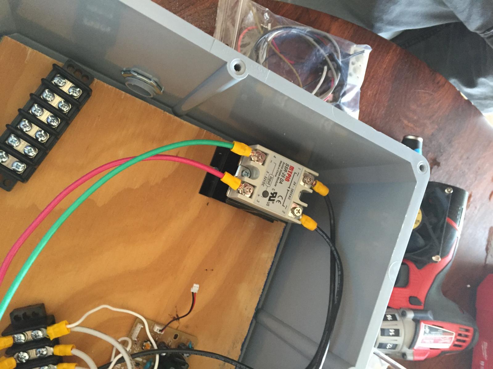
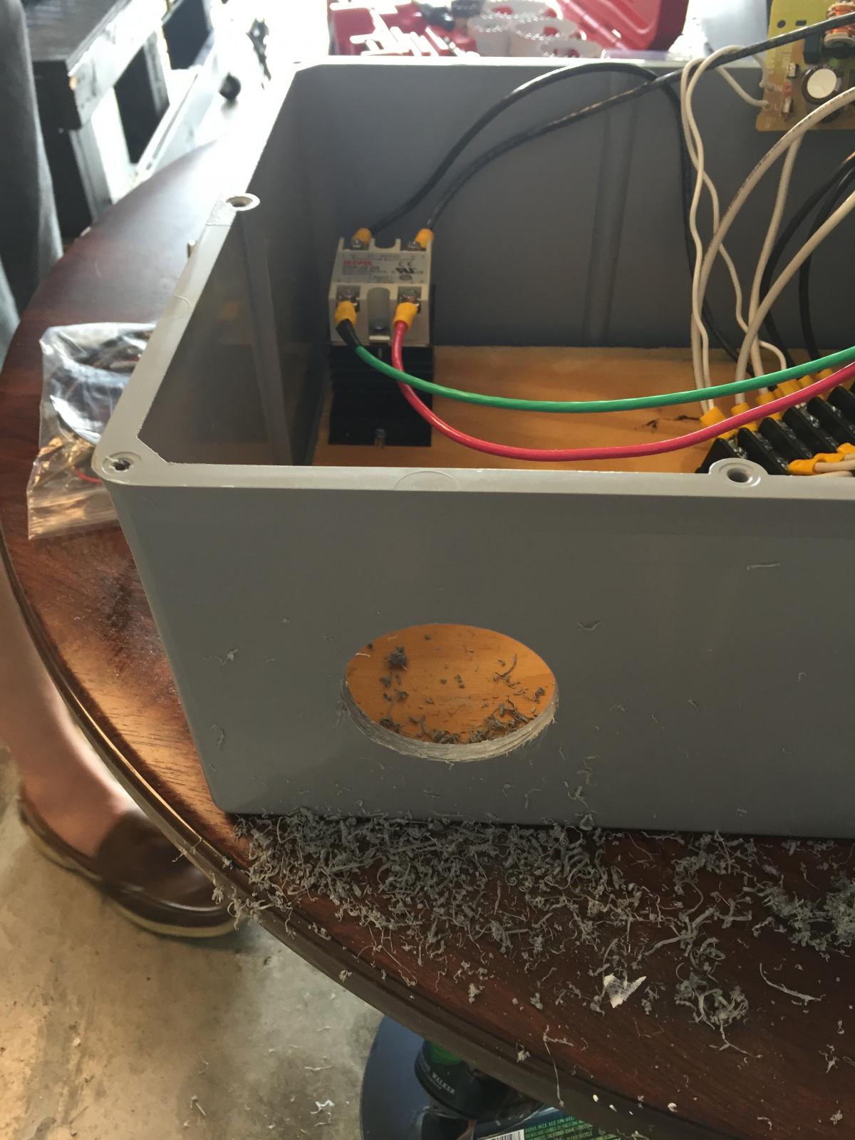
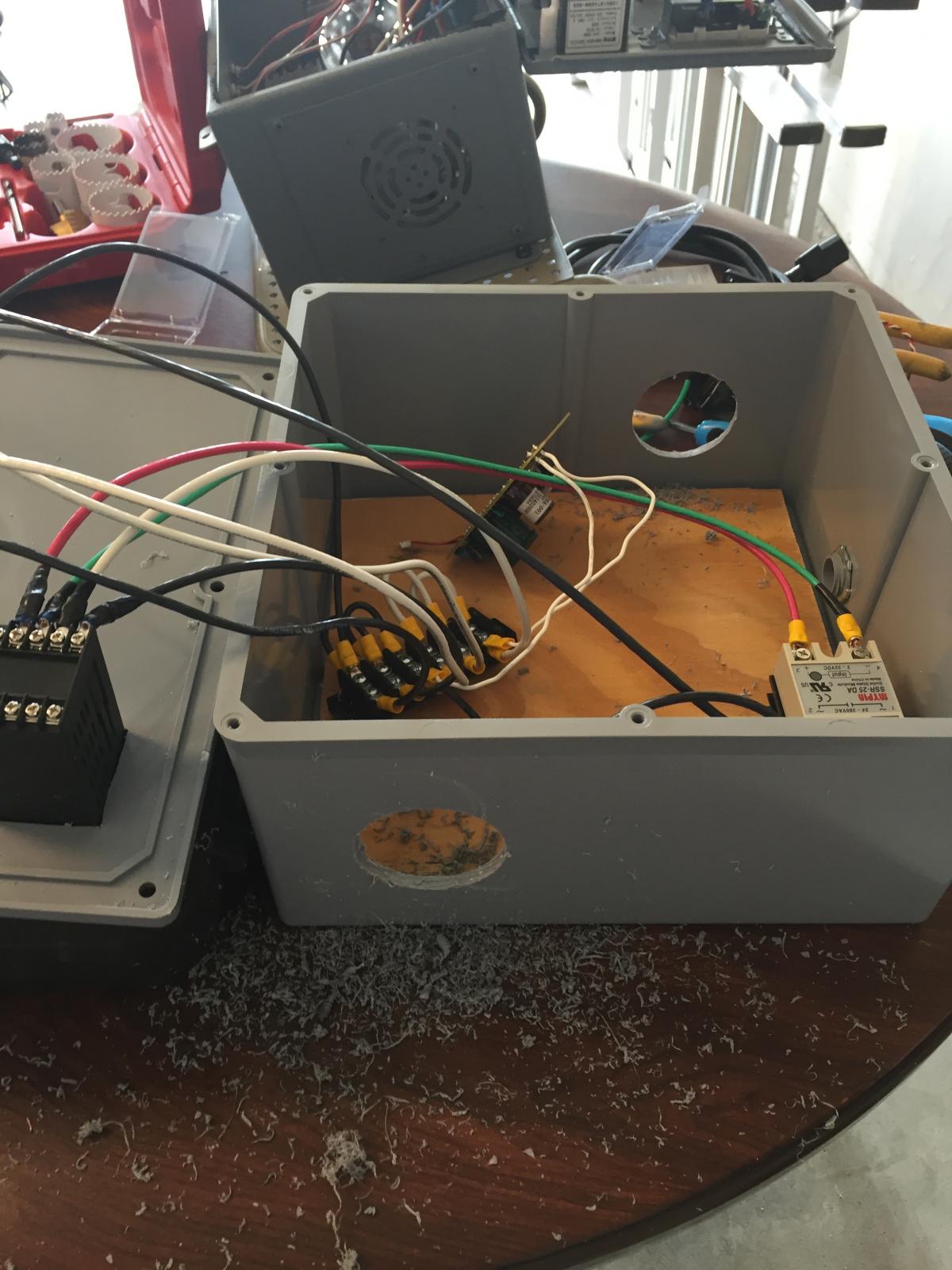
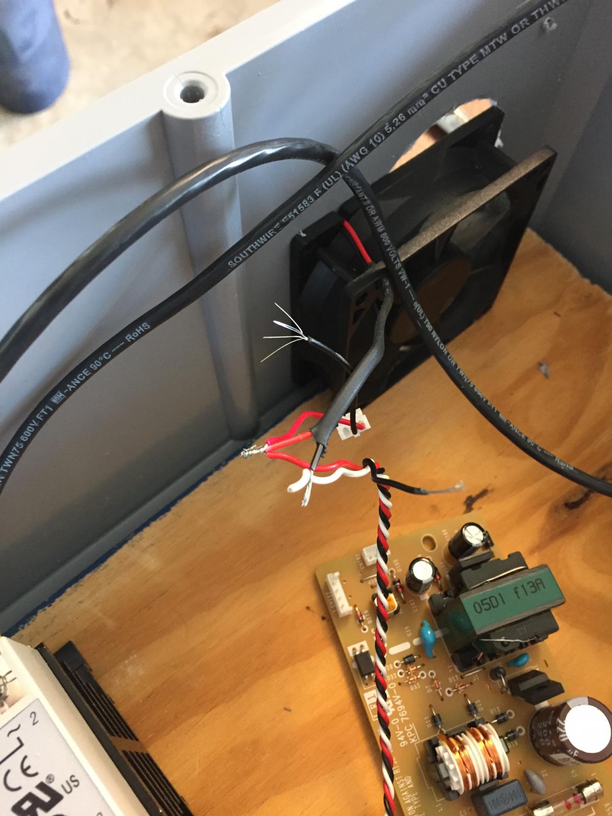
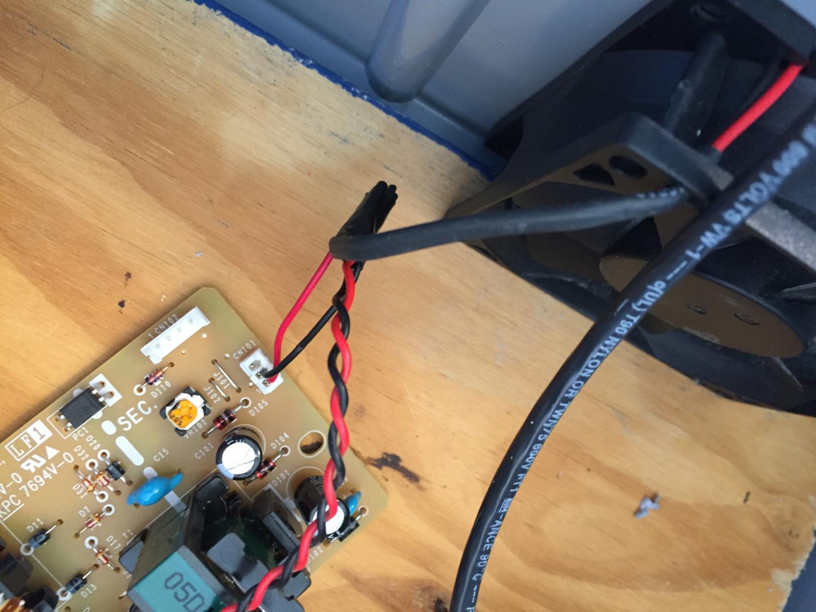
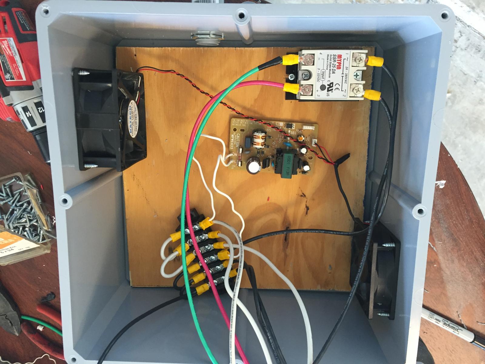
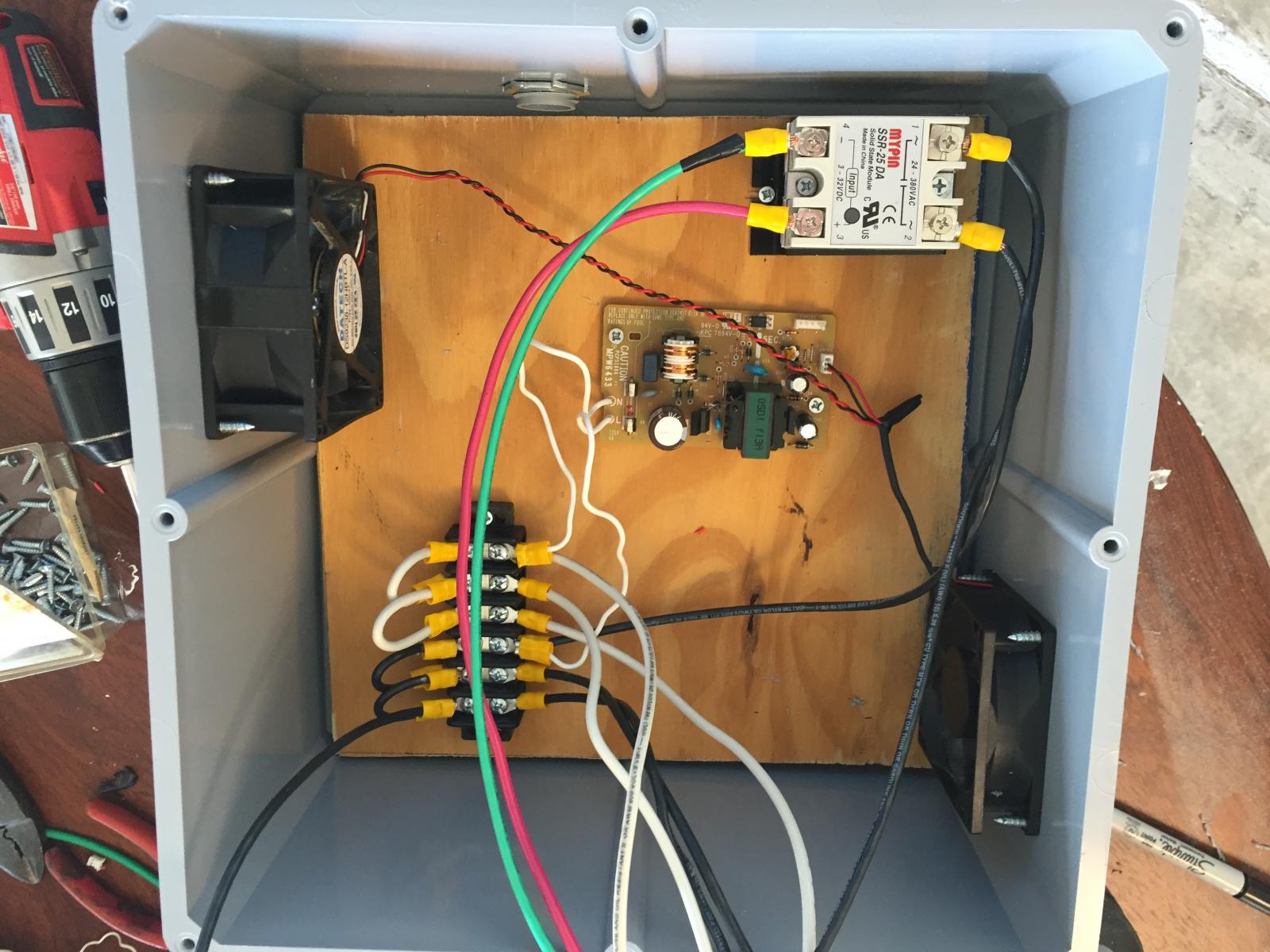
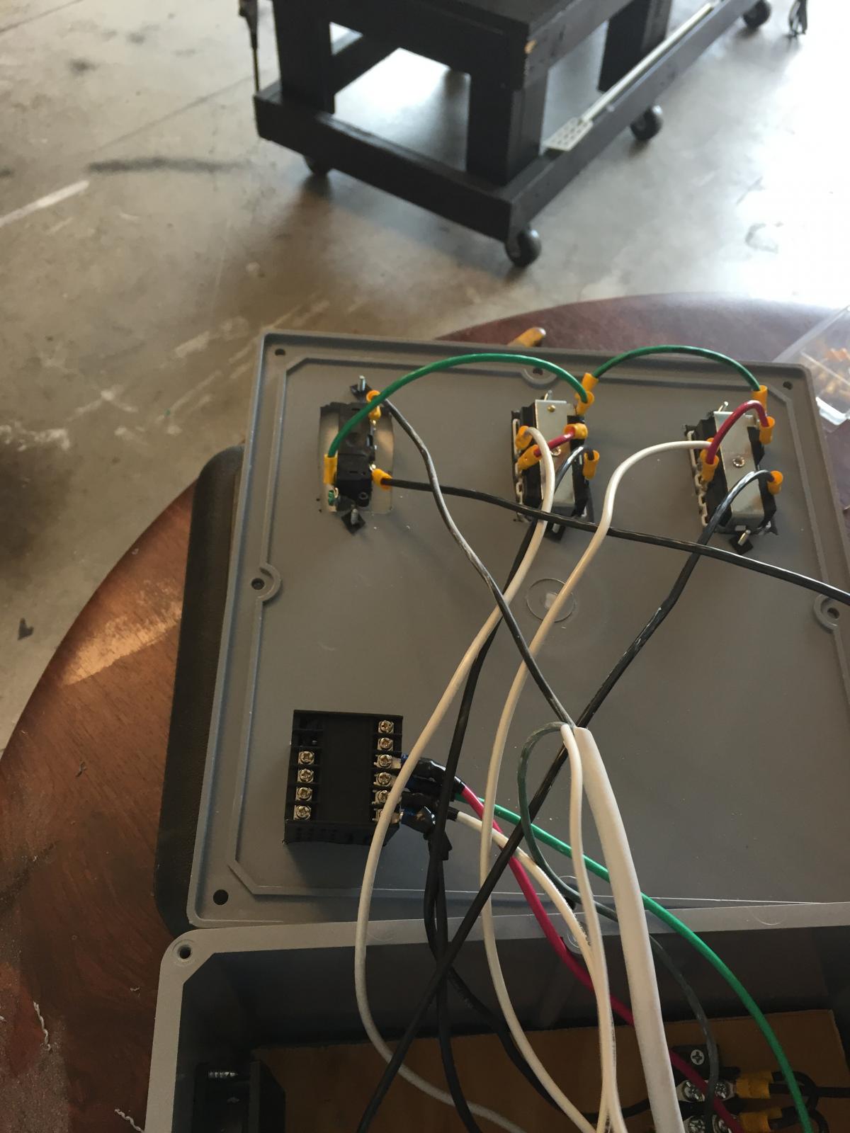
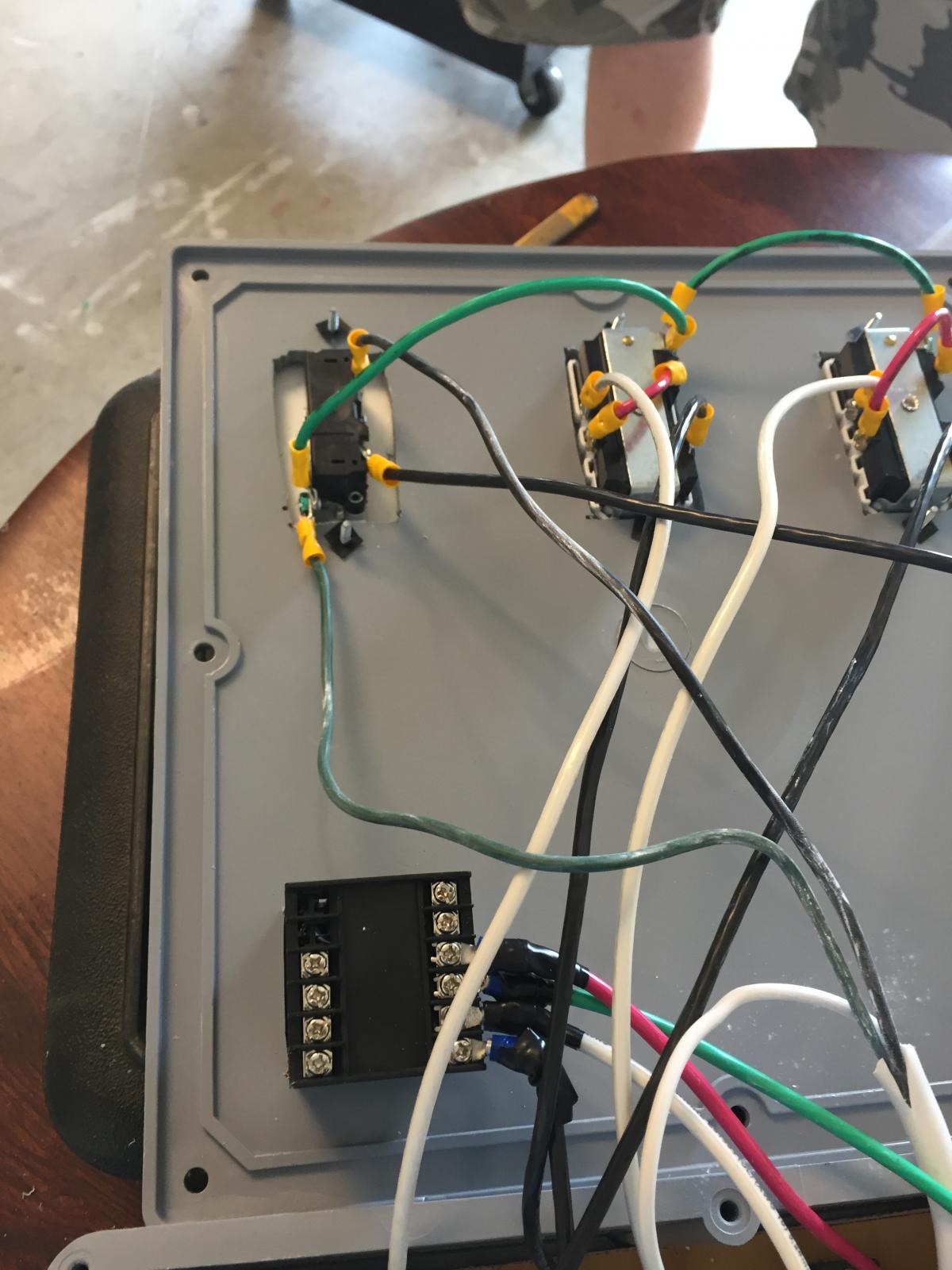
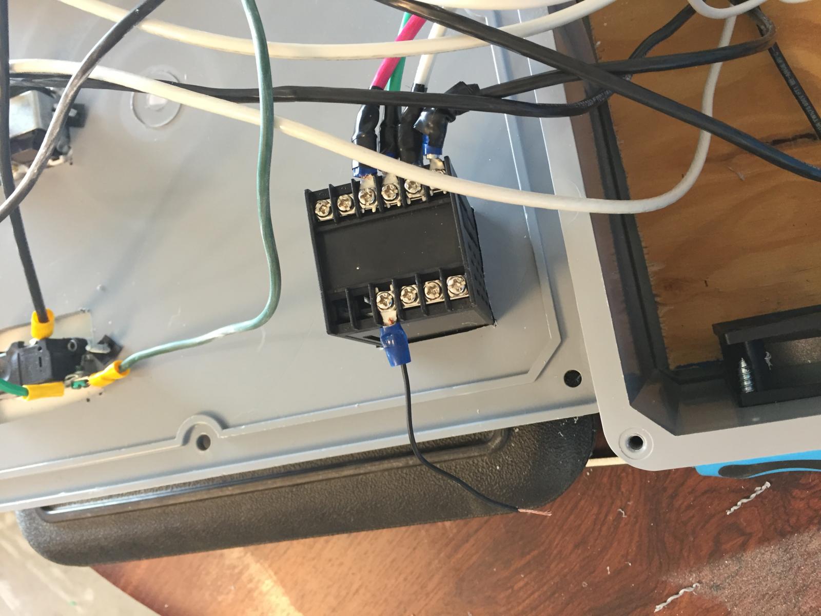
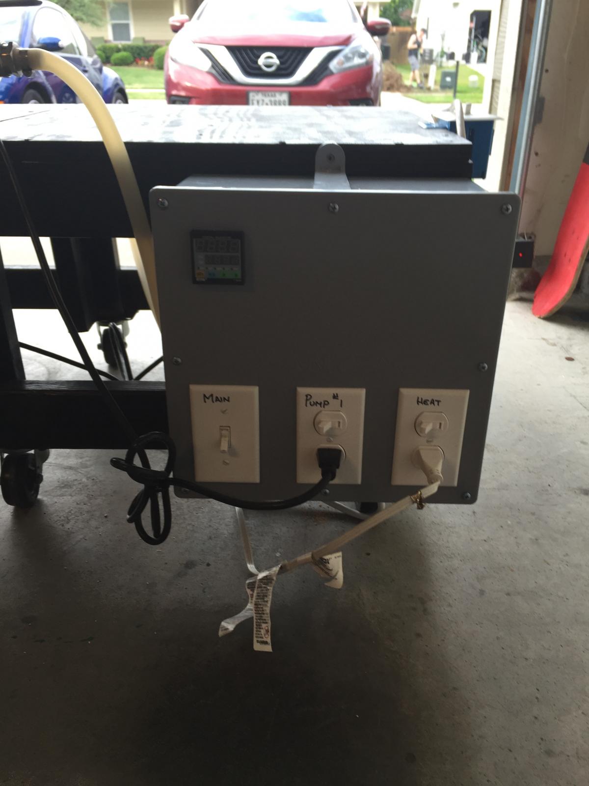
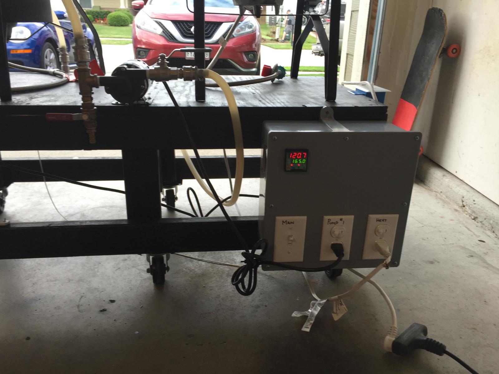
For some time now, I have wanted to upgrade my HERMS coil and propane, to an electric element and a RIMS tube. Over the course of the last few weeks, I have read numerous articles and watched countless videos, on how to assemble a PID controller and RIMS tube. With the help of a friend (who recently built one and understands this stuff), I assembled a list of parts and started ordering stuff. As my parts started coming in, I realized I had no idea what to do with any of it. No matter how many articles I read or videos I watched, I could not wrap my head around what was going on. So I decided that I would start a "for dummies" thread. Over the next few days (I hope), I will be documenting, step-by-step, how I built my controller, with pictures and possibly some video.
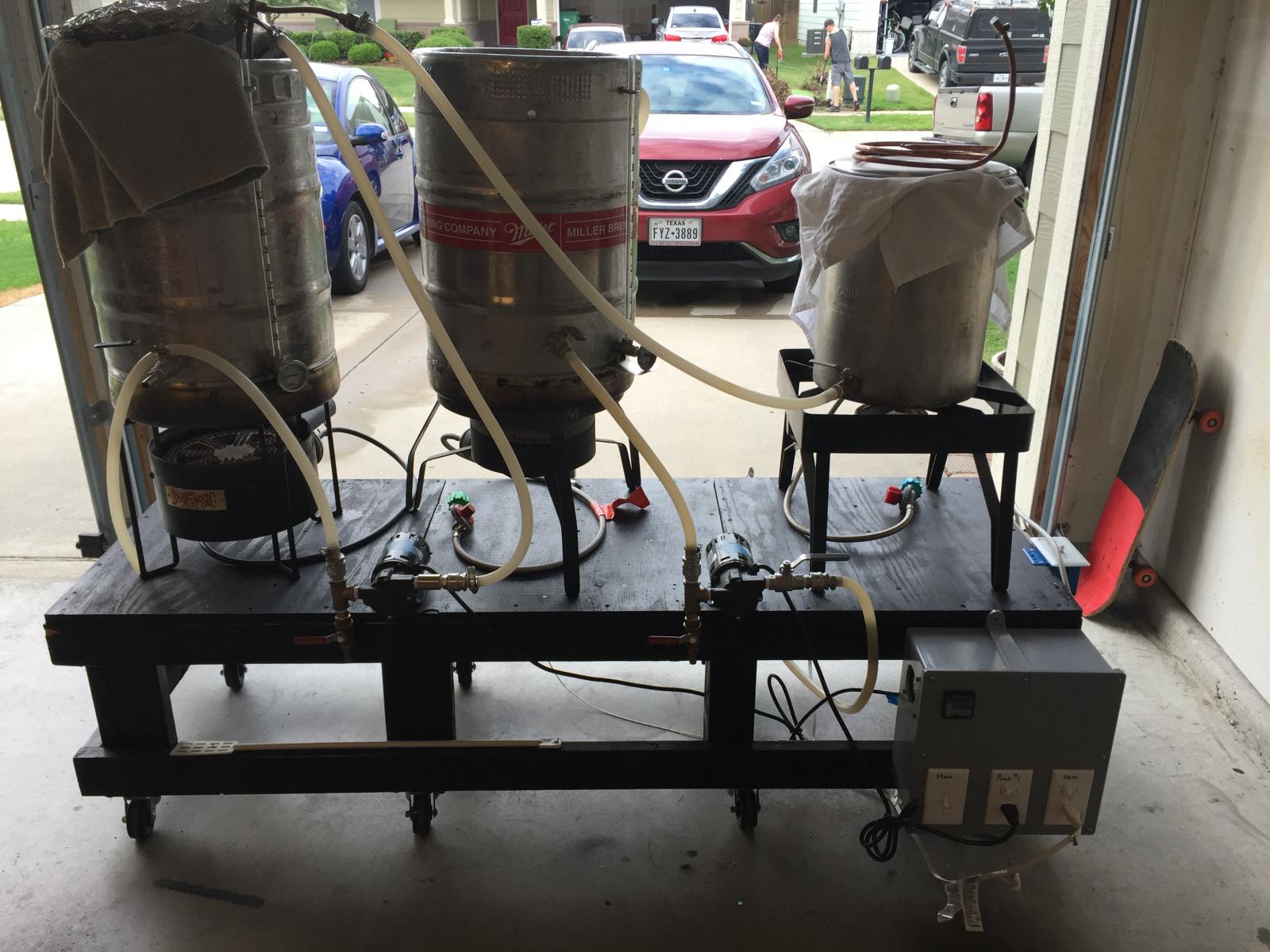
Let's start with my current set-up. I have a 3 vessel system, 2 keggles (MLT & BK) (left and middle) and an 8 gal aluminum pot for an HLT (right). My system has 2 pumps, one for recirculating the mash through the HERMS coil (submerged in the HLT) and one that I use mostly for chilling. For chilling, I fill the HLT with water and pump it through an immersion chiller in my BK. As the water heats up, I add ice. I can usually chill from boiling to 68F in about 30 minutes using 3 bags of ice. My intent is to replace the HERMS coil and propane burner with a RIMS tube and heating element. I will still use the HLT as my chill water. Here is a picture of my current system. 1st pic
Here is the parts list of what I ordered for the upgrade:
http://www.amazon.com/dp/B0087O6S2A/?tag=skimlinks_replacement-20
http://www.amazon.com/dp/B00FHVBKC4/?tag=skimlinks_replacement-20
https://www.brewhardware.com/product_p/rims18_cam.htm Make sure you order the connections that fit your system. If you use, QD's you need to specify which ones, and make sure that you have enough of each. I sat down and wrote out the path of the wort from the MLT and back to ensure that I ordered enough of the parts I needed.Last pic
https://www.brewhardware.com/product_p/element5500.htm
You will need a ball valve on the out side of your pump to control the flow of wort. I ordered another one from Brew Hardware as well. See the "Path" list below for my exact configuration, keeping in mind that I used some of the parts I already had so I didn't have to order new everything. Also keep in mind that you will need some misc items like wire, connectors, wire nuts, etc...I picked this stuff up at Home Depot.
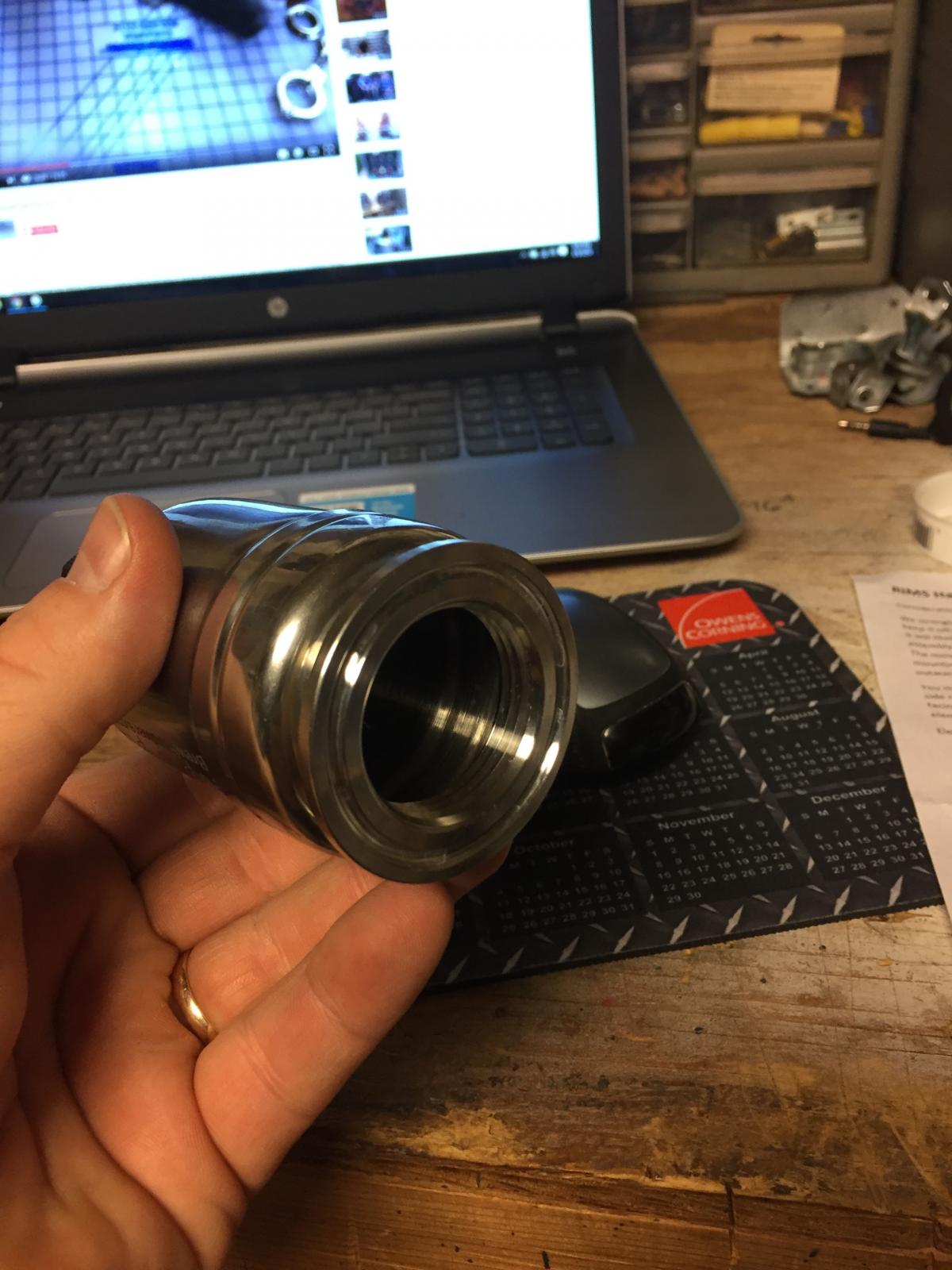
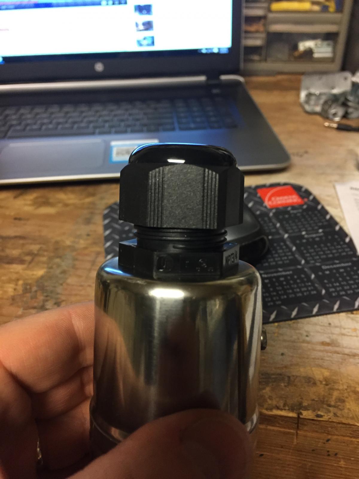
So the first thing I did was start playing with the RIMS tube. Kudos again to BobbyM @ Brew Hardware. I'm never disappointed in anything I buy from them. Never having seen a RIMS tube before I wasn't sure how to install the temp probe or heating element. After much frustration (and then finding a video of BobbyM showing how) I figured out which parts come apart. 2nd and 3rd pic show how/where the element end comes apart.
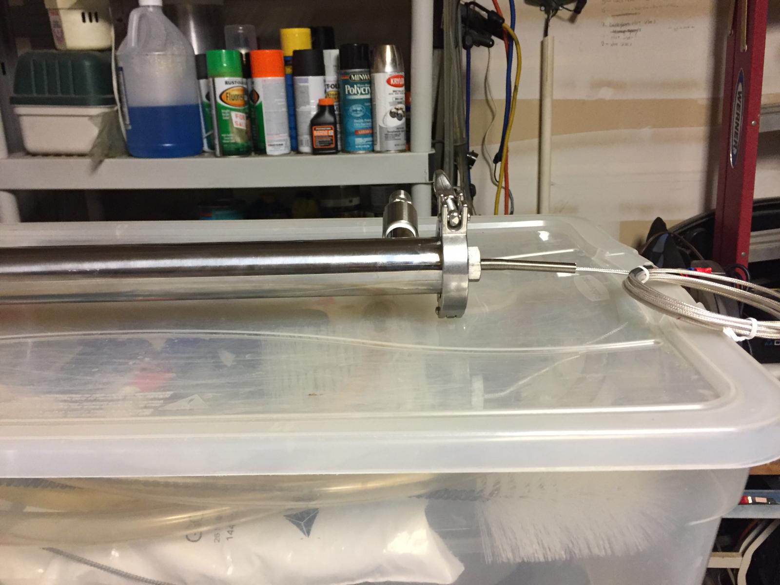
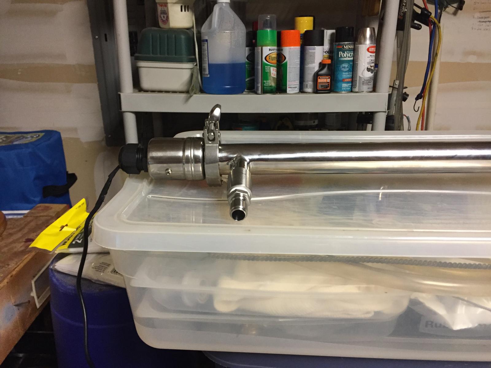
And here is the final assembled tube. 4th pic
I hope you're having fun with this. More to come soon...
Edit: I'm not sure how to type above or below a pic so until I figure it out, listing them by number will have to work. Maybe I'll do the rest with individual pics and posts.


Last edited by a moderator:


