Rasberry pi help

Homebrew Talk - Beer, Wine, Mead, & Cider Brewing Discussion Forum

Help Support Homebrew Talk - Beer, Wine, Mead, & Cider Brewing Discussion Forum:

This site may earn a commission from merchant affiliate links, including eBay, Amazon, and others.

DevildogJn

Active Member
Joined
May 10, 2014
Messages
32
Reaction score
3
Location
Belgrade
IM building a 3bbl electric brewery and came across this wiring diagram from P-J to handle 4 elements. This is showing a pid but I want to have an automated system running raspberry pi and the strange brew elisnore created by Doug Edey. Can anyone be so kind as to look at this and tell me how it would wire to the rpi instead of the PID and if it would be compatible to run 4 elements in a single vessel with Elisnore. Thank you.
http://www.pjmuth.org/beerstuff/images/Auberin-wiring1-a11b5-RM-SYL-2352-5500w.jpg
this is the link to the thread with the wiring diagram.
 
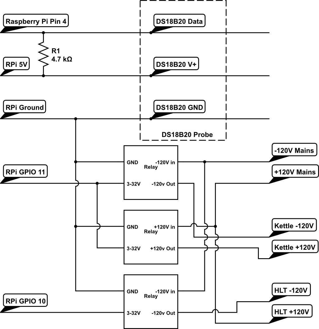
You basically need this drawing from the initial Strangebrew post

rpi_circuit.png


Just know where it says Raspberry Pi Pin 4 it actually means GPIO4 which is pin 7. You would wire your probes to RPI as shown in the top and then take any other GPIO thats available such as GPIO11 and wire it to your SSR's.

I dont see why it wouldnt work? Although im not sure if the RPI's pin has enough juice to power 4 SSR's. You would just chain together all your 3V input's on your SSR's to the GPIO so they would all trigger at once. Worst case i think you could create 4 seperate Elsinore devices each controlling a seperate GPIO to turn them on and off individually? I think that may give you better control anyways as once you boil you could turn 2 of them off for example just to maintain the boil.

Doug or another Strangebrew guru will have to chime in on that.
 
16ma per active GPIO, not to exceed 50ma total.

SSR's typically draw less that 15ma on the input.

I guess the question is how much less..if its 10ma he can pull all 4 with 1 GPIO pin..if its 15 he cant. I guess the only real way to know is to hook up a multimeter with one on and see if OP needs can put them all on one GPIO or if he needs to split across 2 GPIO pins
 
I guess the question is how much less..if its 10ma he can pull all 4 with 1 GPIO pin..if its 15 he cant. I guess the only real way to know is to hook up a multimeter with one on and see if OP needs can put them all on one GPIO or if he needs to split across 2 GPIO pins

Yup - and I got the 15ma number from the Crydom website - so Chinese SSR current draws could differ - I'd measure them.
 
If a transistor would be a fix, where would it be installed? I'm not an electrician by any stretch of the imagination but I am going to give this info to my electrician to build the panel for me.
 
This is my second disclosure in a row... I'm not an electrician, or electronics engineer, or anything like that. Any of this should get double checked by someone who knows what they're talking about.

That said, this is what I was thinking:
KpzqOG6.png
 
This is my second disclosure in a row... I'm not an electrician, or electronics engineer, or anything like that. Any of this should get double checked by someone who knows what they're talking about.

That said, this is what I was thinking:
KpzqOG6.png

That will work. I personally would use an N-FET instead of a bipolar. If you go that route you don't need the resistor.
 
What resistors? Thanks for all of the help guys. I'm going to order the parts once my list is finalized and start the build in January. I got an investor that is anxious to see me get this going,(and for him to get his money back). If it works the way I think it will I should have my brewery open for business by the end of the summer.
 
Back
Top