Portable 240v Spa panel w/ PID and AMP/ Volt meter

Homebrew Talk - Beer, Wine, Mead, & Cider Brewing Discussion Forum

Help Support Homebrew Talk - Beer, Wine, Mead, & Cider Brewing Discussion Forum:

This site may earn a commission from merchant affiliate links, including eBay, Amazon, and others.

Alteruser_404

New Member
Joined
Jun 16, 2020
Messages
4
Reaction score
0
Hey everyone,

So I am trying to build a 220v portable GFCI controller with the ability to have one 120v for running a pump. I have it almost down on paper but I am confused about a couple of things, and I would also like a sanity check since I second guess myself quite a bit more than I'd like to admit. I have been reading through the forums and watching tons of videos however, I am still a little confused after looking over a few things.

On a video I saw from Barley and Hops Brewing, they were wiring a 220v 3 prong cable to an Inkbird ITC-106VH. in the video he wired one leg of the incoming 220v to one side of the outlet, then the other leg to the SSR pin1 then from pin2 of the SSR to the other side of the receptacle. What is confusing me on this is once the system is turned on wouldn't there be a constant 120v leg sending power to the outlet, therefore running the heating element at 120v unit the SSR kicks in and runs the additional 120v leg to the other pin causing the element to receive a full 240v?


I have a 4 prong dryer outlet that I am going to be using to send power into the 50A GFCI SPA panel, then from the spa panel I am sending the power into the box I am building to house all of the electronics. There is a diagram of how the spa panel is wired, along with the incoming 220V from the 30A 220V dryer plug I am using. Where I am confused is when it comes to connecting the PID controller, SSR, and L6-30R wires. I do want to have one main switch that I will have to turn on even if the breaker is on. The 120v I can wire along pretty fine, the confusion is with the 220v. Do I send L1 from the top load out of the switch when on to the X of the L6-30R, then L2 to the SSR pin 1, then from SSR pin 2 to Y on L6-30R? I know I have to run power directly to the PID Controller so I will have to run a line from the two loads to the PID do I run L1 off the line going to X of the L6-30R to pin 10 on the Inkbird PID and then run L2 from Load on the main on/off switch to pin 9 on the Inkbird PID.

Pictured is also a digital AMP/Voltmeter I would like to have running so I know the load of everything that would be running in the system, 120v pump and fan included. That portion I am not sure of how exactly to wire up. I have posted a link to the unit below, any help would be greatly appreciated. Worst case scenario, I return it.
AC POWER METER.

Thank you for your time.
 

Attachments

  • IMG_20200616_233100.jpg
    IMG_20200616_233100.jpg
    831.1 KB · Views: 37
So digging into youtube a bit further, I found another video from barley and hops showing pretty much the setup I am looking to do, I am still worried about making sure I have the Neutral and Ground properly connected to the GFCI Circuit breaker so any help there would be greatly appreciated.
 
You are correct that when the SSR is off that there will be 120V on the element, however, since almost no current flows thru the "off" SSR, there will be close to zero power going to the element. Power is only delivered when current flows. If you interrupt the current flow anywhere in a loop, then no power is delivered to the loop, even if there is voltage. This is why you only have to run one of the hot lines thru the SSR to control power.

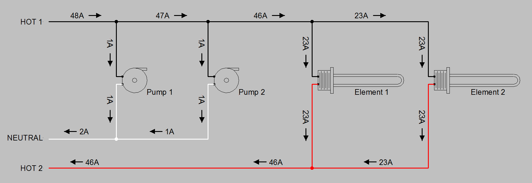
The drawing below shows how loop currents work. Since you will have multiple loops in your panel, you need to position the current sensing loop on the branch that carries all of the currents you are interested in.

Loop Current Example.PNG


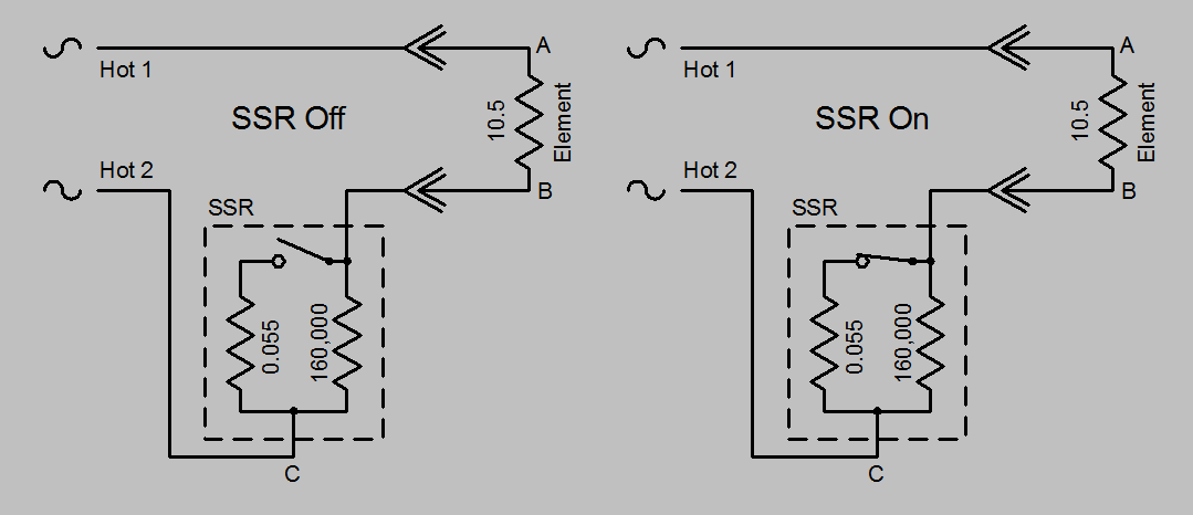
This next drawing shows an equivalent circuit for an SSR. When it is off it has a high resistance and only about 240/160,000 = 1.5 mA flow thru the SSR and element. The power in the element is then given by P=I^2 * R. Since the element resistance is about 10.5 ohms, the power when the SSR is "off" is 0.0015^2 * 10.5 = 0.000024 W.

SSR Model.PNG


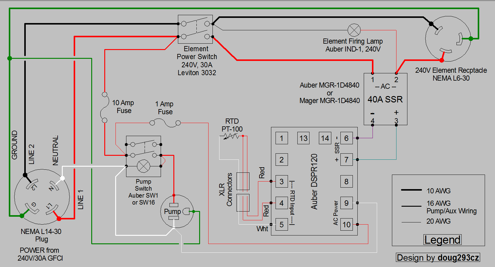
Here's a design I did previously that is close to what you are doing, but uses an EZBoil rather than a PID. You can substitute a PID, but the terminal assignments are different, so you will have to figure out proper terminals to connect for your PID.

DSPR120 1-Pump Simple.PNG


If you want to measure the current used by all loads in your panel, then you should run the red wire to the left of the 3032 switch thru the coil of the power meter. The voltage leads for the power meter connect to the red and black wires to the left of the 3032. If your fan is 120V, then it connects to the red wire to the right of the 3032 and neutral (white.)

I also highly recommend inclusion of the "Element Firing" lamp, as it will tell you if the SSR is operating correctly, or has failed in the "on" mode (which is the most common failure mode for SSR's.) SSR can fail temporarily due to excess temperature, or permanently do to internal component failure.

Your wiring of the spa panel looks correct, except that the white pigtail isn't connected the way you show it at the GFCI. Since this is prewired (and you can't change it) don't worry about that.

Brew on :mug:
 
Last edited:
You are correct that when the SSR is off that there will be 120V on the element, however, since almost no current flows thru the "off" SSR, there will be close to zero power going to the element. Power is only delivered when current flows. If you interrupt the current flow anywhere in a loop, then no power is delivered to the loop, even if there is voltage. This is why you only have to run one of the hot lines thru the SSR to control power.

The drawing below shows how loop currents work. Since you will have multiple loops in your panel, you need to position the current sensing loop on the branch that carries all of the currents you are interested in.

View attachment 685391

This next drawing shows an equivalent circuit for an SSR. When it is off it has a high resistance and only about 240/160,000 = 1.5 mA flow thru the SSR and element. The power in the element is then given by P=I^2 * R. Since the element resistance is about 10.5 ohms, the power when the SSR is "off" is 0.0015^2 * 10.5 = 0.000024 W.

View attachment 685392

Here's a design I did previously that is close to what you are doing, but uses an EZBoil rather than a PID. You can substitute a PID, but the terminal assignments are different, do you will have to figure out proper terminals to connect for your PID.

View attachment 685396

If you want to measure the current used by all loads in your panel, then you should run the red wire to the left of the 3032 switch thru the coil of the power meter. The voltage leads for the power meter connect to the red and black wires to the left of the 3032. If your fan is 120V, then it connects to the red wire to the right of the 3032 and neutral (white.)

Your wiring of the spa panel looks correct, except that the white pigtail isn't connected the way you show it at the GFCI. Since this is prewired (and you can't change it) don't worry about that.

Brew on :mug:

Thank you for the reply, its all making sense. There is one other question that I have, My current dryer is a 3 prong, with that being said, I can't run a 120v off of the panel. I decided to pull off the receptacle and take a look inside and I see that it actually has a 10/4 wire coming in, but only the 2 120 legs and the Ground/neutral are connected. In the back of the panel, there is a solid brass grounding wire coming off but not connected to anything (you have to zoom into the picture quite a bit). When I connect the bare copper wire to the neutral of the 3 prongs in resistance mode I am getting 0 ohms of resistance. In theory, this is fine for me to wire a 4 prong receptacle to the wiring and I wouldn't have any issues? What's throwing me off is in the spa panel and controller box I am building, the neutral and ground do not show any resistance when connecting the legs together. I am guessing since its replicating the 3 prong setup until it's grounded to a proper ground?
 

Attachments

  • IMG_20200617_153232.jpg
    IMG_20200617_153232.jpg
    945.7 KB · Views: 17
Thank you for the reply, its all making sense. There is one other question that I have, My current dryer is a 3 prong, with that being said, I can't run a 120v off of the panel. I decided to pull off the receptacle and take a look inside and I see that it actually has a 10/4 wire coming in, but only the 2 120 legs and the Ground/neutral are connected. In the back of the panel, there is a solid brass grounding wire coming off but not connected to anything (you have to zoom into the picture quite a bit). When I connect the bare copper wire to the neutral of the 3 prongs in resistance mode I am getting 0 ohms of resistance. In theory, this is fine for me to wire a 4 prong receptacle to the wiring and I wouldn't have any issues? What's throwing me off is in the spa panel and controller box I am building, the neutral and ground do not show any resistance when connecting the legs together. I am guessing since its replicating the 3 prong setup until it's grounded to a proper ground?
Yes, you should always measure near 0 ohms between ground and neutral, as they are connected together in your main breaker panel. That doesn't mean they are interchangeable however. In 120V circuits, the neutral is intended to carry the full current of the 120V load(s), and for this reason, code requires that neutral wires be insulated. Ground is only there for safety, and in normal operation should never carry any current. This is why ground wires don't need to be insulated.

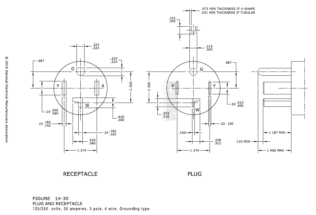
You can swap out the 3-wire receptacle for a 4-wire receptacle. In the 4-wire receptacle, the white neutral wire needs to be connected to the terminal labeled "W". The red and black hots go to the "X" and "Y" terminals, but it doesn't matter which goes to which. The bare copper wire then gets connected to the "G" terminal.

1592425416912.png


Brew on :mug:
 
Back
Top