New Electric Keggle Help

Homebrew Talk - Beer, Wine, Mead, & Cider Brewing Discussion Forum

Help Support Homebrew Talk - Beer, Wine, Mead, & Cider Brewing Discussion Forum:

This site may earn a commission from merchant affiliate links, including eBay, Amazon, and others.

zinger084

Well-Known Member
Joined
Jul 20, 2009
Messages
126
Reaction score
1
Location
Ohio
All,

I am looking to convert to an electric setup on my keggle (use inside this winter). I do simple extract brewing now and might go towards all grain in the future. Right now, I just want to get a 5.5kw element and turn my keggle into an electric keggle.

I have been doing some reasearch and read through The Pol's thread on his build, but I still need some help.

If I want to just convert my keg to electric, what exactly do I need?

http://auberins.com/index.php?main_page=product_info&cPath=1&products_ id=3
http://auberins.com/index.php?main_page=product_info&cPath=2&products_ id=30
http://auberins.com/index.php?main_page=product_info&cPath=2&products_ id=77
and the heating element (JB Welded and all)

????

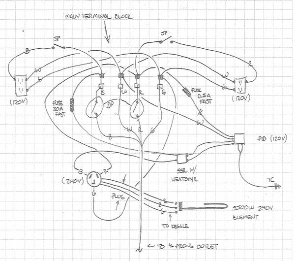
It would be useful to know schematically how this works out. Bring in power to the SSR, then to PID which is controlled by a thermocouple, ????

I am not 100% sure on this and still need more info...

What are the GFCI's for?
 
What are the GFCI's for?

Don't get too offended for me saying this. But.....If you are asking this question then maybe you should find someone local who can help you build this. 240v current is no joke. You should have a pretty good understanding of electricity before building your own device. Talk to a local electrician. Maybe have them look over your work before using it.

HBT is a good place to get help but most people who help you will assume you know the basics.

If you do and I am out of line. I am very sorry.
 
I am asking why people are using GFCI's on the controller box when you also put one in the main panel. (I'm a mech eng with electrical background). I just don't know exactly how the PID, themocouple, and SSR interact...
 
I am asking why people are using GFCI's on the controller box when you also put one in the main panel. (I'm a mech eng with electrical background). I just don't know exactly how the PID, themocouple, and SSR interact...

Ok sorry for that. You would not want to use two. It will not work. There should only be one GFI in your system. Either on the rig or at the panel.

PID sends pulses of low voltage to trigger relay. Relay then cycles the High voltage to element on/off. The thermocoupler just monitors the temp so the pid knows when to start/stop pulses.

Most times you can power the pid with line voltage. You should not need a seperate source of power. I think Pol has diagram. I will look around. If not i can draw one up later today.
 
So can someone run me through how this control box works? Bring in 240VAC to PID. From PID, go with DC to SSR. Then from SSR to heating element? Where does the thermocouple fit in there? Is that sequence right?
 
So can someone run me through how this control box works? Bring in 240VAC to PID. From PID, go with DC to SSR. Then from SSR to heating element? Where does the thermocouple fit in there? Is that sequence right?

240v to the SSR. One leg. If your PID can handle 240v to power it then send also send power to the PID. The PID does not control the line voltage directly. That is the job of the SSR. The thermocoupler gets wire directly to the PID.

I will look for a diagram.
 
OK found this on google images.

This should give you a better idea.

diagram.jpg
 
Thanks for checking for a diagram. I am going to order the parts listed in the OP, but I want to make sure I know how this works. I have a general idea, but I'm not 100%.

Do you just pull one leg of power to the PID for power?

I thought you brought both legs of the 240V to the SSR?
 
That image is in Pol's thread, but I don't get it completely. That's 120V power, not 240V (unless the white should be red in that diagram).

I get the PID and thermocouple, but still missing the SSR wiring. Why not both legs of power? If only one leg, won't the other be active always?
 
You can buy an SSRD or use two SSRs or use a DPST to switch both legs.

An SSR is just built to control one, that is all.

The element will not heat with one leg cut, but there will be current there.

I used the DPST as my main switch to power the element, the PID is simply the fine control AFTER the DPST
 
OK, I got it. Yay!

I am going to roll with two SSRs or one SSRD, whichever is cheaper. Thanks for the help guys... I think I am good to blow some more money on HB.
 
I would also suggest placing a switch that will cut power to the element regardless of the PID commands too. Why? The PID doesnt have an ON/OFF button and you basically have to mess with the program you have it running, to get it to stop sending the signal to power the element.

If you have a switch upstream, then you can turn the element on and off without the need to play with PID settings.
 
That image is in Pol's thread, but I don't get it completely. That's 120V power, not 240V (unless the white should be red in that diagram).

I get the PID and thermocouple, but still missing the SSR wiring. Why not both legs of power? If only one leg, won't the other be active always?

There is not a neutral in 240v power. You don't need one unless your appliance pulls off a 120v leg to power say controls. So in most situations you can use standard 10/2 wire for 240v. You would use the white wire as your second hot.
 
There is not a neutral in 240v power. You don't need one unless your appliance pulls off a 120v leg to power say controls. So in most situations you can use standard 10/2 wire for 240v. You would use the white wire as your second hot.

I see, but I am sure it's safer as well as code to use 4 conductor wire for 240VAC.

Also, if there is no neutral in 240VAC (since they are out of phase and return through each other), why are two SSRs safer than one since they return through each other?
 
I see, but I am sure it's safer as well as code to use 4 conductor wire for 240VAC.

Also, if there is no neutral in 240VAC (since they are out of phase and return through each other), why are two SSRs safer than one since they return through each other?

You are looking at it wrong. It is no safer to have the extra neutral wire. Code rules for wiring is the size of wire based on amperage, not how many wires you have. THERE IS NO NEUTRAL ON 240v. It does not use one. Adding a 4 conductor wire does not mean that now your 240v will use it. It will only use the fourth wire if you split one leg and use it to power something 120v.

The reason 2 SSR's are safer is you are now cutting power to both legs not just one, like Pol explained.
 
You are looking at it wrong. It is no safer to have the extra wire neutral. Code for that is the size of wire based on amperage. There is no neutral on 240v. It does not use one. Add a 4 conductor wire does not mean that now your 240v will use it. It will only use the fourth wire if you split one leg and use it to power something 120v.

The reason 2 SSR's are safer is you are now cutting power to both legs not just one, like Pol explained.

Makes me wonder why my 240VAC stove mentioned if it was a new installation, you should use 4-wire.

Sooo... let's recap. If I am only cutting the power to one leg of the 240VAC, won't the other leg be "powered" and heating when plugged into the wall by returning through the ground wire attached to the steel keg? Or does it need to return through the other leg of 240VAC?


Your stove probably has a clock and a timer. That requires 120v. That is why you have a neutral.

Yes your other leg will be powered BUT not heating. That is why Pol is telling you to use a switch. Just to be safe because the second leg will be powered. Using 2 SSR's will cut power to both.

I am not sure how else to explain how 240v works. You might want to brush up on Wikipedia or something.
 
Just seems weird they wouldn't make everything on the stove 240 to cut down on copper wire costs.

I understand though and I think I am going to go with one SSR and get a DPST switch to kill everything (in addition to unplugging it when I am done).
 
Thanks for the refresher...

Also, this is basically the same thing I found...

"Usually the power from the utility pole transformer has three output wires. One is usually bare metal, this is the neutral, and the other two are insulated, these are both hot but 180 degrees out of phase. When either one of these hot wires is combined with the neutral it is 110 volts.
When the two hot wires are combined it is 220 volts. A 220 volt breaker is a double pole breaker that switches both hots. If your neighborhood has a standard dual voltage transformer 110/220, then yes, any single hot line is 110 volts."

I knew they were split 180 OOP, but I didn't know they return through each other.
 
240v has two hots (black and red) and a ground. That's it.
I ran 4-wire to my setup because I needed to run 120v to my outlets for pump and stir motor. Those require a white neutral, so I have to have the 4th wire. Basically i took one of the hot wires (red) and paired it with the white (and a ground) to create a 120v circuit.

Like Brewmoor said, your range is much like my brew system - it has parts to it that run 120v and require the 4th neutral wire.
 
I agree... so it sorda seems stupid if you plan on expanding the brew setup in the future to run a 3 conductor 240v wire because you cannot make 120v without having to use the ground as the neutral.


Also, after reading this:

"Suggested fuse sizes:
PID Controllers - 0.25A Fast Acting (Auber suggests 1A Slow Blow but that is way too much in my opinion.)
SSR - For the supply side of the SSR use a Fast Acting fuse equal to or less than the rating of the SSR. Devices being switched by the SSR will need individual fuses should they be protected."

Do you need to put fuses on both sides of the PID's and the SSR's?
 
OK found this on google images.

This should give you a better idea.

diagram.jpg

So here's a good one then... in this picture, it looks like the PID is being powered by 220v (if the power source is coming from a double pole circuit breaker)???

Can you power this PID with 220v? Would I need to power it with 110v?
http://auberins.com/index.php?main_page=product_info&cPath=1&products_id=3

It appears so, but would like someone to chime in...
"Power supply voltage rating: 85~264VAC/50~60Hz."
http://auberins.com/images/Manual/Manual%20version%203.4.pdf
Page 2...
 
I agree... so it sorda seems stupid if you plan on expanding the brew setup in the future to run a 3 conductor 240v wire because you cannot make 120v without having to use the ground as the neutral.

Yeah you can look at it that way. Just be careful. If you are using a 30 amp circuit and a 5500 watt element you will be drawing about 26amps. Pumps can draw a lot of amperage. You might want a dedicated 120v circuit for pumps. Same goes for a second element, say for a HLT or something down the road. 1500 watt element will draw over 10 amps. You would not want to run that on same 240v circuit you are using for the boil kettle. Just make sure you plan for the amperages you will need.

Also NEVER try to use a ground as your neutral. NO NO NO.

Oh yeah. You should be fine powering that PID with 240v
 
240v has two hots (black and red) and a ground. That's it.
I ran 4-wire to my setup because I needed to run 120v to my outlets for pump and stir motor. Those require a white neutral, so I have to have the 4th wire. Basically i took one of the hot wires (red) and paired it with the white (and a ground) to create a 120v circuit.

Like Brewmoor said, your range is much like my brew system - it has parts to it that run 120v and require the 4th neutral wire.

So did I. 4 wires in so that I could power 120VAC equipment from the panel as well as the 240VAC for the element.
 
Yep, I would never use ground as my neutral and never have. I have been doing 110v wiring since I was pretty young, but never really delved into 220v...

It might be better to run the 120V pumps in the future on separate lines so I don't have to run say a 40 or 50amp line...

That electrical article really cleared up 220v for me... I really thought you needed a neutral for completing the circuit... learn something every day...

So, I think to keep the wire cheap, I am going to run a 10/2 line since I can power the PID with 220v and I plan on using other circuits for pumps in the future (way in the future)...
 
Keep in mind, a March 809 only pulls like 1.2A, so they are pretty minimal on the draw. You can run two of them for less than 3A.

I can run my pump and my 5500W element and I am under 25A. I have no reason to run the HLT while I am boiling, so that would never be an issue. I could run 2 809's and the 5500W element for under 26A.
 
So I am getting these main items for Christmas (yay!) and I wanted to know what type of fuse holders people are using to protect their PID and SSR? Blade type fuses? etc...?
 
So here is my wiring diagram. I'm not an EE, so I don't know typical symbols, so I labeled them.

Setup3.jpg


The extra GFCI's are for future pumps, etc...

Does anyone see anything wrong?

Will I need anymore fuses?
 
I would put your dp switches on the other side of the terminal. i would have them control power to the element/ssr. The way it is drawn now, if you turn the switch off, you lose power to the pid, and outlets. ( If i understand your diagram)
 
I would put your dp switches on the other side of the terminal. i would have them control power to the element/ssr. The way it is drawn now, if you turn the switch off, you lose power to the pid, and outlets. ( If i understand your diagram)

Yes, that is correct. I was using it as a main power shut down. Should I be using it the way you state so that I can still have power to my SP switches for the GFCI outlets, but kill the element power leg?

Would it be beneficial to put two DP/DT switches on there... one where shown, and the other where you mention? I would like to be able to have a master kill switch on there, but not sure what its doing right now besides mimicking pulling the plug out of the wall...

Also, do you see the need for anymore fuses? Are the fuse sizes/type correct?
 
I am by no means an expert, ( I am putting my first electric together now),but I really don't think you need switches to cut all power in. Just like you said, it is just like unplugging the wires from the outlet. I would suggest putting a dp switch to cut power to the SSR and element. Then, you still have use of the PID. You can use the PID to display temp as you are cooling.

I do not think you need any more fuses, as a matter of fact, IMHO, I do not think you need the 30 amp fuses. The 30 amp breaker should suffice.

I think I will use the DP/DT switch like you mention to cut power to the SSR and Element. That way I can still keep the PID for temp during cooling and use the 120V GFCIs.
 
Ok, I have this thing wired up and powered up Saturday. I think that the PID still needs setup though. When the set temp was lower than the reading temp, it was sending current to the element. Is there something I am missing? Is there a general setup that everyone does (manual to auto, percentage, etc... no clue)?
 
Ok, I have this thing wired up and powered up Saturday. I think that the PID still needs setup though. When the set temp was lower than the reading temp, it was sending current to the element. Is there something I am missing? Is there a general setup that everyone does (manual to auto, percentage, etc... no clue)?

Where did you buy it? Have a manual? There is some setup involved.
 
I bought it from Auber. I am not 100% up on the electronics portion of things, and I briefly read through the manual. Is there a few pointers you might have?
 
Well, if you are getting an output when your PV is HIGHER than your SV, then you must be in manual mode (% output).

I will have to look, my PID settings are posted here on HBT somewhere... let me look for them. Yooper has my old rig now so I cant go look them up.

EDIT: I cant find the post, it was a response to someone elses thread about 6 months ago...

You need to determine if you are in MANUAL mode or AUTO mode. I sold my manual with my rig as well, so I am of little help.
 
For your PID to be sending an output, when your SV is lower than your PV, you have to be in manual mode.

Are you comfortable with alternating between manual and auto modes?
 
Back
Top