New eBIAB build, questions about controls

Homebrew Talk - Beer, Wine, Mead, & Cider Brewing Discussion Forum

Help Support Homebrew Talk - Beer, Wine, Mead, & Cider Brewing Discussion Forum:

This site may earn a commission from merchant affiliate links, including eBay, Amazon, and others.

The_Bishop

Well-Known Member
Joined
Dec 8, 2013
Messages
2,100
Reaction score
676
I've decided to switch from my Avantco 3500 induction setup, and build a recirculating eBIAB kettle.

So far I've got most of the kettle components. Bayou Classic 15.5 Gallon kettle, 5500 watt all stainless ripple element, triclover element mounting hardware, bag, recirculation port, etc.

The hardware side I'm not worried about.

I'm in the process of planning out the controller.

My questions:

Where is everyone sourcing the parts? Prices seem to be all over the place.

Someone mentioned using a 3 position 25 amp switch to control power to the element. An on-off-on switch, center off. Position one is full 220v to SSR/element. Center is off. Position two is 120v to the SSR/element. The idea is using lower wattage for recirculation/mashing would prevent any scorching. None of the control panels I've seen have this feature, so I'm wondering if I'd be better served by just having a contactor and switch to kill power to the SSR/element. Has anyone had any scorching issues while recirculating during the mash?

I'm also considering using both a PID and the Auberin Digital SSR power regulator to control the SSR/element. My idea is to have the control wires for the SSR run to a DPDT toggle switch, with one side being the PID (for strike/mash/etc) and the other being the power regulator (for the boil). Thoughts?

Is a 220v breaker necessary in the control panel? Or is it redundant with the breaker in the main panel?

I've got tons more questions but those will get me started.

parts.jpg
 
I've decided to switch from my Avantco 3500 induction setup, and build a recirculating eBIAB kettle.

So far I've got most of the kettle components. Bayou Classic 15.5 Gallon kettle, 5500 watt all stainless ripple element, triclover element mounting hardware, bag, recirculation port, etc.

The hardware side I'm not worried about.

I'm in the process of planning out the controller.

My questions:

Where is everyone sourcing the parts? Prices seem to be all over the place.
Sounds exactly like what I plan to build. Most common sources for electrical parts are Auber, ebay, and amazon. Probably want to avoid Fotek SSR's as there are a lot of counterfeits on the market, and the counterfeits have a very high failure rate. Most popular PID's are Auber 2352/2362 and Mypin TD4.

Someone mentioned using a 3 position 25 amp switch to control power to the element. An on-off-on switch, center off. Position one is full 220v to SSR/element. Center is off. Position two is 120v to the SSR/element. The idea is using lower wattage for recirculation/mashing would prevent any scorching. None of the control panels I've seen have this feature, so I'm wondering if I'd be better served by just having a contactor and switch to kill power to the SSR/element. Has anyone had any scorching issues while recirculating during the mash?
I think I would do this with a couple of contactors and a low amp three position switch. It's only one extra contactor, as you need at least one for positively cutting power to the element anyway.

I'm also considering using both a PID and the Auberin Digital SSR power regulator to control the SSR/element. My idea is to have the control wires for the SSR run to a DPDT toggle switch, with one side being the PID (for strike/mash/etc) and the other being the power regulator (for the boil). Thoughts?
This will work fine, and is what I plan on doing.

Is a 220v breaker necessary in the control panel? Or is it redundant with the breaker in the main panel?
Only if the wiring in the panel is rated for lower amps than the breaker. You probably want fuses/breakers for some of the lower power items so that you can use thinner wiring, which is easier to work with, for them.

I've got tons more questions but those will get me started.

Since it sounds like you want pretty much exactly what I do, I will go ahead and put together a schematic for it. Watch this space.

Brew on :mug:
 
Thanks, I'll keep my eyes peeled.

What are you using to generate schematics? I usually do a very technical pencil and paper scribble, but having something a bit more 'professional' looking would be nice.
 
Thanks, I'll keep my eyes peeled.

What are you using to generate schematics? I usually do a very technical pencil and paper scribble, but having something a bit more 'professional' looking would be nice.

I use a CAD program, which unfortunately is no longer available. But, any CAD program can be used.

Brew on :mug:
 
Pulled the trigger on the Auber PID and Boil control, as well as the 40A SSR and the heat sink. Since I *know* I'll need those parts, got them on the way.
 
Ok, new question in reference to PID/ssr function:

When the PID detects that the temperature is below threshold and triggers the heater, does it kick it on 100%, or at a power level commensurate to the amount of temperature change required? If it matters, the PID is an Auber SYL-2352, with a 40A SSR.

PID stands for Proportional, Integral, Differential control. The proportional part adjusts the output based on how far the process (actual) value is from the setpoint. The integral part adjusts the output based on both how big and how long the deviation from the setpoint is. The differential part adjusts the output based on how fast the process variable value is changing.

When controlling an SSR the output is varied using a pulse width modulation scheme. There is a fixed cycle time and the proportion of that cycle time when the SSR is turned on is varied. For lower output, the SSR is on for a shorter fraction of the cycle time.

Brew on :mug:
 
We'll probably be double talking a bit with the two different threads, but now I see more of the overall question you were trying to address in the other threads. Probably a good idea to have a mod merge the threads.

I know the question is seeded from our chat at the shop where I showed you my first controller build. As I mentioned in the other thread, with a single vessel system used for mash and boil, the high power element can be a scorching liability if you're not careful. While switching between 240 and 120v works great for me, it would be nice to have easy access to granular control of max power output rather than 5500w and 1375w. The 2352 has the OUTH setting in the menu for granular control but it fails on the "easy access" portion.

My next panel is based on the Brew-Boss board. However, before I changed plans, it was going to be the 2352 and the Power Regulator in series control. It requires two SSRs or a dual channel SSR, but it provides a lot of control.
 
The two SSR idea occurred to me, but now the heat sinks require more real estate on the control panel, and I'm trying to keep the footprint down a bit. I was also concerned about the PID's ability to adapt to the output of the heating element being different from what it's learned behavior is during the auto tune process.
 
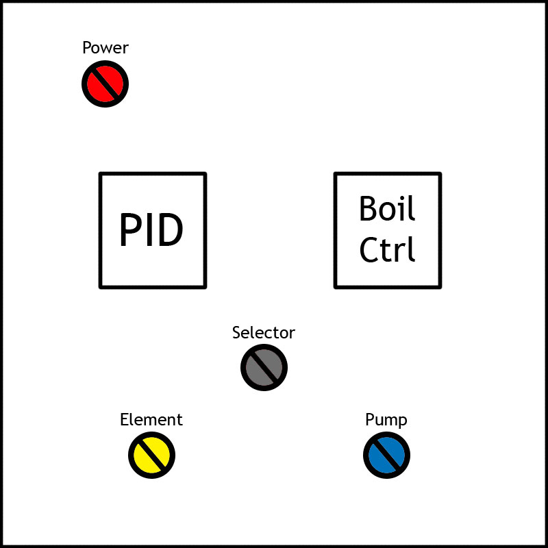
Ok, so as a part of figuring out what parts I need, I did a quick mock-up sketch of the panel. I'm figuring on an 8 x 8 box.

Power is main panel power, running to a 220v contactor.

PID and Boil Control are self-explanatory.

Selector will be a DPDT switch that toggles control of the SSR between PID and Boil control.

Element is main power to the element, connected to a 220v Contactor, which then supplies the SSR. Considering doing a 3 position switch here that will allow me to select 110v to the element, off, and 220v to the element. Need to do a bit more research on how I can do this with contactors, may need a DPDT contactor in addition to a standard 220v contactor to make this possible.

Pump switches power to the pump. Don't think this needs a contactor, as it's a low load and the switch should handle it.

Control-Panel.jpg
 
PID and Boil Control are self-explanatory.


I'm curious to know (Newbie on electric brewing systems myself) why boil control is necessary? Don't most PIDs used in these systems have a manual option that sets a % for boil control? Wouldn't a single PID, on/off switch for pump and a main on/off switch work for the panel you are looking for?
 
Yes, the PID has a built in manual mode, but the resolution is a little on the coarse side of things. The boil control has a much finer and quicker range of adjustment, as well as being more intuitive to use.
 
Yes, the PID has a built in manual mode, but the resolution is a little on the coarse side of things. The boil control has a much finer and quicker range of adjustment, as well as being more intuitive to use.


Ah gotcha that makes sense. I also like your idea of a 3 position switch to control voltage to the element. I'm curious to hear more about how you at pulling that off.
 
Ok, here's the first pass at a controller that switches between 120V & 240V for the element, and between PID and DSPR1 for SSR control. Let me know if you have questions or find any errors.

PID DSPR1 Pump 240V.PNG

Brew on :mug:
 
Ok, so as a part of figuring out what parts I need, I did a quick mock-up sketch of the panel. I'm figuring on an 8 x 8 box.

Power is main panel power, running to a 220v contactor.

PID and Boil Control are self-explanatory.

Selector will be a DPDT switch that toggles control of the SSR between PID and Boil control.

Element is main power to the element, connected to a 220v Contactor, which then supplies the SSR. Considering doing a 3 position switch here that will allow me to select 110v to the element, off, and 220v to the element. Need to do a bit more research on how I can do this with contactors, may need a DPDT contactor in addition to a standard 220v contactor to make this possible.

Pump switches power to the pump. Don't think this needs a contactor, as it's a low load and the switch should handle it.

I just built an E-Kettle system and control panel. Being an electrician the panel was the easy part. I've built a lot of control panels in my life and I would suggest a larger enclosure. 8 x 8 will get very busy and will be a challenge to wire.

This is the enclosure I used. Search my profile for the thread I have on my build. It shows my panel.

Good luck.

http://www.amazon.com/gp/product/B005T94MQU?psc=1&redirect=true&ref_=od_aui_detailpages00
 
Last edited by a moderator:
Ok, here's the first pass at a controller that switches between 120V & 240V for the element, and between PID and DSPR1 for SSR control. Let me know if you have questions or find any errors.


View attachment 331005


Brew on :mug:


Need to make sure the SW1 is switched slow enough that the mechanical relays are not closed simultaneously. Might think that wouldn't be possible but mechanical relays, especially large coiled ones, take a few more ms to release than to energize.
 
Doug, that looks great! It's pretty much what I've been sketching out on paper, but a lot neater. I wish I had software to turn out the schematics like that.

I'm still not convinced that I need to switch the power on the element, though. It's an ULWD ripple element, only 60 watts per square inch.

Anyone have personal experiences to share? Not switching element voltages simplifies the panel a significant amount, and knocks down the price a bit. As much as I'd love to build a 'no expense spared' rig, my finances say 'Slow down, cowboy.'

That's what i was wondering. Being new at this I have a 4500 watt ULWD ripple element and it controls very good and no scorching. The element even after a 90 minute boil cleans off with a rag.

I have the same controller as yours and to go to manual and set for a boil is straight forward and simple to use and controls well. Not sure if the cost is necessary but I'm new to the E-Kettle. Let me know if I'm missing something.
 
Probably, the boil control is overkill. What I like about it is the logging and repeatibility of boils with it; I can log boiloff based on percentage of power applied. It also does away with the 'pulsing' boil you can get with a strictly PID controlled element due to the resolution of control it gives.

I figure I'll do it with straight voltage to the element, and skip the variable voltage switch. It's easy enough to add it in later if it becomes an issue, or I can use another option that Bobby_M mentioned and use two SSRs utilizing the boil control to adjust element power via the second SSR.

Doug, I hate to ask it, but could you do one more schematic without the switching voltage to the element?

My current plans include a 220v 30a breaker in the box, as well as a 110v 6a breaker, with the 6a breaker providing pump power, lights, etc. Sounds about right?
 
...

Doug, I hate to ask it, but could you do one more schematic without the switching voltage to the element?

My current plans include a 220v 30a breaker in the box, as well as a 110v 6a breaker, with the 6a breaker providing pump power, lights, etc. Sounds about right?

It's easier to take things out of a schematic than add them (or start from scratch.) I added a fuse in front of the main power key switch for added safety. I replaced the three way voltage selection switch with a lighted element power enable switch, so eliminated the discrete element power enabled lamp. Using a breaker in place of the 10A fuse is a good idea.

PID DSPR1 Pump 240V only.PNG

Brew on :mug:
 
If you already have a 30 amp breaker upstream, there's no reason to add another one in the box. The pumps and other accessories can be protected with cheap inline or panel mount glass fuse holders. With a single "element enable" switch and contactor used, there's no problem using a PID's manual control (but you need the 2352 for that). I wouldn't say that I get any pulsing at a typical 50-65% output. Limiting to only one 16th DIN box really simplifies the design and uncrowds the box. I don't think the power regulator, when used ONLY for boil control, is that much of an advantage.
 
Doug: Thanks a *million*. Owe you a beer or ten.

Bobby: Point taken, no reason for a breaker in the panel. Also, makes sense about the fuse holders; they can be put in a place that doesn't require panel opening to check/replace.

I do have a 2352 PID coming in. However, the boil control is in the same box, along with the SSR and heat sink. I'll run with the plan as is depicted in Doug's last schematic. It's not adding much; a DPDT switch and a few extra wires.

Now on to ordering the rest of the parts...

Thanks for helping me empty out my wallet, fellas! :mug:
 
If you already have a 30 amp breaker upstream, there's no reason to add another one in the box. The pumps and other accessories can be protected with cheap inline or panel mount glass fuse holders. With a single "element enable" switch and contactor used, there's no problem using a PID's manual control (but you need the 2352 for that). I wouldn't say that I get any pulsing at a typical 50-65% output. Limiting to only one 16th DIN box really simplifies the design and uncrowds the box. I don't think the power regulator, when used ONLY for boil control, is that much of an advantage.

I believe the SYL-2362 now contains manual mode: http://www.auberins.com/index.php?main_page=product_info&cPath=1&products_id=106. It also contains two relays (for alarms, etc.) vs. one for the 2352. The only thing the 2362 doesn't have is voltage or current process sensor inputs (RTD or thermocouple only.)

Brew on :mug:
 
Doug: Thanks a *million*. Owe you a beer or ten.

Bobby: Point taken, no reason for a breaker in the panel. Also, makes sense about the fuse holders; they can be put in a place that doesn't require panel opening to check/replace.

I do have a 2352 PID coming in. However, the boil control is in the same box, along with the SSR and heat sink. I'll run with the plan as is depicted in Doug's last schematic. It's not adding much; a DPDT switch and a few extra wires.

Now on to ordering the rest of the parts...

Thanks for helping me empty out my wallet, fellas! :mug:

You're welcome.

The SYL-2352 will work just fine. Be aware that the connections are different between the 2352 & 2362, so don't go by the connection numbers in the schematic.

Brew on :mug:
 
If you already have a 30 amp breaker upstream, there's no reason to add another one in the box. The pumps and other accessories can be protected with cheap inline or panel mount glass fuse holders. With a single "element enable" switch and contactor used, there's no problem using a PID's manual control (but you need the 2352 for that). I wouldn't say that I get any pulsing at a typical 50-65% output. Limiting to only one 16th DIN box really simplifies the design and uncrowds the box. I don't think the power regulator, when used ONLY for boil control, is that much of an advantage.

I agree with you on the extra breaker. You must be using a GFI up front now so no need for an additional breaker.

As for the controller I have the same unit, the SYL 2362 and I can switch to manual mode if it's set for PID so his controller would work. One more thing on manual mode is if you locate your temp sensor in the piping for your pump you do not need the sensor for manual mode. If the sensor is in the line and you are using the PID or other option you will need to circulate during the boil.
 
Doug: Yeah, I figured the wiring locations may be different. No big deal.

Yeah, I'll be putting in a shiny new 30A plug in my brew area (Garage) with a GFCI breaker in the main panel (also in the garage, bonus). I like my life minus the 'sparks'.

For now I'm thinking I'll put the probe in the kettle outlet and see how it goes from there; it's easy to change if it doesn't work out well there but I'm not anticipating any wild issues. The only times I need to really control temperature it'll be when I'm circulating anyway.
 
Yeah, I get that! I must have thought and re-thought about positioning.
 
I reworked the designs to eliminate one of the contactors in each. The new ones are below.

Switchable between 120V & 240V to the element:

PID DSPR1 Pump 120V or 240V rev 2.PNG

240V only to the element:

PID DSPR1 Pump 240V only rev 2.PNG

Brew on :mug:
 
So I've been working on my brew panel layout.

Pretty sure I'm happy with this one, only changed it a dozen times or so. :cross: :)

The light gray area shown is the 'workable' area of the door, avoids the seal and lip of the enclosure.

The yellow 'element' is an indicator that's wired into the element so I can see when it's firing.

'Power', 'Pump' and 'Heat' are lighted push button switches.

Everything is to scale.

Any feedback?

Panel-Layout.jpg
 
Last edited:
So I've been working on my brew panel layout.

Pretty sure I'm happy with this one, only changed it a dozen times or so. :cross: :)

The light gray area shown is the 'workable' area of the door, avoids the seal and lip of the enclosure.

The yellow 'element' is an indicator that's wired into the element so I can see when it's firing.

'Power', 'Pump' and 'Heat' are lighted push button switches.

Everything is to scale.

Any feedback?

Aren't you missing a switch? How are you selecting whether the PID or Power Controller will drive the SSR?

Brew on :mug:
 
Maybe he's running them in line as I suggested.

The drawing doesn't look like an SSR in series with SSVR is being used. An SSR driven by a PID in series with an SSR driven by a DSPR1 wouldn't work very well as you would need to sync them up somehow, since the DSPR1 doesn't operate in phase angle mode.

Brew on :mug:
 
My current plan was to run it as Bobby suggested, PID running one SSR gated through another SSR controlled by the DSPR1.

Assume I'm an idiot (I'm not, entirely) and explain what's wrong with that setup, please? I was under the impression that the PID would trigger the first SSR to power up the element, and the second SSR/DSPR would regulate the percentage of the power to get through via pulsing SSR.

If I'm wrong, it's easy enough to fix as it's just a drawing at this point.

I'm not sure how to explain it easily. If you read the appendix in the DSPR1 manual it may help understand why putting these in series may cause problems.

Brew on :mug:
 
The concern is that the SSR turns on when the AC wave crosses 0v. So if your PID is generating very short pulses, the SSR controlled by the boil control may not see enough AC cycles to turn on as much as the controller thinks it is.

The boil controller is taking the mains frequency via its power supply to synchronise its firing of the SSR.

You may have more success using one of the alternative modes that the DSPR offers over the stock burst mode. Equally you could put the PID into manual mode and set it to 100%, or set the SV to something like 250f which should have it firing 100% output anyway.

IIRC the last suggestion was Bobbys, as if the PID SSR is being held on then the boil control SSR will get the full AC waveform so no worries.

The edge case is if you were trying to use the PID to hold an established temperature and also dial down the element power with the DSPR. In which case you may see substantially less output than you'd predict due to the phasing issue

^^^ Yes.

I think it is cleaner to switch the control inputs to the SSR between the PID and DSPR1. Then there is no ambiguity about just what the waveform to the element looks like. Also, the SSR's have a max forward voltage drop specified as 1.5V meaning if you have 240V power, the element may only see 238.5V. With two SSR's in series, the element may see only 237V. So, max element power is slightly reduced. Maybe more of an issue is you now have two SSR's dissipating heat instead of one, so you need more cooling for the SSR's. Nothing insurmountable, just more little things that make the series SSR solution less than optimal IMO.

Brew on :mug:
 
Back
Top