Teckademic
New Member
- Joined
- Oct 13, 2019
- Messages
- 4
- Reaction score
- 0
ops sorry about that. I had too many tabs open when I posted. Wrong place.This thread is for the ESP8266 BrewPi firmware - are you trying to connect a Tilt to Fermentrack?

ops sorry about that. I had too many tabs open when I posted. Wrong place.This thread is for the ESP8266 BrewPi firmware - are you trying to connect a Tilt to Fermentrack?
I put together a 2nd ferm cooler recently, its a smaller commercial cooler that's a bit underpowered for forced cooling (but great at maintaining). My problem is with a 10 min deadband on a ripping fermentation the temp runs away before the control can take any action, causing huge swings. All this is happening at lager temps in the mid 40s, I can't imagine what would happen at ale temps. I have played with the control constants and with out a shorter dead band it doesn't make a difference. Can I shorten the dead band in fermentrack?
Thorrak - Awesome job with this project, have had one running for a while after having moved from Brewpi. I was wondering, is there any way to recover an iSpindel calibration from a non running installation? Or recover the configuration into a new install? Just did my iSpindel calibration a week ago, and been meaning to make a backup of my whole SD Card. Had a power outage last night and found out my Pi wasn't on the UPS and hosed it.. I can read the card fine and see everything, just cant boot off it, so hoping there's a way to recover my calibration data. Is that stored anywhere accessible or is it in a DB?
Hey All! I am a huge fan of Fermentrack and Thorrak was super cool and was interviewed on my podcast about Fermentrack. If you want to get some of the background and his thinking on the project it is a great listen.
https://homebrewingdiy.beer/index.php/2019/10/10/episode-7-fermentrack-part-2-with-jon-beeler/
It was my pleasure!!! I can't wait to see some of your future projects!It was loads of fun recording this with you - thanks for the opportunity!
If you're running the default install configuration, then the file you'll want to save is the /home/fermentrack/db.sqlite3 file. There's a bunch of apps that can be used to read sqlite3 files - I just randomly searched and found this one (though I've never used it).
You MIGHT also be able to get away with installing Fermentrack, overwriting the db.sqlite3 file on the new install with the one from the old install, and also overwriting the
/home/fermentrack/fermentrack/fermentrack_django/secretsettings.py file with the one from the new install, then rebooting the Pi. No guarantees, but it might work!
Hi Thorrak (and everyone!),
Is anyone else interested in running Fermentrack on macOS?
I've been working on "porting" Fermentrack to run on macOS instead of a pi. My reason is:
* Stability -- my pi seems to crash regularly after a period of time. I'm not sure why. Pi SD cards are also easily corrupted with power failures.
* Development - I can more easily work on Fermentrack on my Mac instead of schlepping things over to a pi. Running Djanjo from Visual Studio Code is just one-step to start debugging!
* Use existing hardware. I know, a Pi is relatively cheap, and I bought one for this project, but I already had an iMac on my network.
* Most the peripherals are now wireless, so we don't seem to need dedicated hardware with a server wired to the fermentation chambers.
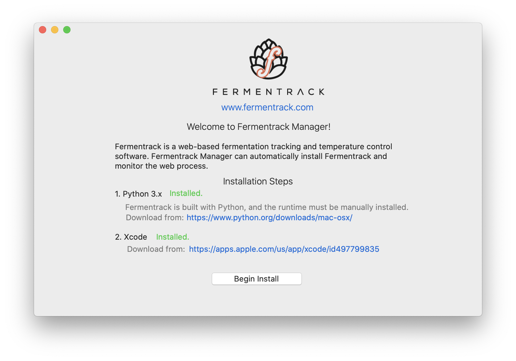
I wrote a macOS LaunchDaemon that does the following:
1. Runs an embedded copy of redis
2. Runs circusd
3. Runs Apache via python3 runmodwsgi -- I didn't want to have to install nix, and macOS comes with apache. runmodwsgi is super easy to isolate and run alone.
The daemon keeps an eye on these three and relaunches things in case of crashes.
My mods to Fermentrack are minimal; I wrote a BLE connection script, and made a few minor tweaks.
My next step is to create a one-step installer for all this stuff. I'm planning on having a simple Mac app that allows anyone to install Fermentrack on it and setup the daemon. Screen shot attached of what I'm working on.
I'll push the source to GitHub at some point...but I'm curious if anyone else would find this stuff useful. It would also be nice to pushback my changes to the main Fermentrack repo at some point.
corbin
This is awesome!
How did you get Bluetooth working? While I do all my development on a Mac, Bluetooth basically had to be tested in “production” due to the way the daemon works.
is your RPI powered separately from the other components?
Probably 2 really simple questions that either everybody knows without asking, or has been covered, but I didn't find it.
On a scale of 1-10, what's the point of the PCB? I see how it would make things neater, but stuffed into a box, I don't see $15 worth of value in neatness for myself. I get thats for 4 PCB's, but I probably will only ever need 1 and even if I make another someday, it's still $15 admission.
This picture posted previously looks so easy to an electronics beginner and has no PCB. Other than neatness, is there any benefit to use the PCB instead of this?

And finally, speaking of neatness and cheapskatedness, why does everybody use outlets for these things? Why not cut the plugs off the freezer and heater cords, run the wires into the control box through a strain relief, and switch them directly? It's not like I will ever need my freezer to appear stock, and if you ever want it to be just a freezer can't you do that via single sensor fridge temp mode set below freezing? Even assuming a parts failure it would be a 2 minute job to disconnect the wires and re-attach the plugs, or $2 for a proper screw connection replacement plug. I understand outlets for commercial controllers, average Joes don't want to cut and wire stuff for products they pay for. But for a DIYer willing to build their own controller for a dedicated ferment chamber, it seems silly to add the outlets at all. At a quick glance wouldn't it just be a matter of wire nutting power cord, freezer cord, and heater cord neutrals all together, their grounds all together, and freezer and heater hots individually to the red wires coming from the relay? Is there a reason not to, or is it commonly done and just not shown on diagrams? It seems easier, cheaper (admitedly only $2), and neater so there must be a reason against it.
Thanks to everybody for this awesome project and thread!
")
On a scale of 1-10, what's the point of the PCB?
And finally, speaking of neatness and cheapskatedness, why does everybody use outlets for these things? Why not cut the plugs off the freezer and heater cords, run the wires into the control box through a strain relief, and switch them directly? Is there a reason not to, or is it commonly done and just not shown on diagrams?
Should the fact I don't know what this means worry me? I know the esp8266 is 3.3v, if you are talking about triggering the relays, see below. Or do you mean that resistors are needed to power the sensors?The ESP8266 runs internally on 3v3 (3.3 volts) so you would want to power everything from that terminal and change the resistor accordingly (I think 2.2k Ohm?).
The relays I'm using (link below) have been reported to work with 1.5-3.5v in reviews and questions.The relay is meant to be powered by 5V but I believe 3V3 will pull it down - you'd have to check. That is one of the benefits of the circuit board - it handles the voltage shifting.
Honestly I just don't feel like waiting for a PCB, $15 is a drop in the bucket for how much I've spent on HB gear, I get that. But amazon has 1 day shipping for the parts I need, and I can start tomorrow. Presumably if I have troubles and don't fry anything, I can always order the PCB then. Likewise if I decide I have to have a screen and the logic controller seems too messy to add.For me the ability to bypass a rats-nest and be able to troubleshoot effectively when needed far outweighs any small cost for a board. I mean really, it costs less than a beer.
I got you on the wire sizing, I built my 50A brewery so I know all about that! Speaking of, I realize I also built my controllers without all the plugs and outlets that people seem to use, and haven't regretted it. It's not like I ever need to plug those elements in anywhere else, and if I did it would be for a big enough reason to warrant some disassembly. The elements themselves are triclamped for easy removal from the vessel, but they are hardwired to the controller. 2x 30amp outlets and 2x 30 amp plugs just adds $, adds time, and takes up real estate.The same can generally be said for using an outlet vs. hardwiring your fridge/heater into the relay - outlets cost $2-ish and add flexibility, but can absolutely be skipped. Just be careful when sizing your cables as undersized cables can be a fire hazard (hence the reason people recommend not using extension cables with high-load devices like refrigerators).
If I had to choose between an outlet and an LCD, I would choose the outlet. If I had to choose between an outlet and a PCB, I would choose the outlet. Of course, I would choose all three - but that’s one of the great things about this project: you can adapt it to fit your specific situation and your specific goals.
Probably 2 really simple questions that either everybody knows without asking, or has been covered, but I didn't find it.
On a scale of 1-10, what's the point of the PCB? I see how it would make things neater, but stuffed into a box, I don't see $15 worth of value in neatness for myself. I get thats for 4 PCB's, but I probably will only ever need 1 and even if I make another someday, it's still $15 admission.
This picture posted previously looks so easy to an electronics beginner and has no PCB. Other than neatness, is there any benefit to use the PCB instead of this?
And finally, speaking of neatness and cheapskatedness, why does everybody use outlets for these things? Why not cut the plugs off the freezer and heater cords, run the wires into the control box through a strain relief, and switch them directly? It's not like I will ever need my freezer to appear stock, and if you ever want it to be just a freezer can't you do that via single sensor fridge temp mode set below freezing? Even assuming a parts failure it would be a 2 minute job to disconnect the wires and re-attach the plugs, or $2 for a proper screw connection replacement plug. I understand outlets for commercial controllers, average Joes don't want to cut and wire stuff for products they pay for. But for a DIYer willing to build their own controller for a dedicated ferment chamber, it seems silly to add the outlets at all. At a quick glance wouldn't it just be a matter of wire nutting power cord, freezer cord, and heater cord neutrals all together, their grounds all together, and freezer and heater hots individually to the red wires coming from the relay? Is there a reason not to, or is it commonly done and just not shown on diagrams? It seems easier, cheaper (admitedly only $2), and neater so there must be a reason against it.
Thanks to everybody for this awesome project and thread!

I think with your needs I would go with an STC1000+I got you on the wire sizing, I built my 50A brewery so I know all about that! Speaking of, I realize I also built my controllers without all the plugs and outlets that people seem to use, and haven't regretted it. It's not like I ever need to plug those elements in anywhere else, and if I did it would be for a big enough reason to warrant some disassembly. The elements themselves are triclamped for easy removal from the vessel, but they are hardwired to the controller. 2x 30amp outlets and 2x 30 amp plugs just adds $, adds time, and takes up real estate.
I picture a similar use case here. I'm not just building a controller for my freezer, I might as well be building a part of the freezer. I don't ever want the freezer to not have awesome controls. And if I want the controller somewhere else? That's why I'm building a spare
I'll make you guys a promise. If I hardwire everything and have some PITA to troubleshoot failure, I'll redo it right and clean and neat... and probably never have to open it up again!
As someone who previously had an STC1000+, even with everything hard-wired, without an LCD, I’d still go BrewPi.I think with your needs I would go with an STC1000+
Is the OP going to use his freezer to ferment in? From his last post, I got the feeling he was just using it for a serving vessel.As someone who previously had an STC1000+, even with everything hard-wired, without an LCD, I’d still go BrewPi.
Is the OP going to use his freezer to ferment in? From his last post, I got the feeling he was just using it for a serving vessel.
Is your beer really at its best if it isn’t served at exactly 33.2F?

What are you serving, the Silver Bullet? [Yeah, I assume your point was about the accuracy of serving temperature, but your choice of 33.2°F is pretty far from what I'd ever serve any beer.]Is your beer really at its best if it isn’t served at exactly 33.2F?
What are you serving, the Silver Bullet? [Yeah, I assume your point was about the accuracy of serving temperature, but your choice of 33.2°F is pretty far from what I'd ever serve any beer.]
I hadn't seen that thread, but I read through it a bit and get to:I think with your needs I would go with an STC1000+
HA!I still use a STC1000+ but there are better options out there now. Look at Fermentrack and the BrewPiLess threads on this board
I see the change, but can you explain why it is better? I understand electricity like I understand plumbing and baking, so lots of things obvious to electronic hobbyists go right over my head.I prefer powering DS18B20 with 5V and tie the pullup to 3.3V
like this:
fwiw, the pullup (to VCC) is on the anode of the optocoupler led, the signal is on the cathode (hence the low-active control).
If you want to make the setup bulletproof, remove the VCC-JVCC jumper and put 5V and GND on the appropriate pins to power the coils from 5V and relieve the 3.3V regulator from having to deal with the relays...
Cheers!
How much are the STC1000s these days?I still use my STC1000+ for mostly fermenting yogurt in a crockpot. I have versions of all of the BrewPi family. I normally recommend Fermentract as the first choice but you had lowcost listed as a priority and that was the main reason I suggested the STC1000+.
I have a couple pi B+ and arduino uno's laying around so I could have just gone legacy, but I'd lose out on networking, tilt and education. And I've got some other ideas for future projects using the ESP8266. So for the networking and experience I want something ESP8266 based.
I just kinda ended up here. It looks to me that all the popular ESP8266 projects use a more or less interchangeable basic design and could be flashed back and forth at will. But on the front end I've decided on fermentrack, so I came here because of the Thorrak commonality.
I see the change, but can you explain why it is better?
Totally lost me, I don't know pullup, VCC or JVCC. I'm googling now, but a simple explanation would be helpful. It sounds like you're saying it's a way to trigger the coils with 5v vs. 3.3v as originally shown, which may help longevity by not burning out the regulator. Which sounds good.
EDIT: I think I get it now. Pulling the jumper separates the relays into basically 3 parts: the signal from the board which basically just fires an LED which would still be 3.3 V, the low voltage side of the relays which is 5V, and the high voltage side of the relays would all be separated. So basically instead of powering and triggering the relays from the ESP, I would pull 5V from the power supply before it goes into the ESP. And if I understood my googling this would require NOT grounding from ESP to the relay board as shown via the euro connector, but rather ground the relays to the ground from the 5V supply?
I would be more than happy to use it, since I already have a Mac in my BreweryHere's the source on my fork!
https://github.com/corbinstreehouse/fermentrack/blob/master/gravity/tilt/tilt_monitor_macos.py
All I did was re-write tilt_monitor_aio.py to use CoreBluetooth via PyObjc; it was pretty easy (granted, I worked at Apple for many years on AppKit/UIKit). I didn't want to duplicate code, so I pushed common code to tilt_monitor_utils.py.
Eventually I'll look at my changes, clean things up, and make a pull request for the main repo.
I'm thinking I'll push the macOS "Fermentrack Manager" to a separate repository to keep things clean. I'll let you all know when I get it going well enough to have some other people start using it.
-Corbin
Nice getting it to work, while it sits powered on 
Enter your email address to join: