Looking for feedback CraftBeerPi Controller diagram

Homebrew Talk - Beer, Wine, Mead, & Cider Brewing Discussion Forum

Help Support Homebrew Talk - Beer, Wine, Mead, & Cider Brewing Discussion Forum:

This site may earn a commission from merchant affiliate links, including eBay, Amazon, and others.

failbeams

Active Member
Joined
Aug 25, 2011
Messages
36
Reaction score
0
Location
shingle Springs
Hey all,

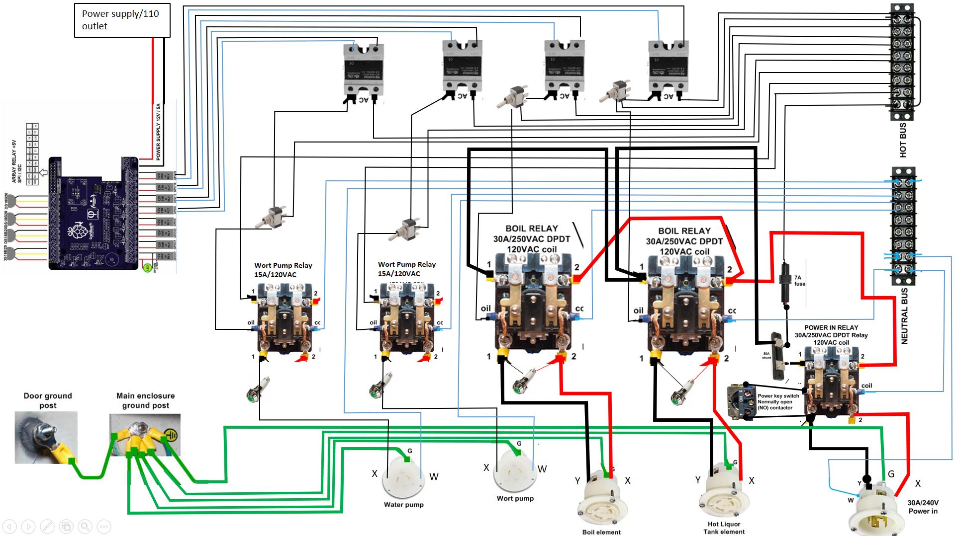
I have been very slowly piecing a new brewing system together, and have been recently focused on the controller. Its a eHERMS system, with 2 5500W heating elements and 2 pumps. I am planning on using a CraftBeerPi system with a 7 inch touchscreen for the "brains". I have been doing a ton of reading, as electrical work is not my forte. As such I was hoping to get some feedback from those with a little more experience.

I kinda tried to combine the basic concept outlined by the Electric Brewery website with what I've read about CraftBeerPi builds. I designed SSRs in series with EMRs to avoid an closed failure of the SSRs (seems to be common enough to worry about). I also included indicator lights for each load, which a lot of people didnt do but I though might be nice. Would probably use some small LEDs instead.

Any thoughts? Blaring errors? Constructive criticism is more than welcome.

Thanks in advance
Capture.JPG
 
Last edited:
  1. How are you controlling your heating elements? There are no SSRs in line with the output power.
  2. You can just use a single 5V power supply for your Volt and Amp meters.
  3. I see your contactors are daisy chained. This may work if you are running a 30A setup. A better practice would be direct runs from the distribution blocks.
  4. Your wort pump is in series with your light. This should be parallel as you have your heating lights.
  5. 7A fuse, have you checked your current draw to ensure this is correct? Dont want it to pop when you cut on power.
  6. What are the 2 extra SSRs? If they are used see #2. Oops I see now, you are using the PI to drive the SSR, to turn on the coil right? Thats probably OK to daisy chain.
Other than that it looks great.


Thanks for the comments!

Yes, using the SSRs to control the mechanical relays. Might be overkill, but better safe than sorry I suppose. Definitely will run direct hots to the mechanical relays from the distribution block, good point. Not sure about the fuse size, may have to do some math to figure that out....

Awesome! I'd look at the max current of your devices and the inrush current, size accordingly. 120% is a good rule of thumb.

Start a build thread if you haven't already! I love looking at other peoples builds.
 
Your SSRs should not be controlling the mechanical relay coils.

Rather, you would use a mechanical relay to make an element "active", typically with a manual switch (3-way switch if you're limited to using one element at at time). THEN, on the appropriate mechanical relay load output, a SSR should be in series with the element or element outlet.

The SSR would be controlled from the pi (typically directly from GPIO to the SSR input) such that PWM can be used to control element power level.

Mechanical relays can not operate at the frequency that is used for effective PWM, they will fail.
 
Last edited:
Thanks for the feedback @jangevaa!

I think I understand what you mean. Sounds like controlling a mechanical relay for the heating elements with an SSR is not gonna work here. I was trying to avoid the manual three way switch to allow for as much potential for automation as possible, but it is an effective fail safe that would be nice to have. That way if an SSR did fail in the "on" position, I could just manually switch power off that element. Seems like people's opinions on the likelihood of that vary greatly.

Could I use a mechanical relay the way you explained above to switch which element is active, but use an SSR to control it instead of a manual switch? I'm assuming since thats an on/off situation it will be easier on the relay. Or do you think it would make more sense to forget about automating that part of it and just get a manual switch?
If you want to make element selection controlled from RPi, you could run a cheap 5 volt SPDT relay module from the GPIO (using a transistor to amplify voltage if needed, but many will work with just 3.3v) for the purpose of element selection. That relay module would power one of the two presumably 120vac or 240vac coils in the element power contactors/relays.

You would then have SSRs for each element for the purposes of PWM - also controlled by RPi.

I would recommend that you also have a physical interrupt for coil-controlling circuits.
 
Last edited:
Sorry for extended delay, work stuffed had me bogged down for a while and then holidays.

Thanks for the clarification @jangevaa. Physical interrupts seem like a good idea for heating elements. After some more reading and reflection I have updated the plan and cleaned it up a bit. I was also thinking it would be a good to include a way to manually control the pumps and the heating elements, especially because I have no experience with Raspberry Pi. That way I can get the system functioning, and work on the automation part while already having the ability to brew. My solution to this was to add three way switches just before each mechanical relay, and wiring one end to the SSR and one to the hot bus. This way the switch will have an "manual on", an "off", and a "program on". That solves my physical interrupt problem and allows me to bypass the Pi if needed. I just need to not be stupid and turn on both elements at once, but some well placed tags or special switches should prevent that.

I also cutout the volt and amp meters. Seen a lot of comments on other systems saying they are pretty unnecessary. I suppose as long as you have the right size fuse you shouldn't need to babysit it. I also put the Pi on its own power source, as I read that cutting the power abruptly can hurt the board and memory. That way I just dont have to worry about it.

Would really appreciate some feedback on this, I feeling good about it but definitely new to this
 

Attachments

  • controller 2.JPG
    controller 2.JPG
    300.9 KB · Views: 167
@failbeams
-I don't think it actually matters, but you have some of your contactors "backwards" - In the case of a DPDT contactor (even though only DPST is necessary here), the two positions for each pole are usually on the "load side" - so closest to element outputs. Your master power relay is in the correct orientation. That's how I usually see them anyways.
-You can use much cheaper relays for your pumps if you want. Like a relay module.
-If it's not too late (i.e. 120v pumps purchased) I'd recommend going 240v everything for simplicity. That would mean all the contactors had 240v coils, output indicators for pumps were 240v and of course the pumps themselves were 240v - I think the TEFC chugger pumps can be used at either 120v or 240v. Most power supplies can be used at either 120v or 240v.
-Still, the SSRs should not be on the coil circuit, rather the load circuit. My suggestion: place them between your element contactor output and the element outlets on ONE of the hot legs for each element.
-You don't want a relay on the SSR control circuit, either connect the SSR control side directly with RPi GPIO or use a transistor circuit to increase output from GPIO pin to control SSR.
 
Running a touch display from the Pi controller will suck up processor power, and cause lockups. Access it over the network.

I run pumps directly from 5v opto isolated relays controlled directly by GPIO pins. The ones I use are rated for 10a, pumps are way less than that. I also use 5v opto isolated relays as a secondary SSR control voltage cutoff. I am not concerned about my SSRs failing shut, because I use substantial heat sinks.

Wow. That's a lot of switches. Unnecessary parts expense and more places for failure. One big contactor and one manual switch right at the input works for me. If there's a problem, I stop the whole operation and everything is de energized while I sort it out. Don't wire the Pi to the main contractor.....

What is the "50a shunt" for? photo looks like it's a DC amp meter shunt? I agree with the observations above that measuring AC current and voltage is unnecessary if you design your controller correctly. Looks fancy, sure. But being able to see something you can't do anything about is pointless.

To each their own, I suppose, but I prefer to KISS.
 
@jangevaa

-Good call on the contractors, will flip them in the next diagram. From my limited understanding it shouldn't matter for a DPST but might as well do it the right way just in case. Good catch.
-I am unfamiliar with relay modules, so I'll have to look into those. Do I need to step down the amps if I use one or can they handle it? The big mechanical relays are kinda pricey so it would be nice to swap out two.
-I have not bought the pumps. Other than simplifying the wiring, is there any advantage/disadvantage to using 240v pumps vs 120v?
-I'll move the SSR to the load circuit. After thinking about it that does make a lot more sense. Still looking for a way to bypass the SSRs so I can manually operate the system if needed.
-I think I got confused on the GPIO/SSR interface. I intended (but did not show) wiring the SSR directly to the GPIO pins. The way it is now it looks like there are two SSR circuits for each pump/element. In short, will connect SSR directly to GPIO pins.

@golfindia

-I've read about a few other people having this issue. So you suggest running CraftBeer Pi on a computer and connecting to the Pi itself over wifi I assume? In that case I would probably just use the touch screen for information not control.
-You use 5v opto isolated relays such as this: https://www.amazon.com/HiLetgo-Channel-optocoupler-Support-Trigger/dp/B00LW15A4W? That would be much cheaper. Would using those on a 30a circuit fry them or should I use a resistor or something to lower the amps first?
-I am also worried about all the switches, but I still want the manual control option. The more I think about it the more I am leaning towards trying it without any mechanical relays and just putting some big three way switches in. So 1 SSR and 1 three way switch for each pump/element. My heat sink is also fairly large, 5.5" x 10.0" x 1.5", so I don't think heat will be a problem either as long as I catch it and shut it down in a reasonable time.
-The shunt was left over from when I removed the meters, just forgot to take that out too.

Thanks for the feedback guys, will update my design soon
 
When I talk about relay modules for pumps, I mean something like this:
https://www.amazon.ca/SunFounder-Channel-Shield-Arduino-Raspberry/dp/B00E0NTPP4

If you wanted to do it proper you would have a fuse or breaker to go down to the 10amp load rating of the relay modules, but for just running a pump, that's something I'd personally not worry about. The 10A rating is actually for a resistive, not an inductive load like a pump, but assuming you're using something like a chugger pump, those don't draw much at all and it's not a concern, especially since you'll be monitoring it. Now if it was a big glycol chiller or something, my tune would change, and insist on a proper horsepower rated contactor.

I didn't notice that you already had the craftbeerpi hat there, I think that provides 12VDC outputs if I remember correctly? but can also be all run at 5V if you wanted. I just use one of these, very basic, to step up my outputs to 5V. https://PCBs.io/share/zk7Px
 
Also no downside to using 240v pumps except that they are maybe a bit less common in North America. The ones that are 240v are common dual voltage. In my opinion, the basic chugger pump isn't terribly suitable for a brewing environment, and is quite noisy as the motor is not enclosed at all. A TEFC (totally enclosed fan cooled) or washdown motor is a better choice for brewing environment because of the moisture. Spend a few bucks more and get a mini-max from chugger which is TEFC and dual voltage.
https://www.chuggerpumps.com/product-category/chugger-mini-max/
or
https://www.chuggerpumps.com/product/tcpssmax-ci/ if you're feeling fancy

The riptide has a 240v version as well, and there are purely 240v march and chugger pumps as well... lots of options.
 
The little opto isolated relays are only rated for 10amps. They will switch the pumpsni. No need for a SSRs for pumps.

There's no need to plug a display into the pi to see anything. You can see the it over the network on any device with a web browser. Cell phone, kindle, iPad, web enabled TV. 90% of the time I just use my phone to brew.
 
Here is the new and hopefully improved version. All 240v now, and I incorporated the relay module for the pumps as suggested. I know that the three way switches are additional potential points of failure, but I think they are necessary at least in the beginning while I figure out how to run this thing off a Craftbeer Pi. That is assuming I can find some switches that are rated for enough amps. After I get the programming aspect nailed down I may remove them and just use the main power switch at the master power relay as the emergency stop.

For reference, thick wires are intended to be 10 gauge and thinner wires probably 14 gauge. I think that should be enough for each circuit, assuming a pump draws 5 amps and a heating element draws 25 amps conservatively. Let me know what you think!

controller 3.0.JPG
 
Here is the new and hopefully improved version. All 240v now, and I incorporated the relay module for the pumps as suggested. I know that the three way switches are additional potential points of failure, but I think they are necessary at least in the beginning while I figure out how to run this thing off a Craftbeer Pi. That is assuming I can find some switches that are rated for enough amps. After I get the programming aspect nailed down I may remove them and just use the main power switch at the master power relay as the emergency stop.

For reference, thick wires are intended to be 10 gauge and thinner wires probably 14 gauge. I think that should be enough for each circuit, assuming a pump draws 5 amps and a heating element draws 25 amps conservatively. Let me know what you think!

View attachment 660995
Do not use those switches like that on the elements. If you want to put in a bypass for the SSRs, do that with a properly rated contactor.

Configuring the switches like that is fine for pumps, but you could just as easily use that sort of design for the low voltage control signals to the relay module for an even greater margin of safety.

You're still showing a 120v coil voltage on your main contactor. There's no sense in bringing neutral to panel just for that. The L14-30 inlet and plug is usually more expensive compared to L6-30 inlet and plug.
 
Gotcha. Switched to a L6-30 inlet and replaced the switches with contactors and switch circuits for the heating elements.

You said to use "low voltage control signals to the relay module for an even greater margin of safety" for the pumps." Unfortunately I'm a dummy when it comes to this stuff so I apologize if this is a silly question, do you mean to include a second relay module in parallel, with one module controlled by GPIO connections and one controlled by a manual switch?

I also excluded the LEDs and just used "GPIO" for simplicity. Couldn't get a very clean looking schematic with everything all at once.

Screen Shot 2020-01-11 at 11.40.19 PM.png
 
Much better. This will do it @failbeams

You can just ignore my comment about the switch if you want.

In general, I avoid having switches control loads directly. Just less separation to user from load current. So you could just as easily have your pump switch bypasses on the "GPIO" facing side of those relay modules to achieve that. Instead, when the switch was on you would be applying 5V or 12V or whatever from your power supply to the pump relay's corresponding pin on the relay module. In that case, there would be only a very small current going through the switch.

One downside of this is if there was an issue with the relay module, you don't have a bypass for it anymore. And since you're not moving much current through the switch anyways there's not much of a safety motivation IMO. Which is why I say you can just ignore this if you want.

This same approach could be used to just apply 5V or 12V to the SSRs to avoid needing those two big element contactors. Saves some money, but you don't have an SSR bypass if something were wrong with them (though they often failed close anyways...). Since you're using locking receptacles for elements, those also work as a physical disconnect to the elements (some would use this as motivation for needing contactors on the elements, as I believe is done with "The Electric Brewery" design).

If you are putting switches on the GPIO facing side of SSRs and Relay modules, one large benefit of this is that you can get 3 way switches, and have pumps and elements as OFF - RPi Controlled - ON.
 
Last edited:
I put low voltage opto isolated relays on the SSR low voltage control side, and add them into the software as a virtual "AUX" switch for each one. This way, no matter what's happening, I can just click to turn an SSR "off" whenever I want.

Yes, it means I have no way of shutting down a failed-on SSR, but if this happens I can flip the main physical contactor switch off. At that point I'm done brewing anyway till I figure it out, so oh well...... I've never had a failed-on SSR event. And this design approach worked for the Hosehead controller.
 
I feel like you're right @golfindia, if an SSR fails my brewday is probably done anyway. And like you said @jangevaa the locking receptacles ensure there is always that option of a physical interrupt.

I like the idea of 3 way switch on the control side of the relay. My only concern is the voltage. I'm assuming I'd just pull power from the Pi power supply, which would be 5a/12v I believe. So as long as that's enough to trip the relay it should be fine, correct? I'll have to go back and double check what the Pi's power converter puts out. I'm pretty sure the GPIO outputs are 12v/5a though.

controller 4.JPG
 
I feel like you're right @golfindia, if an SSR fails my brewday is probably done anyway. And like you said @jangevaa the locking receptacles ensure there is always that option of a physical interrupt.

I like the idea of 3 way switch on the control side of the relay. My only concern is the voltage. I'm assuming I'd just pull power from the Pi power supply, which would be 5a/12v I believe. So as long as that's enough to trip the relay it should be fine, correct? I'll have to go back and double check what the Pi's power converter puts out. I'm pretty sure the GPIO outputs are 12v/5a though.

View attachment 662395
Looks good.

If memory serves me right, you can run the craftbeerpi extension board at either 5V or 12V. If you do power the CBPi board with 5V, the adjustable voltage step down module (which goes on to power the pi itself @ 5V) is not necessary. All outputs from the board would be at 5V in this case as well.

Just make sure you match the relay modules with whatever voltage you go with for your outputs from the CBPi board.
 
I think I have finally collected all the parts I need except the DPST relay, which is in the mail. I will have to change the wiring a bit, because the contactors I bought are double pole, but they should work fine.

I also bought the power supply recommended by @golfindia. While I understand why it is probably necessary in order to get enough current to trigger the relays, I am a bit confused in how to integrate it into the circuit. If I wire the power supply (the 5v contacts) into the same circuit as the relay, switch, and GPIO will it fry my Pi? I am assuming not, but just want to double check. I did my best to draw that out, in case my porro description didn't make sense. I would probably run the Pi off the 12V hook up on the power supply as well, along with a fuse and switch. Is this correct?

Screen Shot 2020-04-01 at 1.19.55 PM.png
 
I'm assuming @golfindia's suggestion was to power the relay module with a separate circuit to the pi - not talking about the control signals as you're showing here, but just the JD-VCC and GND pins on relay module (remove the jumper).
 
It's better to power them directly, but I have powered them through the Pi before. I don't remember what the total current rating is (not much). I never power more than 2 relays and it works fine as long as your PS has enough current.
 
Yep that makes sense. Was definetly over thinking it. Thanks for the help guys. Starting to piece things together, I'll update when I make some progress....
 
Back
Top