logic circuit to control and troubleshoot rig

Homebrew Talk - Beer, Wine, Mead, & Cider Brewing Discussion Forum

Help Support Homebrew Talk - Beer, Wine, Mead, & Cider Brewing Discussion Forum:

This site may earn a commission from merchant affiliate links, including eBay, Amazon, and others.

Islandboy85

Well-Known Member
Joined
Nov 18, 2009
Messages
892
Reaction score
46
Location
Dallas
I'm drawing a logic circuit up to control a safety relay that prevents the SSR from energizing the heating element in my HEX if the pump isn't running, the float switch isn't tripped, and my heating element switch isn't closed. I want to also integrate it as a test circuit that will alert me which item in the logic chain is out bad. My problem is that I don't know how to bring the 110 vac to 5 vdc for the logic circuit since the ICs I have run on 5 vdc. What could I use besides a transformer to allow me to use my circuit.
 
Well I'm trying to monitor logic from 5 points in my rig and don't want to buy 5 transformers. That's why I was hoping for a circuitboard friendly component.
 
You can run many circuits from a single 5V supply. Consider just scavenging an old PC power supply. Then you'd have plenty of clean 5V power (and 12V for relays and such).
 
I'd suggest optocouplers (also known as optical isolators). Here's Wikipedia's take on them. In its simplest configuration you can connect the 110VAC to the LED input through a high value resistor (20k ohms would probably work for a 110V input) and a diode rated at 200V or more, and the transistor output can connect from your logic gate input to ground with a pullup resistor to the 5VDC supply. The transistor will turn on (and pull the logic input low) when AC is present.

Keep in mind that with this circuit you'll get a 60 Hz square wave at the logic input because the opto will only switch on for half of every line cycle, so you'll want to add some delay to your system so it will only detect a voltage off condition if it hasn't seen an input in (for example) a half second. Or you could add a filtering cap to the resistor and diode at the input to filter it, but at the moment I can't suggest a value.

A big advantage of using an optocoupler is that it isolates your logic circuitry from the line voltage. That way a wiring error doesn't leave a smoking hole where your ICs used to be. (Said the guy who's done it.)

Dave
 
WHAT!?! No smoke? You're no fun lol. I like this idea. Ill read a bit about it and see what I come up with.
 
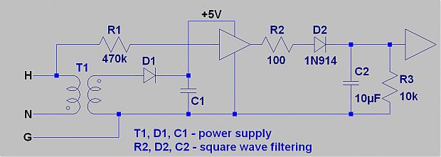
470K half-watt resistor, straight into the input. The ESD diodes will easily absorb the .5 mA peak current.

If it's a micro, you can code out the ripple. If it's a logic gate, hang a diode+RC on the output. If you're running something that needs current like a relay but don't want an IC then PM me. This isn't hard.

EDIT: Make dang sure the resistor is rated for 300V or better, or else use two 220K in series instead.
 
I'd go with the opto. Full wave rectification with a 4-diode bridge, then limit with resistor into optocoupler. Add a cap after the bridge to filter and smooth the current into the opto if you need to keep it up continuously.

Actually, I thought the input to these SSRs was a optically connected to the FET output, so maybe Ohio is right.
 
Yes the SSR is optically isolated but I'm planing to use logic gates to control a 5v ssr as a safety switch between the PID and SSR. Then I will also use the same logic circuit to tell me what is and is not working properly on an annunciator panel.
 
So I've been doing a bunch of googling, and I'm thinking this is pretty close to what you're talking about Ohiobrewingtechnologies:
http://www.arduino.cc/cgi-bin/yabb2/YaBB.pl?num=1235146158/2

Yea one guy said the same thing. Except I'm proposing you don't care about the positive and negative polarities you just have to filter the square wave from the output. There are tons of ways to do it.

470K will not trip a GFCI and the ground leakage it adds is within acceptable limits unless you're talking medical grade.
 
Here, something like this should do it as long as you're using CMOS.
YMMV.

untitled.jpg
 
As far as keeping it simple goes - use the wall transformer, and split the 5V to all your IC's, and wire in an LED at each IC that turns on when it's not safe. This gives you the voltage you need and the indicator you want.
 
Ok redone my design. The controls and logic circuit will all run on 5vdc. I will use a small relay to turn on the pump. I want to use the 5vdc logic to drive a safety relay if you will, to go between my PID 12vdc trigger and the SSR. Would you use an opticalisolator here, a relay, a transister? Part of my problem figuring out what method to use is that I don't know what the current draw is for Auber's 40 amp ssr. So, I can't figure out which components (other than a relay) could handle the current to run the ssr. Any suggestions?
I'm liking the idea of using dc to control tje system. Much easier for me to understand. Smaller cheaper components. And I don't need any rectifiers.
 
Back
Top