List of PJ Electrical Diagrams

Homebrew Talk - Beer, Wine, Mead, & Cider Brewing Discussion Forum

Help Support Homebrew Talk - Beer, Wine, Mead, & Cider Brewing Discussion Forum:

This site may earn a commission from merchant affiliate links, including eBay, Amazon, and others.
50a 5500 2 Element 4 outlet BCS 460
BCS-460-wiring-2-4-c.jpg

Would anyone be able to help me take something like this one (I'll be using a BCS-462), and show me how to add control for 2 (so I can see how multiple are connected) automatic valves from the following link? https://www.oscsys.com/store/product/291 - obviously, I'll be adding a 12VDC power source inside the panel.

Also, won't switching these elements to "manual" effectively just run them at 100%? I guess it wouldn't necessarily be a problem for the BK, but the HLT seems to me like it wouldn't be too useful. Would it be reasonable to throw in 2 PIDS for the manual modes of the HLT and the MLT pump, and a PWM for the BK?
 
Also, won't switching these elements to "manual" effectively just run them at 100%? I guess it wouldn't necessarily be a problem for the BK, but the HLT seems to me like it wouldn't be too useful. Would it be reasonable to throw in 2 PIDS for the manual modes of the HLT and the MLT pump, and a PWM for the BK?

No, not necessarily. Putting a PID into manual mode allows you to select how much heat is being delivered, by percentage. Put it at 100% and the element stays on all the time. Put it at 50% and it's on half the time.
 
No, not necessarily. Putting a PID into manual mode allows you to select how much heat is being delivered, by percentage. Put it at 100% and the element stays on all the time. Put it at 50% and it's on half the time.

I know. But the design uses a BCS without any PIDs, so I'm wondering what the point of manual is UNLESS somebody decides to go to the expense of adding PIDs they likely will never even use anyways. Hence why I asked if doing so would be reasonable...
 
Manual mode is very useful for dialing in the heat to get the desired boil vigor.
 
I know...

If you read the legend on the diagram:

Heating elements:
5000W 240 Volts - HLT & Boil

Additionally - A manual override system is show in case of a controller failure.
The system can be used in manual mode without the controller in place.

The manual mode is there in case of a BCS system failure and is also very useful for initial system start up for heating the strike water while you complete the balance of the BCS setup.

If you do not care to use the manual feature - eliminate the function.

Problem solved.
 
So, I'm looking to put together this guy attached. Really stupid question, where does the temp probe plug in? I see receptacles for the pumps but nothing for the temp probe for the mash tun.

I see the temp goes to 4 & 5 on the PID, is P-J just leaving it up to the user how they want to attach (I'd be looking at XLR)?

Thanks!

image-969144728.jpg
 
heckels said:
So, I'm looking to put together this guy attached. Really stupid question, where does the temp probe plug in? I see receptacles for the pumps but nothing for the temp probe for the mash tun.

I see the temp goes to 4 & 5 on the PID, is P-J just leaving it up to the user how they want to attach (I'd be looking at XLR)?

Thanks!

That's correct, he just shows where the wires go.
 
I am getting ready to do PJs 50a 5500 2 Element 2 outlet 2 PID system, I seen one of your schematics with a timer? do you have a drawing for this??
 
I am getting ready to do PJs 50a 5500 2 Element 2 outlet 2 PID system, I seen one of your schematics with a timer? do you have a drawing for this??
How about some references (links) to the things you are referring to and a little more detail on what you are trying to accomplish. What are you looking for? Help me help you.

P-J
 
I am getting ready to do PJs 50a 5500 2 Element 2 outlet 2 PID system, I seen one of your schematics with a timer? do you have a drawing for this??

How about some references (links) to the things you are referring to and a little more detail on what you are trying to accomplish. What are you looking for? Help me help you.

P-J

What base diagram are you referencing. I can help you but need more info from you. I'm sure that I already have a diagram drawn but need to know the base that you reference.

??????
 
hello P-J,

I am looking to build the following PID system. it's a very simple one and i suspect that you have already made a diagram for it... however i haven't been able to identify it yet.

- single RIMS tube. no HLT to BK controls, i use propane for those.
- 120V heating element (1500 watts)
- single PID
- 2 pumps, with ability to turn them on/off via the panel. pumps run continuously so no need to control them via the PID. on/off indicator lights would be nice.
- EStop

i believe that this diagram is very close: http://www.pjmuth.org/beerstuff/images/Auberin-wiring1-a4-2000w-BIAB-120V-A.jpg

once again: many thanks for your help!

Here is a diagram that I just finished for you as I did not have one that really fit your description. I hope it matches your needs.

And as always - click on the image to see (and save) a full scale diagram printable on Tabloid paper (11" x 17")


I hope this helps you in your adventure.

P-J
 
Here is a diagram that I just finished for you as I did not have one that really fit your description. I hope it matches your needs.

I hope this helps you in your adventure.

P-J
p-j,

i am humbled by your generosity. not only did you design exactly what i had in mind, you threw in several extras (like making sure the element can only fire if the pump is running) that i hadn't thought of.

this is a great design. i'm sure i'll have questions as soon as i get down to building it... in the meantime you have my sincerest thanks.

off to start my adventure!
 
I'm going to give this thread a bump. this does not deserve to be on second page, rather should be in the sticky section.

P-J, you're a hero. Your knowledge is absolutely priceless!

I was wondering if I can run some things by you, P-J, and others on here. I'm slowly putting together a kit to automate my BIAB brewing. My current setup is a 10 gallon pot that sits over two electric stove top elements. I can get 8 gal of wort boiling no problem, but I'm thinking of putting an electric element to control mash temp better and get to boil quicker.

here's what I have so far:

1x 5500w camco element which I'm planning to use with 120v. 1375w should be plenty to maintain mash temp and be safe for 15amp outlet (right?)
1x SYL-2352 PID
1x 40amp SSR
1x K type thermocouple
1x 12v high temp 108gal mini pump which I use to recalculate the wort during mash. (http://www.amazon.com/dp/B007XZAJ3I/?tag=skimlinks_replacement-20)

The whole setup does not have to be anything fancy, no real need for on/off switches other then pump switch(12v), unless there are good (safety) reasons for it. I would like to have an e-stop button tho.

I'm looking for the best way to hook all of this up together.

Thanks in advance!
 
Last edited by a moderator:
...
I was wondering if I can run some things by you, P-J, and others on here.
...
1x 5500w camco element which I'm planning to use with 120v. 1375w should be plenty to maintain mash temp and be safe for 15amp outlet (right?)
1x SYL-2352 PID
1x 40amp SSR
1x K type thermocouple
1x 12v high temp 108gal mini pump which I use to recalculate the wort during mash. (http://www.amazon.com/dp/B007XZAJ3I/?tag=skimlinks_replacement-20)
...
...
The element selection is Ok along with the PID and the SSR. I'd suggest that you choose a Liquid Tight RTD Sensor from Auber Instruments. They are easier to mount and a lot more accurate.

The pump is throwing me a huge curve ball as it is a 12V DC unit. I do not know what the amp draw on it would be so matching a power supply for it becomes an issue. Do you have any idea??? Why not select a 120V AC pump?

I'd be more than pleased to draw up a diagram for you.

Help me help you.

P-J
 
Last edited by a moderator:
you're the best P-J. The pump is a 12v dc. Currently it's running on a 1000mA cell phone charger. This little pump been working great for me, since I'm a BIAB brewer I just want to recirc the wort so 100 gpm is way more than enough for me. I was thinking of just adding an extension cord into the control panel box, attaching the power supply to it and just splice an on/off toggle. No need to overcomplicated anything :) if it makes it easier, we can skip the pump altogether from the wiring.
 
You could just have an outlet like most other setup and just plug the cell phone charger into that. The switch could still be on the panel that way
 
That's a cool find Spellman. It's basically a regular power supply without the plastic casing or wires. Just wire it yourself.

And also you're right. I took a better look at the power supply I'm using, and it is a 2 amp supply. 1amp might not have enough juice to power the pump.
 
I can't take all the credit for the find, there has been a lot of trial and error on this thread: https://www.homebrewtalk.com/f11/cheap-compact-wort-pump-375904/ concerning these pumps, and someone else found it. I don't think these pumps use the whole 2A, but it has been speculated that they run much better with a little head room for power. I plan to build a panel this fall and incorporate 2 of these pumps into it, until I can afford a couple ss chuggers. It looks like this 12v supply will be the easiest way to incorporate them, and maybe just throw a switch on them. I'm guessing I'll need to come back and run my plans by everyone here when it gets closer to that time, as what I'm thinking about doing is slightly different than some of the plans on here. This thread has helped me envision what I can and want to do, so thanks everyone!
 
meshbackhats said:
For the Flash buzzer and the on off switch-

my on off switch for the buzzer does not have the numbers 22 21 12 11, it has 1 2 3 4
just not sure what to wire it to?

Thanks

Has anyone used the auber sw9-110 illuminated maintained switch with the sw2451 pid? I'm having trouble wiring it properly.

PJ Your diagrams are awesome, just finishing my second control panel based on your design. Thank you very much.
 
First, PJ if you are still following this thread, Thank You on my behalf and all others you have helped and made safe through your diagrams.

Through all the information gathered here I have started an electric build.
Most of it is based on the first 30A PID BIAB diagram on page one.
From other information gathered here I have added a timer and 3 way alarm switch for the PID and timer. I believe I've added everything right, but just want to be sure and safe.

If you could find it in your gracious nature to post a diagram (you may have already done one that I haven't found). So that my electrical challenged brain can see it in 11x17 this is how it's correctly done no questions ask wonder. I would be grateful and feel much safer.

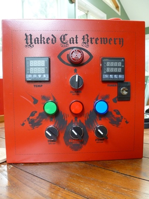
I'm to this stage in the build, but work has slowed me down, so no wiring has been done yet. The E-Stop is mounted on top.

Thank You in advance.

Jeff

P1010907.JPG
 
I am having a hard time sourcing a 240v 30a toggle switch which is part of the parts list on one of the diagrams posted here. Is anyone using one in their build and if so could you please tell me where to get a couple? I have found 240v 10a toggle switch but the diagram shows a 30a switch.

This is the diagram I am trying to follow

http://www.pjmuth.org/beerstuff/images/Auberin-wiring1-a13-SYL-2352-4500w-RIMS.jpg

Thanks for the help
 
Thanks for the reply. I thought about using a standard light switch but since I need 2 switches and my box is a bit smaller I will run out of room. I really don't know much about electrical but the ones I am seeing as far as toggle switches are 240v but only 10A could someone tell me why it must be a 30A switch?
 
There we go thanks for the link. What if I had to step up to a 2000w or 3000w heating element would that switch still work you think?
 
I am having a hard time sourcing a 240v 30a toggle switch which is part of the parts list on one of the diagrams posted here. Is anyone using one in their build and if so could you please tell me where to get a couple? I have found 240v 10a toggle switch but the diagram shows a 30a switch.

This is the diagram I am trying to follow

http://www.pjmuth.org/beerstuff/images/Auberin-wiring1-a13-SYL-2352-4500w-RIMS.jpg

Thanks for the help
http://www.digikey.com/product-detail/en/S821/360-2096-ND/1007153
Digikey changed the part numbers on their site. The linked switch is rated for 30A @ 250V when used with resistive loads like the heating element application that we use.

Here is the PDF file with the details of that switch series. http://www.nkkswitches.com/pdf/stoggleshighcap.pdf

I hope this helps you.

P-J
 
I see. I guess I need to slow down and do a little more reading before I jump to asking questions. Thanks again for all your help and without your wiring diagram I found I would be at a total loss.
 
I see. I guess I need to slow down and do a little more reading before I jump to asking questions. Thanks again for all your help and without your wiring diagram I found I would be at a total loss.

Emphasis >
...reading before I jump to asking questions.
That is NEVER a problem. If we cannot talk back and forth we are all in deep trouble. Actually you helped me with the discovery that the vendor changed his product name/link.

Also, the PDF file can be a little difficult to interpret completely.

I'm just very glad that I am able to help you. Wishing you the very best.

P-J
 
Back
Top