Let's share rtd amplifier circuits?

Homebrew Talk - Beer, Wine, Mead, & Cider Brewing Discussion Forum

Help Support Homebrew Talk - Beer, Wine, Mead, & Cider Brewing Discussion Forum:

This site may earn a commission from merchant affiliate links, including eBay, Amazon, and others.

Ramdough

Well-Known Member
Joined
Aug 28, 2012
Messages
189
Reaction score
6
Location
Austin
Ok, so I have done a searches on the internet for rtd circuits. I plan to interface to an arduino. I have had various successes in my search but nothing that I did not have to modify.

So, let's compile a thread with rtd circuits that have been tested and used for brewing.


Sent from my iPhone using Home Brew
 
With an Arduino I'd rather use digital temperature sensor DS18B20 . It's precalibrated, sends data in a digital format, requires only one digital pin, and you can wire a bunch of sensors to the same pin.
 
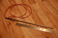
Might I also suggest NTC thermistors: cheap, accurate for small temperature ranges and small. The latter makes it easy to incorporate them into many things, like the probe I made below. Its just a bit of 6mm OD stainless tube closed off at one end with the thermistor stuffed down in it. Add a bit of shrink wrap and the total cost was about £3. The stainless bulkhead fitting near the end of it cost more than the probe itself was to make!


RTD's are over hyped for homebrewing, I guess it's just convenient that they are the only type of probe easily got already in probe form.

EDIT: I also made a PIC device to read this - I could post the basics of it if it would be of use, it's just a simple voltage divider though.
 
With an Arduino I'd rather use digital temperature sensor DS18B20 . It's precalibrated, sends data in a digital format, requires only one digital pin, and you can wire a bunch of sensors to the same pin.

And they are incredibly accurate and respond quickly. Definitely the easiest temp. sensor to integrate with an arduino. NTC Thermistors are not linear and require some math determine the temp (Remember quadratic equations??). I haven't tried an RTD circuit yet, but I think a fixed gain Op Amp circuit would work ok, or maybe just a resistor network.

Here is a non-inverting fixed gain op-amp circuit.
300px-Op-Amp_Non-Inverting_Amplifier.svg.png
 
The most accurate way to read an RTD is to tie them to a high-tolerance resistor, drive a well-regulated current through them, then measure the voltage drop with an A/D. I've used an
AD7783 to do this since it has an internal current source. It also has a reference channel that allows you to cancel out any inaccuracy in the current source. Great part. I actually used this part and a bunch of analog switches (ADG711) to read 8 RTDs with very tight accuracy.

http://www.analog.com/static/imported-files/data_sheets/AD7783.pdf

Here's a great explanation for using this chip. Might be more than most here are interested in.
http://electronicdesign.com/test-am...s-can-multiplex-accurately-measurement-system

If anyone really wants to pursue this, PM me and I'll send you a schematic for this.
 
Back
Top