Keg to ekeggle conversion pics

Homebrew Talk - Beer, Wine, Mead, & Cider Brewing Discussion Forum

Help Support Homebrew Talk - Beer, Wine, Mead, & Cider Brewing Discussion Forum:

This site may earn a commission from merchant affiliate links, including eBay, Amazon, and others.
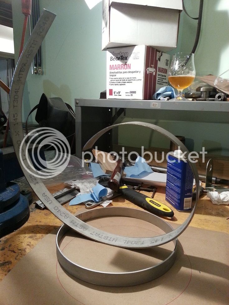
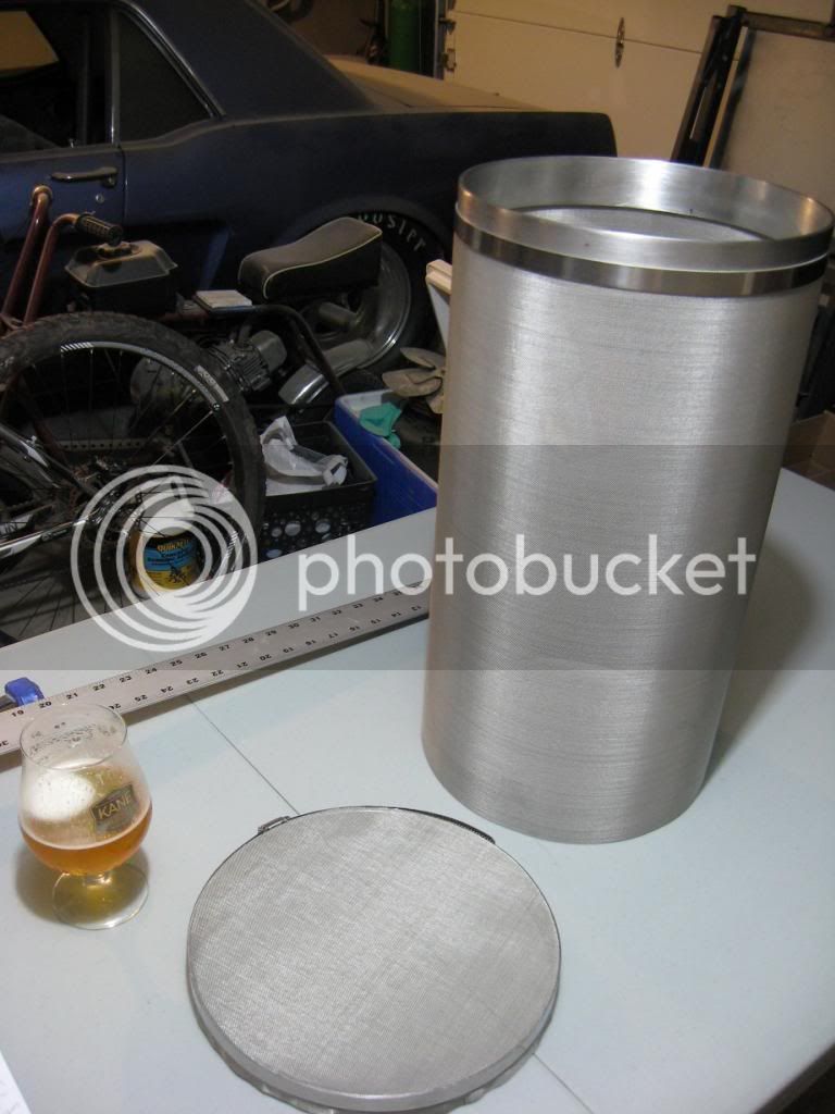
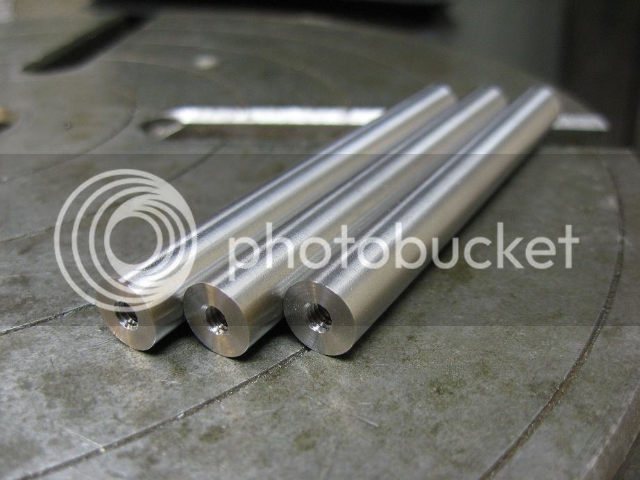
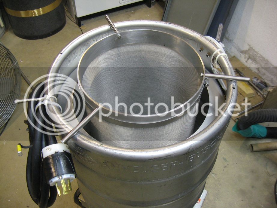
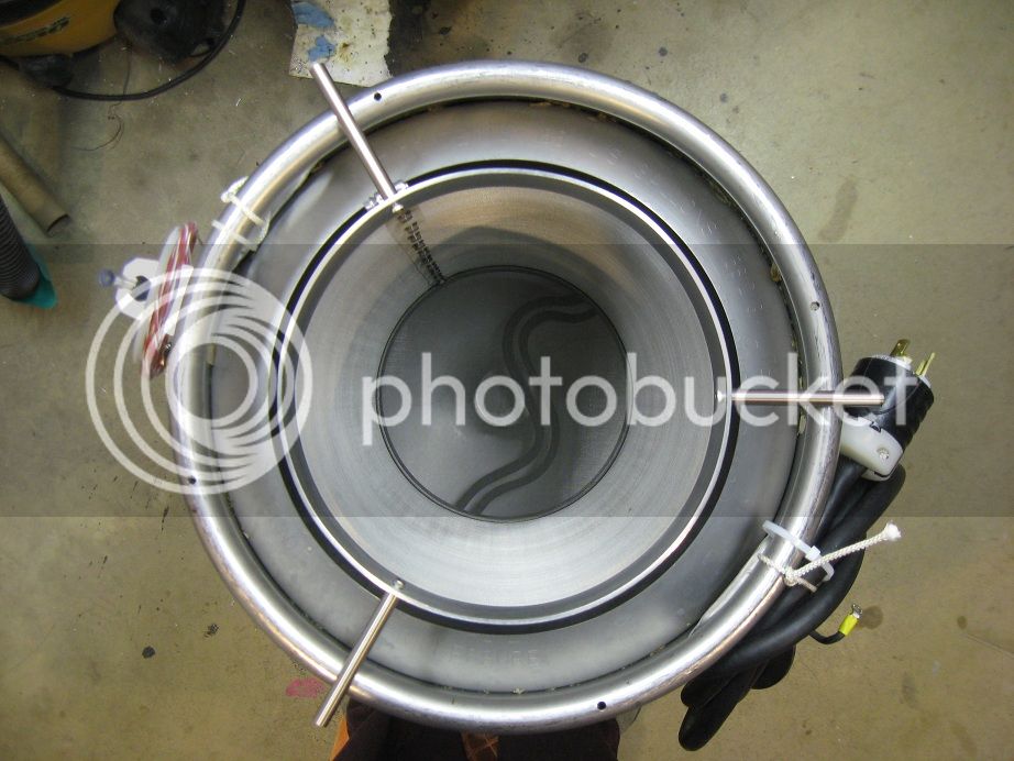
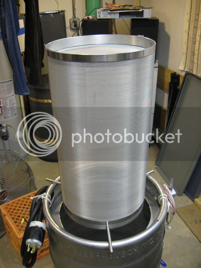
I'm building a 10"x19" hop spider to use for a few batches in my current BK which is a keggle (the one in all of the previous photos). I'm about to convert to a HERMS system, so the keggle will become a HLT. If the hop spider works well in my keggle, I'm going to build a bigger version (12"x19") for the new BK. It seems like a lot of work for one or two batches before the HERMS system is ready, but I want to prove that the design works before I build the final version for the new BK.

20130512_212435s_zps7a502a16.jpg


IMG_5994s_zps7e18634c.jpg
 
These are the arms for the hop spider. They're 3/8" diameter stainless, 3.5" long with 8-32 threads. I decided to bolt them (instead of welding) to the hop spider's top ring to make future modifications easier.

IMG_5996s_zpsf712ceed.jpg
 
Here's the completed hop spider. The bottom ring is 3/16" above the element, so I hope that means there will be a lot of hop movement in the basket! The bottom ring, because it hangs down, should act as a shroud or guide for the boil. I want that energy to go into the basket instead of around and up the outside of it. If it doesn't work out as planned, I can add a longer shroud that will hang down past the element.

IMG_6017s_zps64a01f71.jpg


IMG_6022s_zps81789df8.jpg


IMG_6023s_zps6df661c4.jpg


IMG_6018s_zps963a3546.jpg
 
Thanks, Tiber Brew. I already had some terminal strips, so I just used them. The next version will definitely have something like you used.

The control panel is done except for one minor addition. Testing will be soon!

IMG_5436scropped.jpg


IMG_5439s.jpg

I love the toolbox controller, I am thinking of doing the same thing, did you flip over the shelf piece so it is upside down? Also are your terminal strips and contactor just fastened to the bottom of the toolbox or did you use some kind of false bottom/board? And the Ssr etc just on the backside of the toolbox? Thanks!
 
I love the toolbox controller, I am thinking of doing the same thing, did you flip over the shelf piece so it is upside down? Also are your terminal strips and contactor just fastened to the bottom of the toolbox or did you use some kind of false bottom/board? And the Ssr etc just on the backside of the toolbox? Thanks!

I cut out most of the top shelf of the tool box. The 1/2" - 3/4" lips at the front and rear of the toolbox are all that's left of it (you can see the rear lip under the PID and between the two hinges in the picture you quoted). I then made a hinged shelf that flips up and down. When it's flipped down, it lays on those two lips. The PID and switches are mounted to the hinged shelf for easy access to the wiring.

There is no false bottom. All of the components are mounted directly to the bottom of the box. Rubber feet elevate the box so the screw heads don't touch whatever surface you place the control box on. The SSR and all of the other stuff is mounted to the rear of the box. I made a ~4" circular hole in the rear panel. The heatsink bolts to the rear panel and covers the hole. This enables the SSR to be bolted directly to the heatsink from inside the box for good heat transfer.

20130528_195802s_zpsf9444615.jpg


20130528_195542s_zps14bbafc5.jpg


20130528_200110s_zps7cd2efd6.jpg
 
Excellent, thanks so much, those were the ideas I was thinking too, hinges and rubber feet so the toolbox isn't sitting on the screws. I have been looking at all kinds of control box options, but the toolbox with the ability to close over the switches and the pid is the winner in my head, thanks for confirming it with your awesome build!
 
Do you think it's necessary to mount the heat sink outside the toolbox? I was looking at mounting it inside cause there would be affair amount of air space, but there is no circulation and I'm not sure exactly how hot the Ssr and heat sink will get. I am also looking at, if being inside the toolbox is too hot for it, mounting it under the lid so hidden when closed but when the toolbox's lid is open it is free to the air, would it get too hot to the touch if its next to the switches and pid if it was bumped by a hand when flicking switches etc? Sorry to hijack your thread but your ideas are the same as floating around my head, thanks!
 
Do you think it's necessary to mount the heat sink outside the toolbox? I was looking at mounting it inside cause there would be affair amount of air space, but there is no circulation and I'm not sure exactly how hot the Ssr and heat sink will get. I am also looking at, if being inside the toolbox is too hot for it, mounting it under the lid so hidden when closed but when the toolbox's lid is open it is free to the air, would it get too hot to the touch if its next to the switches and pid if it was bumped by a hand when flicking switches etc? Sorry to hijack your thread but your ideas are the same as floating around my head, thanks!

Funny you should ask. I brewed 4 days ago and the temperature outside was 86F. I taped a thermometer onto one of the heatsink fins. It was pretty hot to the touch, but not so hot that I couldn't hold my hand on it for a while.

I don't think it's a good idea to mount the heatsink inside an enclosure without ventilation, though. Mounting it outside is pretty simple and costs nothing. I feel like I've read threads on this subject. If I come across one I'll let you know!

20130602_134859_resized_zpsace17c3f.jpg
 
I can't seem to get my element to seal very well, anyone have some recommendations?
 
I can't seem to get my element to seal very well, anyone have some recommendations?

More info? leaking at threads? That may be because you may be putting a 1"NPS element into a 1" NPT(tapered) fitting..

If so:

Best answer, weld on a 1.5" or 2" ferrule and use an element adapter that has 1" straight thread

Good answer - tap out the 1'" NPS to NPT with a straight tap (and lots of leverage and lube..)

Not as good answer - run a tapered tap in from both sides until the element seals on the gasket and not the threads.

cheap answer - use teflon tape...

I'm using a weldless setup - I was playing around and couldn't get it to seal properly.

Element -> Washer -> Keg Wall -> O-ring -> Nut

I also tried:

Element -> Washer -> O-ring -> Keg Wall -> Nut

That didn't work as well.
 
I'll try that again but I found the wall was too thick and I couldn't get the nut to grab. I'll give that another go. Thanks!

Try flipping the lock nut over. The shoulders are rounded on one side and might allow you to grip the element threads.
 
I made a little progress on the HERMS conversion this weekend. I made a coil out of 50', 1/2" X .020" wall SS tubing and mounted it in the old keggle. Before coiling, I attached compression fittings and ball valves to each end of the tubing. The tubing was filled with water and coiled around a sixtel. No kinks! Everything else was pretty straightforward with the exception of turning the coil's 90 degree compression fittings into 77 degree compression fittings. This made the male NPT threads of the compression fittings perpendicular to the tangent of the coil and keg. Before cutting the fittings apart, I enlarged the passages from 0.368" to 0.453" to match the inside diameter of the coil and increase flow (I may whirlpool and chill through the HERMS coil). The BK goes under the knife next!

20130928_181954_zps5a060ce8.jpg


20130928_170249_zps5d168296.jpg


20130928_191543_zpscfc68cee.jpg


343ca190-6fe7-499d-8563-7e54b2d5befd_zps622b05e0.jpg
 
Thanks! I tested flow through the coil today with cold water, a Little Giant 3-md-hc pump, and 3/8" id silicone tubing and saw 2.6 gpm. Hopefully it's enough for a good whirlpool. What flow rates have you seen with shorter coils?
 
I had 5/8" x 25' copper in a keg for a 30 gallon mash, and it was a bit slow... so kinda apples to oranges... maybe port&polish the inside of your fittings and keep the elbows to a minimum... worst case is you can't do fast ramp up to mash out, but I am sure it will hold and ramp decently...
 
I don't think I'll ever have to recirculate mash at 2.5 gpm for 10 gallon batches, so I should be OK!

I just finished my HERMS coil support. It's made of 1/16" SS rod that wraps around the coil. It looks like a long, skinny oval and is welded together on the outside of the coil (but not to the coil). From there, it makes a straight shot to the top rim of the keg where it's fastened with an 8-32 SS bolt. The support prevents the back side of the coil from sagging which has three benefits- It eliminates twisting of the HERMS tube at the compression fittings and keeps the coil perfectly level at all times to aid draining. It also adds a lot of strength to the assembly. Before adding it, I found that setting the HLT down on the ground or a table was enough to jar the coil and cause it to sag slightly. Overkill, maybe, but if it prevents leaks at the compression fittings, helps draining, and makes me not have to think about being super careful when moving the HLT, I'm all for it!

20131004_225946_zpsf636f4b1.jpg


You did a great job coiling that tubing! Why did you decide to support it with a rod from the top instead of a some kind of foot on the bottom?
 
Thank you! Your setup is looking great, too! The coiling was not easy. The trick was filling the tubing completely with water and coiling it around a totally stationary object and not letting any part of the tubing move away from the thing you're coiling it around. See pic below.

I didn't go to the bottom with the support because the bottom of the keg is sloped toward the center. Any downward force would cause the foot to slide toward the center of the keg and cause the coil to drop which is exactly what I'm trying to prevent! A bolt would cure that, but I don't like the idea of a bolt below the liquid level. The bottom foot migrating toward the center of the keg would also present a twisting force to the coil if I attached the foot to more than one coil. If the HLT bottom was flat, I definitely would have supported it from the bottom. It would have been much easier and quicker to fab. Going to the top is also stronger than going to the bottom if the support rods are the same diameter. Imagine holding a thin metal rod between your hands. If you were to push it together you could probably make it bend and your hands would move toward each other. Now imagine trying to stretch it by moving your hands away from each other. Your hands are not going to move! I think the thin, top mounted support is the most elegant solution in this case.

20130925_211526_zps3d879082.jpg
 
yeah, 2.5G/m is 4 minute turnover for a 10 gallon batch, maybe a bit slower for first runnings.. we were trying to do 30+ gallons.. If you find you need more, you may want to try separating the tube coils by one twist of wire each to lower boundary area, but guessing it would only get you a few percent increase.. your design is simple and elegant.. very nice.
 
I just mounted the sight glass to the new BK. It's a 1/2" x 3/16" polycarbonate tube. I used a 3/8 OD x 1/8" ID tube on my old BK and am not thrilled with it, so I decided to try a bigger size for this one. The top compression fitting now has a 1/2" barb fitting screwed into it so I can easily recirc PBW through it during cleaning.

20131006_154520_zpsf493eeba.jpg


20131006_154436_zpsef5b1473.jpg
 
Thanks, Lorglath!

Here's the BK's tangential inlet ready to be welded to the vessel. It's a 6" long 1/2" npt nipple with one end cut off. I turned it down to clean it up a little and welded a 1/2" nps lock nut to it so it can be held from twisting when installing a ball valve. The kettle wall is thin, so I figured holding the inlet still is mandatory!


20131021_215619_zps6d7527d2.jpg
 
OK I'll bite.

I totally get the angle cut so it will point the ball valve at an angle and I agree with the nut to hold it during tightening but...

Where are you installing this?
 
Yep, it's a whirlpool inlet. Here's the completed kettle. It's a 25 gallon Concord pot. The element is tri clamp removable and mounts in a 3" ferrule. I have a "bazooka" tube that attaches to the dip tube that I'm going to experiment with. It will be used in conjunction with a large SS hop basket that I have yet to make. The hop basket will be similar to the one I made for my keggle shown earlier, just a larger diameter and a little shorter.

20131029_131042s_zps652f4ddd.jpg


20131103_144714s_zps8f3296e2.jpg
 
This has to be my favorite part of the new system- a tri clamp removable element and element enclosure. This makes clean up so easy. Not only does it let you clean the element easily, but it gets the cord out of the way when you're tossing the BK around.

I'm debating making the HLT's element tri clamp removable, but cleaning that shouldn't be an issue as it will only touch water.

IMG_9209s_zps050f3f31.jpg


IMG_9197s_zpsb779ecbb.jpg


IMG_9200s_zpsa13e3595.jpg
 
Thanks, Vadim!

I would rather have a little more room than just enough. My element passes through the enclosure unlike some other designs I have seen that use three tri clamps or some kind of box that covers the electrical connections. With those types, you can get away with smaller ferrules. Besides the ferrule on the BK and the end cap with the strain relief, the whole assembly is just one piece. In order to have plenty of room for the ground lug and wiring, I needed an enclosure of this length. With this length enclosure, a smaller diameter would not be possible. I actually had to ever so slightly straighten the bends of my ripple element just to get it through the enclosure. It is so slight that you can't even tell it has been straightened, but it was completely necessary to get it through the enclosure. Maybe I could have used a 2" or a 2.5" ferrule, but that would have required a shorter enclosure. Here's a pic of just the enclosure to give you a better idea of how it's constructed:

20131003_193230s_zps521623f8.jpg


And this pic shows the slightly straightened element:

20131103_144714s_zps8f3296e2.jpg
 
Your quality design work and craftsmanship, not to mention your considerable photo layout talent leaves me speechless... and bit envious.

You sir, have my respect and admiration.
 
Just one question. . . All the shiny parts and hard work yet you're choosing to use hose barbs over quick connects or camlocks. How come?
 

Latest posts

Back
Top