No sir, that is the wrong type of interface. That's called I2C and is not how this is implemented.Got My pi fermention working by puré luck and use of this forum.
Now ofcourse i want à lcd.
But realise that i Will nerver be able to build one.
Is it possible to use this https://www.ebay.com/itm/121099129816
You are using an out of date browser. It may not display this or other websites correctly.
You should upgrade or use an alternative browser.
You should upgrade or use an alternative browser.
How To: BrewPi LCD Add-On
- Thread starter day_trippr
- Start date

Help Support Homebrew Talk - Beer, Wine, Mead, & Cider Brewing Discussion Forum:
This site may earn a commission from merchant affiliate
links, including eBay, Amazon, and others.
OP
OP
[...]Is it possible to use this https://www.ebay.com/itm/121099129816
Well...yes, you can.
But as that LCD uses an I2C interface it requires hacked BrewPi firmware for the Arduino, as the "stock" method of interfacing the 4x20 LCD is via a 4-bit parallel bus.
[btw, the I2C version is typically the same parallel display with an "I2C Backpack" attached to do the conversion from I2C to 4-bit parallel.]
If you go here you'll find a discussion and "How To" to use an I2C display with BrewPi. You'll have to follow the sub-thread to find an example/hacked hex file, or perhaps contact one of the participants to get a copy...
Cheers!
I need to apply that which I use at work: "Never say "no," give the conditions under which you can say "yes."Well...yes, you can.
wbarber69
Well-Known Member
- Joined
- Oct 13, 2013
- Messages
- 2,191
- Reaction score
- 263
He's saying yes because there are hundreds of brewpi implementations that use I2c in this thread. there is actually code to support it built right in. Involving just a few changes to the source code. it was never implemented or supported fully by the brewpi guys so you are on your own when it comes down to it.
So you dont have a have to change the brew PCB? Can you show a picture of your change to the design of your actual brewpi device?
One comment says a common issue is the 595 being incorrectly wired
http://hackaday.com/2014/02/27/fail-of-the-week-reset-issues-with-595-and-hd44780/#comment-1233030
If you don't have that issue then another says power cycle the lcd periodically as the firmware has a bug that causes it to get out of sync. I have experienced the bug over I2c myself.
http://hackaday.com/2014/02/27/fail-of-the-week-reset-issues-with-595-and-hd44780/#comment-1816924
I don't have a schematic for the design but use a 2n2222 with emitter to uno ground and collector to lcd ground. then use a 1k resistor betweeen a digital output pin and base.
I cannot show you a picture as I do not have a brewpi device, just a little experience with running an i2c lcd display with an uno. I don't wish to say any more as I seem to be misleading you in appearing to have experienced in solving the issue. While I have encountered the issue of the lcd scrambling, I have not tried to fix it as in my case a few power cycles by hand worked for me.
wbarber69
Well-Known Member
- Joined
- Oct 13, 2013
- Messages
- 2,191
- Reaction score
- 263
Forget the fact that the op is a hardcore ole-school EE with more knowledge on the subject than anyone else on hbt and even he gets stumped by this issue. personally I think it's a problem with the manufacturing process of the screens themselves.
I'm not going to assume I know more than those who have been helping here. I did find a page about the relays which discusses something I have not seen covered here: How to wire the relays so that it fully takes advantage of the opto-isolators.

https://arduino-info.wikispaces.com/RelayIsolation
Seems like someone having an issue with noise might be able to isolate things further by following the tips in that article.
If I understand that article correctly, the way to do it would be to remove the jumper, and separately power and ground the relay via the JD-VCC and ground pins there?
Seems like it would also cut down on the amperage needed from the Arduino itself since the coil power would now be separate.
I started building this. Not all the parts have arrived yet, but I got itchy feet.
I know the 10k trim pots have arrived but they are not in my box of tricks. I know I showed my son who looked at me like "nerd!" Then I put them away.
The IC holders and rotary encoders arrived today. I found them outside amongst shredded packaging, the dog got to them. She's in the tearing everything chewable up phase, including postage packaging. Hopefully the rotary encoders are not damaged.
View attachment 1472043251022.jpg
View attachment 1472043286798.jpg
I can only think that the 10k trim pots got put back into their packaging and this "empty" packaging accidentally got thrown out.
Ordered more on ebay. I guess since I am still waiting on parts, it doesn't matter and it is only $2, but thats not the point. I got into soldering mode, now I am forced to stop!
Ordered more on ebay. I guess since I am still waiting on parts, it doesn't matter and it is only $2, but thats not the point. I got into soldering mode, now I am forced to stop!
I need to make mine as well. I have a stack of boards too ... will offer a few on here when I have time to actually send them out to folks.
I have a proposition for someone who is a skilled assembler/solderer. If you have been kicking around the idea of getting some boards but didn't want to wait, didn't know where to get them, didn't want to pay for 10 at a time, or maybe you just really like electronic assembly, this may be interesting for you.
I have 12 boards and parts for two. I have 0 time to get these done and a decided lack of sharp eyesight and steady hands these days so I am somewhat leery of soldering the SMD (even though there's only one per.) I send you 12 boards plus parts for two, you send me back two assembled board and keep 10 bare ones.
I would of course pay for postage both ways, I'd send the parts with a label to return the boards to me when done. Since shipping is somewhat prohibitive, this should be limited to US folks.
I have a proposition for someone who is a skilled assembler/solderer. If you have been kicking around the idea of getting some boards but didn't want to wait, didn't know where to get them, didn't want to pay for 10 at a time, or maybe you just really like electronic assembly, this may be interesting for you.
I have 12 boards and parts for two. I have 0 time to get these done and a decided lack of sharp eyesight and steady hands these days so I am somewhat leery of soldering the SMD (even though there's only one per.) I send you 12 boards plus parts for two, you send me back two assembled board and keep 10 bare ones.
I would of course pay for postage both ways, I'd send the parts with a label to return the boards to me when done. Since shipping is somewhat prohibitive, this should be limited to US folks.
I can do it for you. P.M. me if the offer is still out there.
ksga
Member
- Joined
- Apr 18, 2016
- Messages
- 10
- Reaction score
- 0
Maybe my search skills are somewhat faulty, but I couldn't find a solution to the garbled display error that I, and as far as I can see, others are experiencing.
I was googling a bit for it, and as far as I can tell it's related to the sainsmart or similar octocoupler relays. People using SSR's are reporting that the issue doesn't exist.
I would argue that this is the case. The issue is not the actual switching of the relay, but noise being fed back from the AC side. I made some tests, plugging and unplugging a lamp from the socket while the relay was on, and without fail it causes the lcd to garble...
On https://arduino-info.wikispaces.com/RelayIsolation a proposed solution would be to power the relays through the alternate power connection, and not grounding it to anything touching the arduino/shift register/lcd. EDIT - looks like LBussy found it already
That would be nice, however I do not have the room for a separate ac-dc in my enclosure so I'm looking for a solution to isolate the two circuits from any ripple or noise.
Since I'm a complete NOOB when it comes to electronics I'm crasping in the blind for a solution.
Would this maybe add any kind of isolation?? Or maybe just cause everything to fry
The plan is to add a nice big capacitor right after the dc-supply and a diode on the supply to the relays.
OP
OP
Elco had a 10uF can-style electrolytic soldered directly to the LCD on one of his designs - I think it was Rev C but not sure.
Don't know if it was effective. My guess is it wasn't.
Given someone has a model that fails easily, it would be interesting to wire up a totally separate 5VDC power supply (got an orphaned 5V cell phone charger?) that only drives the separate relay coil power input (I'm assuming everyone's using the 2-channel relay module with a JVCC jumper) and gets its AC input from somewhere other than the source that runs everything else.
You've have to common the DC ground with the rest of the build so it's properly referenced, of course...
Cheers! ("For SCIENCE!")
Don't know if it was effective. My guess is it wasn't.
Given someone has a model that fails easily, it would be interesting to wire up a totally separate 5VDC power supply (got an orphaned 5V cell phone charger?) that only drives the separate relay coil power input (I'm assuming everyone's using the 2-channel relay module with a JVCC jumper) and gets its AC input from somewhere other than the source that runs everything else.
You've have to common the DC ground with the rest of the build so it's properly referenced, of course...
Cheers! ("For SCIENCE!"
)I have a proposition for someone who is a skilled assembler/solderer. If you have been kicking around the idea of getting some boards but didn't want to wait, didn't know where to get them, didn't want to pay for 10 at a time, or maybe you just really like electronic assembly, this may be interesting for you.
I have 12 boards and parts for two. I have 0 time to get these done and a decided lack of sharp eyesight and steady hands these days so I am somewhat leery of soldering the SMD (even though there's only one per.) I send you 12 boards plus parts for two, you send me back two assembled board and keep 10 bare ones.
I would of course pay for postage both ways, I'd send the parts with a label to return the boards to me when done. Since shipping is somewhat prohibitive, this should be limited to US folks.
Would be happy to provide a 2nd source of labor, if needed.
They are being done @stlbeer but thanks for the offer!Would be happy to provide a 2nd source of labor, if needed.
ksga
Member
- Joined
- Apr 18, 2016
- Messages
- 10
- Reaction score
- 0
Elco had a 10uF can-style electrolytic soldered directly to the LCD on one of his designs - I think it was Rev C but not sure.
Don't know if it was effective. My guess is it wasn't.
Given someone has a model that fails easily, it would be interesting to wire up a totally separate 5VDC power supply (got an orphaned 5V cell phone charger?) that only drives the separate relay coil power input (I'm assuming everyone's using the 2-channel relay module with a JVCC jumper) and gets its AC input from somewhere other than the source that runs everything else.
You've have to common the DC ground with the rest of the build so it's properly referenced, of course...
Cheers! ("For SCIENCE!"
Running out of patience on this one....
I decided that I did have room for another 5V DC supply in my enclosure and scrapped another cell phone charger. (They are still running on the same AC-supply since I don't have two independent power supplies to my house or a generator lying around - actually there is a 80KVA generator standing right next to where I live, but it seems a bit excessive running it just to power a 200mA relay
)I must say I disagree on grounding the arduino side of the relay since the ground is connected to the other side of the octo-coupler, and I feel it would defeat the purpose of isolation (but tried with and without doing it anyways...)
I've done just about everything I could think of, simultaneously and separately.
Added a capacitor right at the display pin 1 and 2
Added a capacitor across the shift register supply and GND
Added a capacitor at the relay JD-VCC and GND
Added a capacitor right at the output from the DC supply
Used twisted pair wiring connected only to ground for the VCC and inputs on the relay
Removed the load and ran an unconnected test (set fridge to 30C and waited for the heat cycle to start and then warmed the sensor until reaching the set point)
The conclusion is - garbled display happens after a seemingly random period of time/relay clicks!!!
Now I'm waiting for a couple of SSR's to arrive, and will use them for the twin setup.
OP
OP
If you didn't tied the ground lead from your added power supply to the system ground the added supply output would float...
cheers!
cheers!
ksga
Member
- Joined
- Apr 18, 2016
- Messages
- 10
- Reaction score
- 0
If you didn't tied the ground lead from your added power supply to the system ground the added supply output would float...
cheers!
Probably true (again, I have to stress that I know absolutely NOTHING about electronics or electricity, but ask me about statical loads or timber joints
)but the result is the same regardless....
Would someone please have pity on a poor soul and answer a couple questions that are already answered in here somewhere?
Thanks in advance.
- When using the shield, do the pins line up straight across on the LCD (I hope)?
- What's the connections for the encoder?
Thanks in advance.
OP
OP
Gonna have to ask: hand-built shield, or one of Cadibrewer's PCBs?
If the former, no way - it wasn't a priority
If the latter, yes, the headers are sequential, but be aware that the silkscreened labels are flopped end-for-end.
The encoder switch uses the through-headers from the Uno.
The pushbutton uses IO 7, the two encoder signals use IO 8 & 9 (switch them if the values decrement when rotating clockwise) and use any GND pin available for the last wire...
Cheers!
Bigdaddyale
Well-Known Member
The DirtyCheap red shields are labeled 1-16 with #1 on the left and #16 on the right next to the trimmer. The one Cadibrewer sent to Day_ Tripper ( the purple one) was labeled backwards.Gonna have to ask: hand-built shield, or one of Cadibrewer's PCBs?
If the former, no way - it wasn't a priority
If the latter, yes, the headers are sequential, but be aware that the silkscreened labels are flopped end-for-end.
The encoder switch uses the through-headers from the Uno.
The pushbutton uses IO 7, the two encoder signals use IO 8 & 9 (switch them if the values decrement when rotating clockwise) and use any GND pin available for the last wire...
Cheers!
Cadibrewer's.Gonna have to ask: hand-built shield, or one of Cadibrewer's PCBs?
Aha ... that was the comment I found about using long male headers. I have female headers in mine. Live and learn.The encoder switch uses the through-headers from the Uno.
The pushbutton uses IO 7, the two encoder signals use IO 8 & 9 (switch them if the values decrement when rotating clockwise) and use any GND pin available for the last wire...
Gotcha!The DirtyCheap red shields are labeled 1-16 with #1 on the left and #16 on the right next to the trimmer. The one Cadibrewer sent to Day_ Tripper ( the purple one) was labeled backwards.
Thank you both!
Finished ... need to put it in a box now of course.
Thanks to @day_trippr for answering stupid questions, @cadibrewer for doing the boards, and @gromitdj for saving me from having to solder that mosfet.

Thanks to @day_trippr for answering stupid questions, @cadibrewer for doing the boards, and @gromitdj for saving me from having to solder that mosfet.
Last edited:
Thanks to @day_trippr for answering stupid questions, @cadibrewer for doing the boards, and @gromitdj for saving me from having to solder that mosfet.
Glad to see it worked out for you! Now that I know you were successful, I guess I've got to get to work on mine. Thanks again!
CadiBrewer
Well-Known Member
Finished ... need to put it in a box now of course.
Thanks to @day_trippr for answering stupid questions, @cadibrewer for doing the boards, and @gromitdj for saving me from having to solder that mosfet.
I have three spare bare shield boards available, first come first served. I have about $2 each in them including shipping to me, so I'll let them go for that plus actual postage vial PP. PM if interested.
No problem at all! Glad it fired up for you.
Which rotary encoder did you use? I like that one with the board attached. Where'd you find it?
@gromitdj sent the encoder board along when he sent my shields back. I guess he had them made somewhere. The encoder is the one in the original Mouser BOM that someone posted.Which rotary encoder did you use? I like that one with the board attached. Where'd you find it?
@CadiBrewer,
If it will work with your rotary encoder, PM me your address and I'll send you a couple of the Breakout Boards. I just used a Male breakaway header with it.
I had the boards made and then ordered the wrong rotary encoder, so they aren't doing me much good.
If it will work with your rotary encoder, PM me your address and I'll send you a couple of the Breakout Boards. I just used a Male breakaway header with it.
I had the boards made and then ordered the wrong rotary encoder, so they aren't doing me much good.
CadiBrewer
Well-Known Member
@CadiBrewer,
If it will work with your rotary encoder, PM me your address and I'll send you a couple of the Breakout Boards. I just used a Male breakaway header with it.
I had the boards made and then ordered the wrong rotary encoder, so they aren't doing me much good.
PM sent. Thanks a ton!
Has anyone tried one of these to help with scrambling?
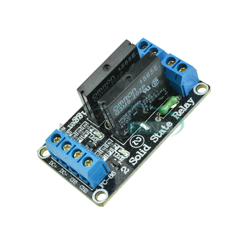
https://www.aliexpress.com/item/5V-...-High-Level-fuse-for-arduino/32417717089.html
https://www.aliexpress.com/item/5V-...-High-Level-fuse-for-arduino/32417717089.html
Has anyone tried one of these to help with scrambling?
https://www.aliexpress.com/item/5V-...-High-Level-fuse-for-arduino/32417717089.html
Looks to me like the load is only 2amps. I don't think that helps with A/C or refrigerator load requirements.
Crap I missed that part. Never mind.Looks to me like the load is only 2amps. I don't think that helps with A/C or refrigerator load requirements.
OP
OP
To answer the "SSR" question generically, yes, from what I've read they seem to be a cure for those plagued by scrambling LCDs...
Cheers!
Cheers!
Made progress with a DIY shield. Probes work and it switches hot and cold relays.
I'll have to duck out and get some female-female dupont wires and test out the screen.
View attachment 1475549602939.jpg
I'll have to duck out and get some female-female dupont wires and test out the screen.
View attachment 1475549602939.jpg
OP
OP
Excellent work to get that far 
And you're running it over wifi as well? Extra credit
Cheers!
And you're running it over wifi as well? Extra credit
Cheers!
Excellent work to get that far
And you're running it over wifi as well? Extra credit
Cheers!
I hadn't quite cut the etch to the onboard LED properly (this shield had the components pre-soldered). Had to "guess" which were the corresponding lines to cut too!!
It's now working properly.
Pulled apart a wall wart to have a look at how I might mount it in the project box to power the arduino.
OP
OP
I'm fortunately to have an old-school e-hobby store a half hour away, and they carry pretty near every imaginable diameter of shrink wrap tubing.
I picked up a chunk that was wide enough to insert the guts of a $2 eBay 9V 1A wart, shrunk it snug, and hard-wired it inside my wee minion case.
The volumetric difference is dramatic - I literally could not have added the LCDs to my minions if I kept the wall wart cases intact.
You could use electrical tape as well - it's not like there's a lot of heat going on inside one of these things, so it should stay wrapped...
Cheers!
Similar threads
- Replies
- 9
- Views
- 2K
- Replies
- 11
- Views
- 1K

Latest posts
-
 Wanted Wanted to buy - Used cask (pin)
- Latest: IslandLizard
-
-

-

-

-

-