How To: BrewPi LCD Add-On

Homebrew Talk - Beer, Wine, Mead, & Cider Brewing Discussion Forum

Help Support Homebrew Talk - Beer, Wine, Mead, & Cider Brewing Discussion Forum:

This site may earn a commission from merchant affiliate links, including eBay, Amazon, and others.
Ok, so the Uno is making its own 5V. That's good - powering the Uno from the RPI via the USB connection can range from "ok" to "iffy at best" depending on the cable used. The experiments I did - all with 18" or shorter USB cables - had a worst-case under 4.3 volts at the Uno. Not good.

Next question is what are you using for the relays? All of my implementations have used Sainsmart 2 channel opto-coupled relay cards, and these have reverse-biased diodes across their relay coils to reduce inductive noise spikes when the coils switch...

Cheers!
 
[edit - I just refreshed the screen and saw your update]

Looks like the ones I use.
All of the relay modules I've found on Sainsmart have "snubber" diodes across their coils which is about all you can ask from that side of the equation.

Does the LCD get scrambled on the first relay switch?
If so, could you unplug the cool and heat loads, leave the temperature probes in place, and see if the LCD scrambles with just the relay switching?

Cheers!
 
Yes it's that one,

My uno is a Sainsmart uno rather than an arduino uno
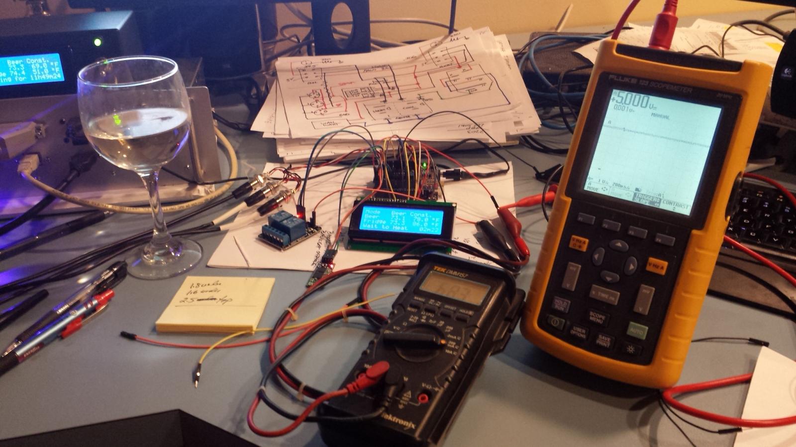
 
Ok so I did that (well turned power to the heater and fridge off at source)

went into maintenance and switched from inverted to not inverted and vice the relay clicks and light comes on/off and the display doesn't scramble.

Oh and yes it scrambles on first switch of the relay.

What I did notice was that the LCD dims very slightly when the relay switchs
 
Got it.

Very interesting - implies it's not actually the relay coil, it's the AC current surge? How is the wall wart sourcing its AC input - both hot and neutral - relative to the AC feed to the relays?

Cheers!
 
Ok now I might be defeated so bear with me.

I've effectively made a UK version of FUzzewuzze wall wart.

Live, neutral and earth comes through a old computer cable into a box where it's split into 2 wall warts.

Live is split in two and goes to the relay, and from the relay back into hot and cold wall wart socket.

Live and neutral and both split from the computer cable into live a neutral of the wall wart.

From the relay to the arduino I'm using cat 5 cable for data, power and ground.
 
Never surrender! :rockin:

Could you split out the wall wart AC feed completely from the existing AC cable and leave that to the relays and loads?

Cheers!
 
Irritatingly I'm going away for work for the next few days and need to get ready to go now so I'll have to take a break.

Thanks for all your help so far.
 
Just to make sure we're using the same terminology:

- the AC to 12VDC thingie that's powering your Uno is what I refer to as a "wall wart".

- the duplex outlet that you wired from the relays to plug in your cooler and heater is an "outlet".

So, if I read your description correctly, you have a single computer AC cable entering a box where it splits to the relays and then the two sides of the duplex outlet - and the same AC cable supplies power to the wall wart.

If you could isolate the wall wart's AC input from the rest, that might prove instructive...

Cheers!
 
I think it is already isolated or as isolated as possible.

I have 2 outlets on my wall, the first is split to power the rpi and arduino and the second outlet is what provides power to the cool/heater
 
Ok, I misunderstood the AC topology. Unfortunately that makes the root cause less obvious.

I think we'll have to table this until your return. The LCD corruption will not affect anything wrt your BrewPi scripts, so don't be concerned about that. I should have another relay module in a few days and can do some experimenting to see what might spill out...

Cheers!
 
So I've been trying to think what could be the difference between my set up and yours that creates the problem.

I can only trace it back to one thing and that's the voltage going through the relay when the circuit is created in my case this would be 230/240v and your case 110v (is that how electricity works through relays)

My relay is in a separate box a few metres away but the problem occurs no matter what the distance is.

So does this leave 2 possible causes.
1- magnetic interference that I've seen banded about in the other forum as a possible cause and that could be from a device in someone living at the end of the street.

2- the relay when switched is sending to high a signal to the arduino, due to the higher voltage travelling through the relay itself?

I might be talking rubbish, just trying to think up possible causes whilst on the road.
 
The last post on this (arduino external) thread http://forum.arduino.cc/index.php?topic=215397.0 says


Using the commonly available "Sainsmart" relay modules, you must not connect the "GND" on the relay board to the Arduino, only directly to the relay power supply. Connecting the ground to the Arduino completely defeats opto-isolation.

My ground does connect to the arduino? Is this another possible cause?
 
I'm not sure that advise is well founded.

Unless you run the Uno and everything off an actual 5VDC well-regulated power supply (which requires a slight hack to the Uno) and not via the dedicated 9-12VDC power input nor via its USB port, moving the relay board ground connection to the power supply output without moving the 5V connection as well just results in a larger loop, with the same current sharing issues that the author apparently perceived were in play.


Today I received a replacement LCD (perfect!) and another Sainsmart dual-channel relay card, have them hooked up to an Uno with one of my BrewPi protoshields, and have been doing some experimenting. No AC on the relays yet, I'm just looking for DC switching noise issues.

So far, what I know is running the Uno from a 7.5V wall wart isn't a very good choice when there are relay coils involved: when both relays were idle the Uno 5V regulator put out a perfect 5.0V. But each of the relay coils draws almost 70mA, and as soon as one relay energized the Uno 5V rail dropped to 4.75V - and the LCD backlight dimmed significantly.

On the latter count: I am intentionally running the backlight at a lower voltage (~3.4V) than the spec'd maximum (4.3V), so a big drop on the host 5V rail will show up on the display.

Anyway, the whole 7.5V thing was unintentional: I have a wall wart with selectable output and had it set to the wrong level. At a 9V setting, I can turn on both relays together (~135 mA draw) without the LCD dimming, the 5V Uno rail stays rock steady at 5.0V measured at the Uno headers. I even tried triggering the scope on a 50mV drop and it never fired.

So with that corrected, I used the BrewPi Device Configuration gui to toggle the state of the relays to see if I could inspire an LCD corruption. Never happened - as fast as I could work the gui, the LCD remained clean.

Then I configured the Cool relay to be on in BrewPi, and played with the 5V lead at the relay card to switch the relay. I could literally rattle that relay without an LCD corruption.

Bottom line, the protoshield implementation seems solid.

So, next I'm going to put a protoboard version back together just to see how susceptible that is to DC switching noise. Then I'll see about adding AC loads to the testing. Don't want to use my fridges for that, wouldn't be prudent...

Cheers!

noise_hunt_01.jpg
 
day_trippr

We had similar issues with screen scrambles on another project, mainly from switching a pump. So may I suggest using a pump as your load, as it should throw similar noise across the AC as a compressor, the other problem of course is EMI, though I see your tightly integrated set ups seem to have no such problems. In the end we placed a snuber circuit across the pump relay issue solved.

froot
 
That's a good idea re: use a pump - I had a similar notion.

The Sainsmart relay cards have snubber diodes across the relay coils, though I know nothing about the quality of the diodes used. I'm not seeing significant noise on the 5V rail when the coil discharges (or charges, for that matter), and that much shouldn't change with an inductive load across the points.

That said, I'm thinking I could use my pancake compressor to test out that theory. The startup current should be comparable, and I suspect its steady state draw may actually be higher than my fridges so that should be a respectable test load.

I have one of my two BrewPi Bluetooth minions (protoshield builds) currently running one of my 17cf top-freezer fridges for a two-batch fermentation run. That's been on-line since Friday and the display is perfect, though it's been so cold in the basement that it's probably been doing more heating than cooling.

The other minion is sitting atop the backup/testbed BrewPints crate on my desk (running test scripts at room temperature with nothing to switch) and has been subject to all kinds of random abuse, and other than the direct static zap I hit it with a couple days ago that majorly scrambled the LCD, it just keeps clicking along without issues. I'm holding back from deploying that one to my other fridge 'til the rotary encoder and P-FETs show up...

Cheers!
 
I'll try and take some photos of my setup later today, and add them.

The only thing i've noticed is you seem to have a 5th wire coming out of the back of your relay, but i'm guessing that is purely to test the rather than having a function for the Brewpi?
 
I'll try and take some photos of my setup later today, and add them.

The only thing i've noticed is you seem to have a 5th wire coming out of the back of your relay, but i'm guessing that is purely to test the rather than having a function for the Brewpi?

The Sainsmart relay module has a 3-pin header that is normally jumpered to connect the 5V input (from the other header) to the relay coil circuits. As I wanted to isolate the switched current I removed that jumper, and added another 5V connection back to the Uno/shield through my ammeter.

I don't think it would make much if any difference to always have that wire installed instead of using the jumper, but you could certainly give that a try...

Cheers!
 
Ok so as ice got enough parts to try piece together the shield I thought I'd give that a go to see whether I'll fix my screen problems.

Having soldered most of it together am i right that the 10k pot isn't soldered in a line, I.e first pin starts below the extra capacitor middle pin one row to the right and last in under capacitor again?
I think I'm getting there but it's been a challenge, hopefully be finished later tonight
 
[...]Having soldered most of it together am i right that the 10k pot isn't soldered in a line, I.e first pin starts below the extra capacitor middle pin one row to the right and last in under capacitor again?[...]
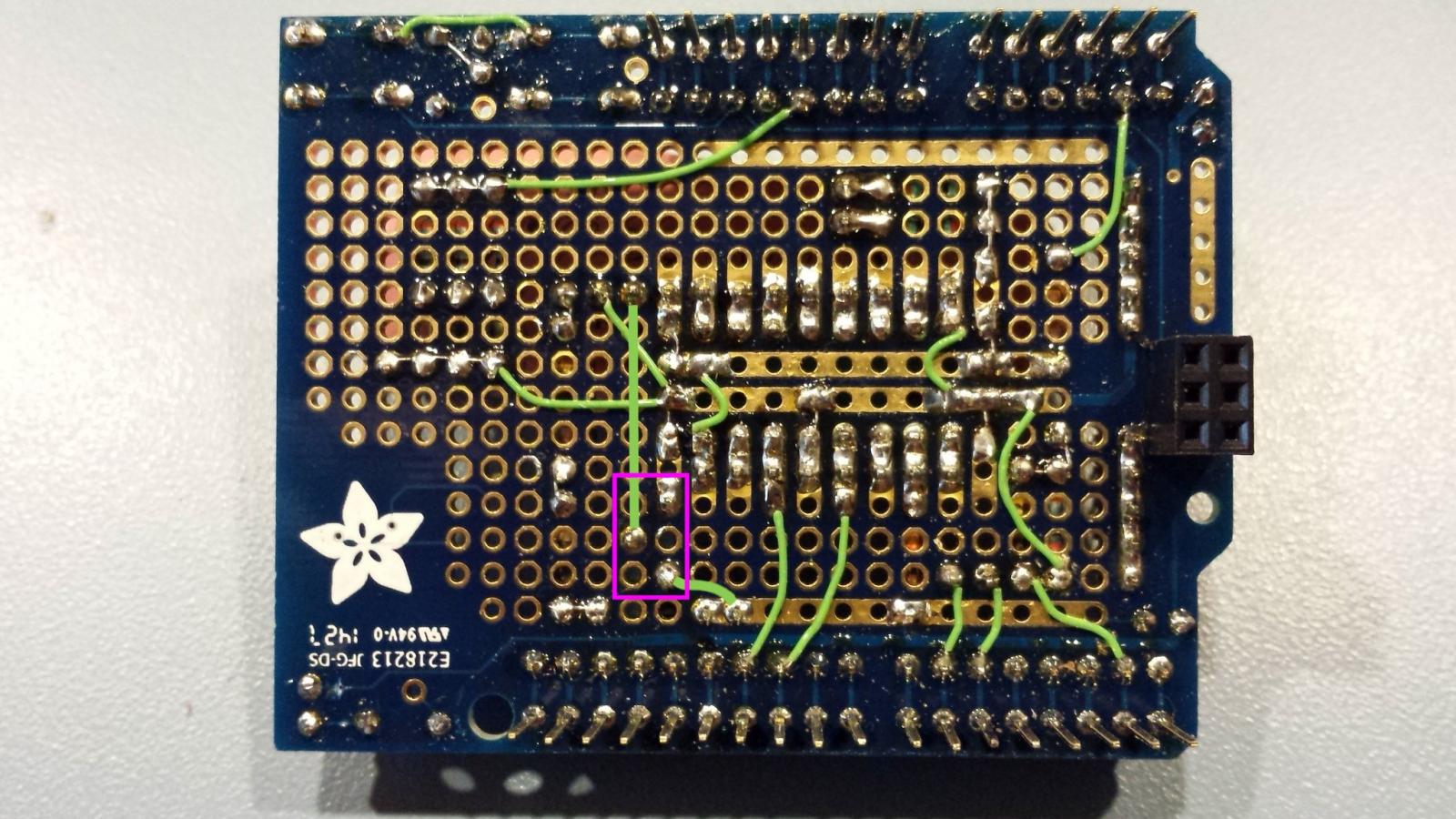
I added the pot outline so its three pins are clear. Your description sounds correct...

Cheers!

build_04a.jpg
 
There are some people in this world who are dextrous, skilled and talented when it comes to building and creating.

Unfortunately i am not one of them!

I think I have 4 wires left to solder on, if there is enough plastic left on the wires and the protoshield to create a circuit and not just one huge 5v rectangular disk I'll be pleased.

Putting the components on was the easy part, soldering all the wires in had taken me nearly 8 hours.

The other minor issue is that I have a v.5 breadboard so don't have the 6 bank of female headers towards the usb end so I'm having to do some bending of parts to utilise the 5v and ground.

This certainly isn't for the feint hearted but I've given it a good shot at least.

Tomorrow I'll finish it up and see how it goes.
 
@day_trippr Just noticed you post on the other thread re v.5 shield.

on your diagram that you only use the header to connect the power and ground to rails so figured I didn't need a full length pin so with a couple of bend in the pin I think it'll reach the arduino and still have enough metal to connect to the rails.

I'm not planning to stack anything on top of that.
 
LOL! Yeah, if you haven't done a lot of board building I'm sure this has been a challenge.

I located all the components so they'd work on either the V.6 or V.5 protoshield, so the wiring should be identical. If you like you could take a picture of the wiring side of the protoshield when you're done and I'll give it a look.

The missing 2x3 ICSP interface header on the v.5 protoshield could be a potential issue wrt power distribution. If you do a bit of "forming"* to bring the power and ground up from the Uno ICSP header to the protoshield I think you'll be that much better off. All of my builds are on V.6 boards and I'm not having any issues so far...

Cheers!

[* Back in the '70s IBM used the term "forming" in technical manuals when the actual effort being described was clearly "bending". They apparently believed "bending" was pejorative ;)]
 
@day_trippr Just noticed you post on the other thread re v.5 shield.

on your diagram that you only use the header to connect the power and ground to rails so figured I didn't need a full length pin so with a couple of bend in the pin I think it'll reach the arduino and still have enough metal to connect to the rails.

I'm not planning to stack anything on top of that.

That sounds fine. Yes, I just bring up the power and ground, so if you can do that's a plus.
I'm not planning on ever stacking another shield. It wouldn't fit in the little project boxes anyway...

Cheers!
 
hmmm somethings not right, the lCD lights up but brewpi is saying it doesn't recognise the Arduino... (re)programme it won't reprogram\

Now to find which one of my beautifully neat solders is causing the problem.
 
Just got on here and the Spousal Unit is calling me to dinner.
If you haven't found the bug when I get back I'll go through the wiring...

Cheers!
 
So it appears all the components are properly placed and oriented correctly.

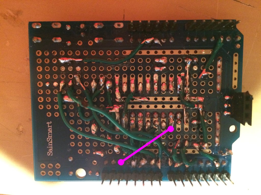
One wire appears to be missing, from header pin for IO13 to IC pin 11 (SCLK).
I drew it onto your wiring side picture.

On the Uno, there is a green LED (power good) and a yellow LED (the "blink" LED that is turned on by the BrewPi AVR sketch). Are they both lighting up when you power-on the Uno?

Cheers!

missing_wire.jpg
 
Thanks for all your help with this by the way.

They were both lighting up on the uno as far as I could tell but the LEDs on the shield were doing nothing (I've not done your tweak to the board LEDs for heating and cooling.

In terms of soldering and trying to make it easier for me, would you recommend leaving the component tailings on, before attaching the wires? the reason i ask is that i tidied up the component tails as i went along and in hindsight for my shake hands i think it would have been much easier to get everything soldered up and then do the tidying right at the very end.

I'm hoping to make the changes today, but i have to take a shed load of milk bottles and turn them into a throne for an ice princess this evening... joys of fatherhood!!!
 
Hmmm stumped powers running through the shield because the LCD backlight comes up.

The lights on the Arduino light up but the message on brewpi is that it doesn't recognise the arduino board.

I can only think I've created a short somewhere but although my solders are incredibly messy I can't see where the short occurs.

I should get a new board tomorrow hopefully so I'll plug it straight into the arduino to see if it flags any errors, and then build it up stage by stage.

Temp probes first and then the display, see how we go from there!
 
Back
Top