Help wiring an Auber power regulator please!

Homebrew Talk - Beer, Wine, Mead, & Cider Brewing Discussion Forum

Help Support Homebrew Talk - Beer, Wine, Mead, & Cider Brewing Discussion Forum:

This site may earn a commission from merchant affiliate links, including eBay, Amazon, and others.

surfologist87

Member
Joined
Nov 16, 2011
Messages
5
Reaction score
0
Location
FL
I got a new power regulator from auber [DSPR1] https://www.auberins.com/index.php?main_page=product_info&products_id=444 for my controller to replace a potentiometer.

Currently, I have a 240v system running a 5500w element. My wiring is as follows:

4 prong dryer cord for power, with a gfci, then:

Line 1 hot is going straight to element.
Line 2 hot is going to SSR, then from ssr to element. Potentiometer connected to non load side of SSR

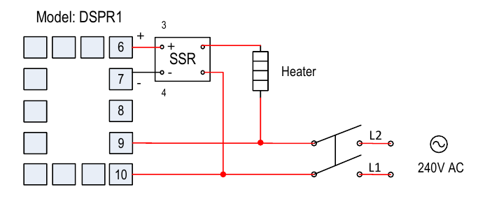
I’m changing out potentiometer to the digital power regulator and need understanding of the connection diagram provided by auber. [See page 2, upper left hand corner] https://auberins.com/images/Manual/DSPR1 manual_V1.pdf for instructions.

They have both lines going to SSR and power regulator. Only one line from there going to ‘heater’, which I believe is the element. How do I wire this, I assumed both hot lines would need to power the element to get full 240v.

I’m just a little confused. thanks!
 
Last edited:
1612035528681.png

In the drawing above, L1 goes to the SSR and then to the element, and L2 connects directly to L2. This is the same as your current wiring, except Line 1 and Line 2 are swapped (which doesn't matter.) The switch needs to be a 30A rated DPST (a Leviton 3032 is suitable.) Your current design does not have the switch, but I highly recommend including the switch.

Not sure if you know this already, but you need to replace your potentiometer controlled SSVR, with a low voltage triggered SSR (should be zero crossing triggered as well.) An Auber 40A SSR is a good choice.

Brew on :mug:
 
View attachment 716462
In the drawing above, L1 goes to the SSR and then to the element, and L2 connects directly to L2. This is the same as your current wiring, except Line 1 and Line 2 are swapped (which doesn't matter.) The switch needs to be a 30A rated DPST (a Leviton 3032 is suitable.) Your current design does not have the switch, but I highly recommend including the switch.

Not sure if you know this already, but you need to replace your potentiometer controlled SSVR, with a low voltage triggered SSR (should be zero crossing triggered as well.) An Auber 40A SSR is a good choice.

Brew on :mug:
Awesome thank you. So I wired it up as shown and the regulator powers on and I can cycle from 0-100%, however my element seems to only be pumping out 100% power. Any idea why? Elements is heating water even if the power regulator is not on. So somewhere my wiring is wrong.

I believe my SSR is a true SSR. that’s what I ordered a long time ago and that’s what it says on the unit.. ill google the model number and double check.

edit. Looks like an SSR I believe. this is the unit I have https://www.amazon.com/dp/B01M0IU1AX/ref=cm_sw_em_r_mt_dp_FR7WHE9ME72YMMBCMR05
 
Last edited:
The item you linked is an SSVR (solid state voltage regulator) not an SSR. It requires a potentiometer to control it. The 470K resistor symbol at the control inputs is the give away. The label at the control inputs needs to say "3 - 32V DC", or similar.

I'm not sure, but it's possible that hooking a DSPR1 up to an SSVR could damage the DSPR1. If you have a voltmeter, disconnect the SSR/SSVR from DSPR, set the DSPR to 100%, and read the voltage between terminals 6 & 7 on the DSPR. Should read several volts. Then set the DSPR to 0% and measure the voltage again. It should read about 0 volts. If either of these readings is off, then your DSPR may be damaged.

Brew on :mug:
Shoot man I was hoping I didn’t fry it. I checked with a multimeter and it looks to be operating correctly. Thanks for helping me learn how to test it.

So the VA on that SSR made me think SSVR was a possibility. Thanks for clearing that up. I did order the correct one and will find out when it comes tomorrow.

Do you think that is the only problem, why my element was going full blast no matter what setting it was on? Even with the regulator off, my element was on heating water. Thank you friend
Yes, I believe that is why you weren't getting any power modulation of the heating element.

Brew on :mug:
 
Back
Top