Help wiring 240v motor for grain mill

Homebrew Talk - Beer, Wine, Mead, & Cider Brewing Discussion Forum

Help Support Homebrew Talk - Beer, Wine, Mead, & Cider Brewing Discussion Forum:

This site may earn a commission from merchant affiliate links, including eBay, Amazon, and others.

adamrduley

Member
Joined
Jul 11, 2011
Messages
12
Reaction score
1
Location
Austin
Hello,

I am having a very difficult time correctly wiring my grain mill motor to correctly reverse directions and would appreciate some help.

Here are the details:

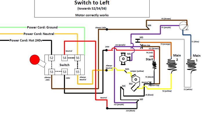
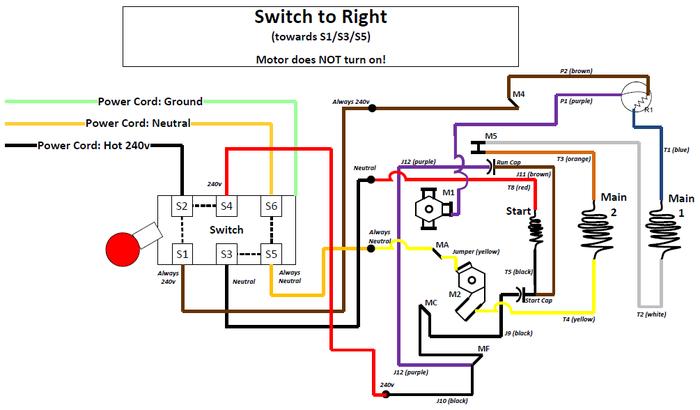
The motor correctly works when the drum switch is in the left position (when looking at it from the handle side) but nothing happens when it is in the right position.

I'm very stuck and could use help!

Thank You!
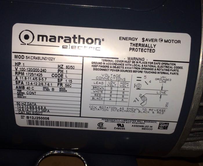
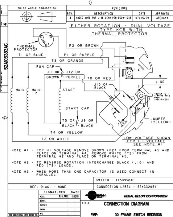
MotorLabel.jpg


MotorSchematic.jpg


SwitchPositions.jpg


SwitchToLeft.jpg


SwitchToRight.jpg
 
I don't think you can safely do it with that drum switch alone. That switch could be used to swap J10 and T8 but it can't also interrupt the power to M1 and M2 (or even just the power on M1.)

One solution would be a drum switch with more poles.

Another would be to use that switch only for the forward/reverse (not the center off) and add a master power switch in the supply line. In this case, the drum switch would be connecting between M5 and T8 and between MA and J10 such that T8 and J10 are swapping.

Or, you could use the drum switch to both interrupt the power and drive a contactor to handle the forward/reverse circuit switching described above.


Here is some discussion of a similar configuration:
http://www.doityourself.com/forum/electrical-ac-dc/490053-help-forward-reverse-drum-switch-wiring.html


By the way, in your diagrams you show power being applied at M4, that is bypassing the thermal protection. In your 240V application power should only be applied at M1, it then passes via P1 to the protector and then out of the protector on T1. The Brown wire on P2 isn't used in a 240V application so it is moved to M4 just as a safe place for it to rest.


I hope I've worded this well enough to be helpful and not add further confusion/frustration.
 
To expand a bit...

If you decide to go with a separate master power switch before the motor, then you need to be sure to turn it off before changing the direction with the drum switch. To eliminate the possibility of switching the drum while the motor is running, it is preferable to use one of the other solutions.


One more solution, probably what I would do if I had your materials on hand:

1. Add a master safety disconnect switch in the supply line.
(edit for clarity) Connect the supply to M1

2. Connect T2 (White) to S1

3. Connect S2 to M5

4. Connect T8 (Red) to S3

5. Connect J10 (Black) to S4

6. Connect S5 to MA

7. No connection to S6

8. (edit for clarity) Connect P2 (Brown) to M4

This should give you full and proper functionality from the drum switch (including center off). For safety though you do need a master switch to de-energize the components that are in line before the drum switch.
 
Thank you for the quick response!

The grain mill connects to my control panel box that I built (followed plans from theelecticbrewery.com) which has an external switch that will control all power to the grain mill.

Will try out your suggestions tomorrow morning when I get back home

Thanks again!
Adam
 
Hello,

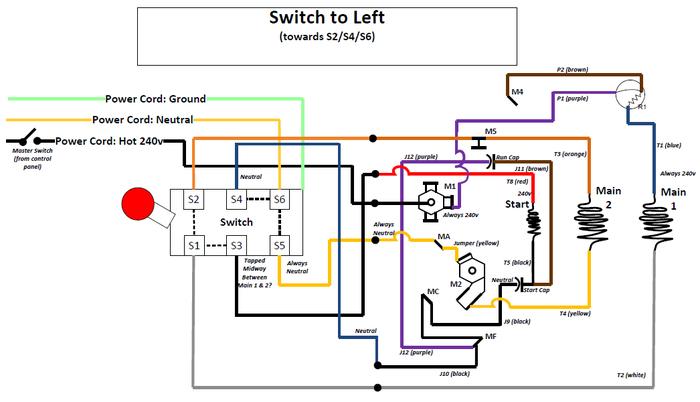
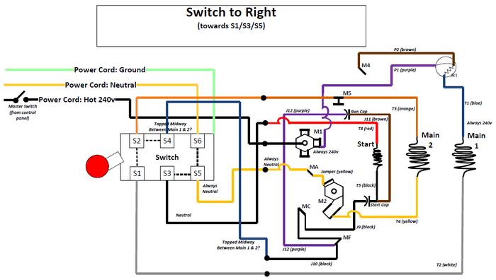
So I drew up your final recommended solution. Looks like you are using S1->S2 connection to make the motor coils always be in series and T4 connects to MA and then to S5 to neutral. That all makes sense to me.

I'm curious as to why S4/S3 get connected midway in-between the main motor coils? Can you verify I drew up what you envisioned?

Thank you

SwitchToLeft_Reynolds.jpg


SwitchToRight_Reynolds.jpg
 
Looks like you have it almost correct in the drawing. The neutral connects to M2. Nothing on S6.


The connection at the mid point of the coils has to do with the way this motor is configured for use on either 120V or 240V. On 120V the two main windings are in parallel. For 240V the main windings are in series. In the 120V configuration the start winding is also in parallel but for 240V it connects at the mid point so the two main windings act as a voltage divider.


Your drawing shows MF and MC connecting together. That is actually a switch inside the motor that breaks the connection between MF and MC once the motor is spinning, so that the Start Winding is disconnected from the circuit after it starts.


To reverse the motor, the two ends of the Start Winding are reversed. So the switch is being placed in the circuit where it will allow the start winding to be reversed. It will also interrupt the flow through Main Winding 1 and Main Winding 2 so that the center position stops the motor.
 
Ahh, makes sense about the voltage divider, and want 110v potential across the starter coil.

The MC-MF connection was just me trying to duplicate the schematic (that is not a connection I made). So yes, makes sense about it being a switch.

So, i tried out the motor with this setup and unfortunately nothing happened in all 3 positions of the drum switch. I verified I have 220v at M1. I measured the voltage across M1-T2 and I get 220v with 3.8kOhm resistance. I then measured M4-T2 and I get 0v with 1.2Ohm resistance. The 1.2 ohm resistance makes sense since you'd expect to see some small resistance across the coil.

Any suggestions of what to try/measure next? I'm tempted to try connecting the hot line to M4 rather than M1. Or maybe it should go to both M1 and M4? If you look at the label of the motor from my 1st post, it says for high voltage brown should go to M4 (and ungrounded line to M1)
 
Connecting power to M4 will just bypass the protector.

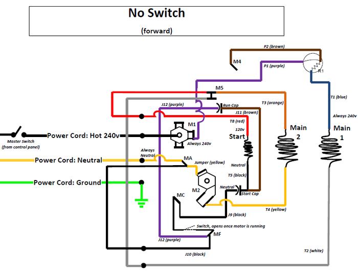
Have you done a test of the motor without the switch? You should be able to connect hot to M1, and neutral to M2 and have it run. Then disconnect power, swap T8 and J10, power up and it should run in the other direction.
 
Since the motor worked in the forward direction with my original configuration i have not tested without the switch. With that said, i've never seen it turn in the opposite direction.

I like your idea of simplifying things by removing the switch to make sure the basic functionality can be achieved without the switch.

I will try tonight after work (~1pm EST)
 
If the No Switch configuration works, then simply swap J10(black) from A to 5 and T8(red) from 5 to A and it should reverse direction. Keep in mind that supply voltage should be removed completely when performing the swap and the motor allowed to come to a halt before applying voltage again.

FWIW, there is no neutral conductor in this single phase 240V configuration. The two conductors are more appropriately labeled Line1 and Line2 or Hot1 and Hot2. They both have 110v potential relative to ground and should both be switched open for disconnect.
 
Here is what i plan to try tonight. This should match the original schematic.

Yes, start there.


FWIW, there is no neutral conductor in this single phase 240V configuration. The two conductors are more appropriately labeled Line1 and Line2 or Hot1 and Hot2. They both have 110v potential relative to ground and should both be switched open for disconnect.

You missed where in the first post he noted that his location is currently "in Europe".
 
Great! Going back to the basics was a good idea as was able to get it spin in both the counter-clockwise (Black(J10)=MA, Red(T8)=M5) and clockwise (Black(J10)=M5, Red(T8)=MA).

However, i had to bypass the thermal protector. When i connect my hot 240v line to M1 nothing happened in either direction. I then moved it to M4 and that is what allowed it to work. I'm afraid i might have damaged the thermal protector in all my experiments i did prior to getting your advice.

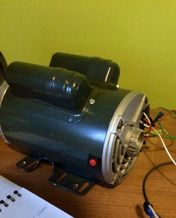
I tried pushing the red exterior red button (see attached image) on the motor, hoping it would reset the protector but that didnt seem to do anything.

Opinions on simply running the motor bypassing the thermal protector?

I'm going to start re-wiring the motor to have the external drum switch just as we had it before, but with hot 240v going to M4.

MotorResetSwitch.jpg
 
Yes, start there.


You missed where in the first post he noted that his location is currently "in Europe".

That's correct, I'm currently living in France (even though my hometown is Austin, TX as my profile says) so i do have a 240v hot & neutral, whereas if i was back in the states i'd have the differential across the two out of phase hots.
 
I guess that if it was me, I would be tempted to run it without the thermal protection until I could purchase and instal a replacement protector. I would put a properly sized slow blow fuse in line to provide some protection before loading it with grain. Be sure to stay close by whenever it's running so you can shut it down quickly if needed. And don't run it so long that it gets too hot.

The label says it pulls 5.7 amps at 240V. Select a slow blow fuse rated not too much higher than that. You may want a couple of different ratings on hand in case it blows too quickly - higher ambient temperatures can derate a fuse.

Hopefully you're on track now
 
Woohoo, the switch fully works now!

Thank you David so much for your excellent explanations, I was lost without your help. I really do appreciate your time. If you're ever visiting the south of France let me know, i owe you a few beers!

Thanks,
Adam
 
Glad I could help! I've learned so much about brewing here I try to give back where I can. This one was an interesting challenge. I had to study the motor drawings a few times to figure out what was going on in the 240V configuration.

By the way, looks like you were right about needing to go around the protector. I just didn't want to believe it at first.

Kevin
 
This morning I connected the motor to my speed reducer and mill. Everything seems to be working.

Going to try to find some time delayed fuses at the hardware store here and test it with some grain tonight

ImageUploadedByHome Brew1406614253.394365.jpg
 

Latest posts

Back
Top