Float Switch wire protection

Homebrew Talk - Beer, Wine, Mead, & Cider Brewing Discussion Forum

Help Support Homebrew Talk - Beer, Wine, Mead, & Cider Brewing Discussion Forum:

This site may earn a commission from merchant affiliate links, including eBay, Amazon, and others.

JayMac

Well-Known Member
Joined
Jun 20, 2012
Messages
274
Reaction score
12
Location
Guelph
Hey everyone,

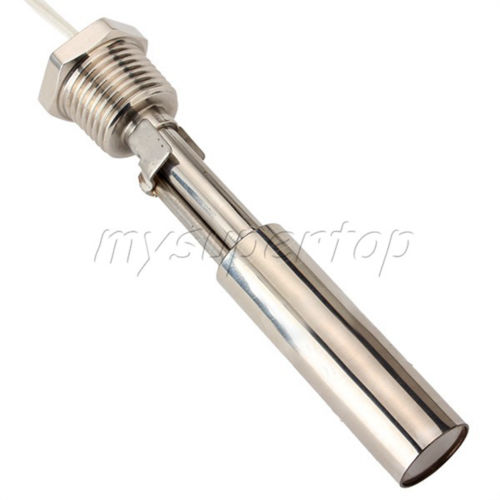
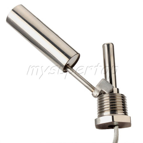
I bought a couple float switches from China for like $12 each w/ free shipping the other day. The only problem is that I'm really worried about the delicate wires getting ripped out by accident. The switch is unlike many of the float switches you tend to see on the internet; it only has one set of threads (while others will have two, one for entering the kettle, one for outside the kettle). This makes protecting the wire very difficult. I have attached two pictures of the switches.

They are all stainless steel w/ 1/2" NPT threads. I plan to thread this in to a 1/2" female NPT tri clover fitting, and solder on a triclover flange to my HLT and BK. This gives me complete control over its orientation (no problems with the threads tightening when switch is upside down) and makes removal for cleaning very simple. The only problem is that it lacks a strain relief, or anything that would even allow me to connect a strain relief!

The only thing I can think of is to use shrink tubing that will fit over the hex portion, which will alleviate strain from the wires to the fixed nut. Are there any other ideas out there? Ideally I would like to somehow solder on a female QD, but I don't see how I could do that.

Thanks for the help,
Jay
FloatSwitch1.JPG


FloatSwitch2.JPG
 
Run some tape around the flats of the housing for a form and then fill the inside of the form where the wires come out with J-B Weld thus creating your own strain relief.
 
Run some tape around the flats of the housing for a form and then fill the inside of the form where the wires come out with J-B Weld thus creating your own strain relief.

Do you mean to tape around the hex shaped nut, so that it extends parallel to the wires (essentially creating a cup). Then filling this cup with the J-B weld? I'm assuming this would adhere to the SS surface.

Seems like a pretty good idea. I wonder if I can get a hex shaped plastic tube that can serve the same purpose as the tape... just to make it look a bit better.
 
It would be prudent to terminate the control panel end of the wire with a connector such as barrel connector. This way you can disconnect it from both the kettle and the control panel.
 
It would be prudent to terminate the control panel end of the wire with a connector such as barrel connector. This way you can disconnect it from both the kettle and the control panel.

This is what I intend on doing. Which connectors do you suggest? I assume the wires for the float switch will be relatively short, so I will need to extend them, and probably use shrink tubing for insulation up to the quick disconnect at the control panel.
 
This is what I intend on doing. Which connectors do you suggest? I assume the wires for the float switch will be relatively short, so I will need to extend them, and probably use shrink tubing for insulation up to the quick disconnect at the control panel.

I used simple mono audio connectors for mine.
 
Run some tape around the flats of the housing for a form and then fill the inside of the form where the wires come out with J-B Weld thus creating your own strain relief.

Go one step further, and run your switch leads in 1/4" or 3/8" i.d. armored, flexible conduit and embed that in the epoxy.

Would be an fairly easy way to really make a professional looking installation.

Untitled.jpg
 
Go one step further, and run your switch leads in 1/4" or 3/8" i.d. armored, flexible conduit and embed that in the epoxy.

Would be an fairly easy way to really make a professional looking installation.

Yes... I like this idea. Would you recommend just the conduit in to the J-B Weld? Or a conduit fitting which would clamp on to the conduit? It seems using the fitting might create a stronger connection, and would probably make the whole thing look better.

I also like the idea of using the coaxial connectors, as they allow me to use conduit.

How would you recommend connecting/splicing the wires to extend the switches leads? Twist-on connectors are too bulky to fit inside smaller conduit. Would an inline splice covered by shrink tubing be the best solution?

Unless you think you would be replacing the conduit at a later date, I would probably just pot the conduit directly in the epoxy. Epoxy bonds so well that you will really have a permanent connection.

I would solder extension wires directly to the float switch leads and then insulate them with heat shrink tubing. That makes a really low profile splice that's not much larger than the wires themselves. When properly soldered, the connections are extremely reliable.
Butt splice crimp connectors would be my next choice.
 
Hmmm, would this idea work....

An XLR chasis mount for the control panel:
http://www.vetco.net/catalog/product_info.php?cPath=72_92&products_id=11392

A 10' XLR extension cable:
http://www.vetco.net/catalog/product_info.php?cPath=37_59&products_id=7666

Cut off female end of the XLR cable, splice the exposed wires with the leads from the float switch, covering each wire with heat shrink, and a second round of heat shrink to cover both wires.

Then, use J-B weld to fill the hole where the float switches wires emerge. You can see this hole in the attached image. Do you think doing this would allow the epoxy to bear the majority of the stress if the wires are pulled? Or should the epoxy be built up in a cylinder extending from the hex shaped nut? Intuitively, it seems that as long as the epoxy can grip the wire, it should be fine, as the stress would be directed towards the metal face.

I like the XLR connection because it is a little more elegant and requires only one connection at the panel

FloatSwitch1.JPG
 
Looking at the float switch, it's a little hard to tell what the hole dia. and depth are.
I am doubtful you could get a good bond, just based on what I can see in the pic.
 
This is what I intend on doing. Which connectors do you suggest? I assume the wires for the float switch will be relatively short, so I will need to extend them, and probably use shrink tubing for insulation up to the quick disconnect at the control panel.
I am in the process of wiring a float sensor up in my HLT.
I decided to mount a small outlet box on the side of the kettle to protect the wires and I will have the plug mounted into the side as well as an led that will go out if the float sensor opens and kills element power... I also have a small pwm speed controller I and mounting in the same box to control a motor that powers a stirbar to keep my hlt water circulated. both the floatswitch and 24v power wiring are coming through a single "4 pin" xlr connector I bought for 99 cents on ebay...
 
personally, I think XLR connectors and cables are a little overkill for this type of application but if you've got money to burn, go for it

thats what I use... 12mm xlr connectors are 99cents.... I would hardly call it overkill. if you buy from overpriced marked up US distributors then maybe... its nice to be able to remove the kettle if needed without wires hanging from it. only I use them at both ends like I do for the temp sensors.
 
thats what I use... 12mm xlr connectors are 99cents.... I would hardly call it overkill. if you buy from overpriced marked up US distributors then maybe... its nice to be able to remove the kettle if needed without wires hanging from it. only I use them at both ends like I do for the temp sensors.
augie, might be a good idea to post a link to your cheaper connectors cause the ones op posted are seriously expensive :mug:
 
Quickly searching on amazon there are chassis mounts for $2 and extension cables for $7 - no need to give me a link! I'm definitely willing to pay under $10 for each float switches wiring, so I'd like to move on with this idea of using XLR!

processhead, how do you suggest increasing the surface area? I was thinking of trying to find a polyethylene cap... hopefully individually and not in large packs as shown below

(http://www.amazon.com/dp/B006H9RX44/?tag=skimlinks_replacement-20)

OR

(http://www.mcmaster.com/#hex-nut-caps/=url3mi)

1/2" NPT threads are .84" in dia, and the hex portion is a little larger. If this 0.866" cap is even close to fitting (probably would with some sanding), I could slide it over the shoulder of the hex, cut off the circular top (for mcmaster cap), fill the cup shape formed with epoxy, and that should provide a nice looking strain relief around the cord.

thoughts? suggestions?

Thanks for the help!
 
Last edited by a moderator:
Run some tape around the flats of the housing for a form and then fill the inside of the form where the wires come out with J-B Weld thus creating your own strain relief.

I would make the epoxy form as described by timpoulen.

Then set the switch in a vice to hold everything vertical. Run the extended leads through the flexible conduit.

Position the conduit in the form you made with tape. Temporarily support the conduit as needed to position and stabilize it.
Pour the epoxy up to the edge of the tape and walk away for 24 hours.
 

Latest posts

Back
Top