diy Fermentation chiller using PIC 16F877A

Homebrew Talk - Beer, Wine, Mead, & Cider Brewing Discussion Forum

Help Support Homebrew Talk - Beer, Wine, Mead, & Cider Brewing Discussion Forum:

This site may earn a commission from merchant affiliate links, including eBay, Amazon, and others.

cell

Well-Known Member
Joined
Feb 17, 2008
Messages
102
Reaction score
2
Location
Montreal, Canada
Here's my fermentation chiller. The construction of the box is based on the 38dd fermentation chiller by J. Thornton. However, instead of using the regular thermostat, I built my own. Now I could simply use a comparator circuit to trigger a relay, but I really wanted a programmable thermostat. The system is pretty simple and it is probably overkill to use a 16F877A uC. On the other hand, this uC features an analogic-to-digital converter and PWM support. Plus, this uC can be "bought" as samples for cheap. It works like a regular thermostat, if the temperature is above 18C, the fan turns on. Otherwise it turns off. I plan to use it for ale fermentation.


If there are people interested, I can post the source code and schematics online.


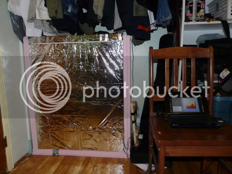
Anyways, here are the pictures of the fermentation chiller (only the box):
P1040230.jpg

Inside
P1040231.jpg


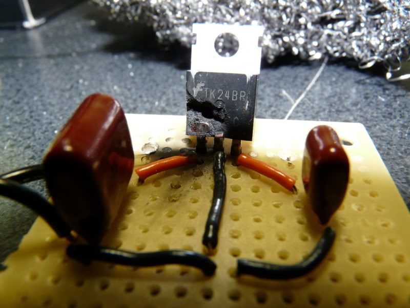
Now here's the circuit board:
Basically, I'm using a 120mm 12V fan, a 16F877A uC and a LM35 for temperature sensor.
P1040224.jpg

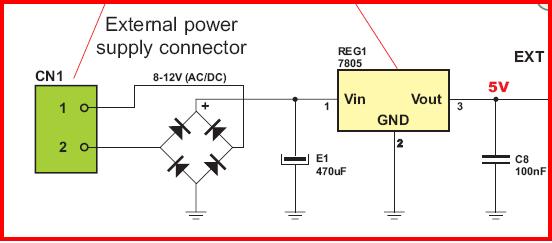
12V/5V circuit board
P1040252.jpg


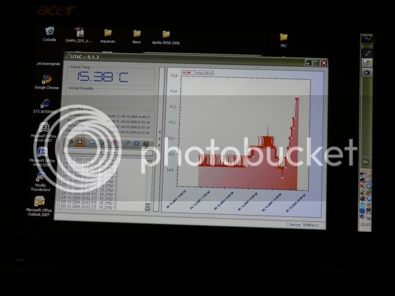
Now here it is in action (using usb temperature probe):
P1040254.jpg

P1040250.jpg


Now here's the funny part, blown components; when wiring the power supply, I supplied by mistake -12V to the 5V voltage regulator, which exploded!
P1040247.jpg
 
In the spirit of this forum, not only should you provide the source code, a bill of materials should be supplied. And I shouldn't have to ask. (J/K) I am interested in both though, as I'm trying to learn as much as I can about electronic circuits. I don't know if it's simple or not but it looks like a good learning project. A schematic would be awesome too, if you have one.
Is this a stand~alone unit or does it have to be connected to the computer im order to function?
 
I too would like to know what components/schematics went into this project. I attempted to do a similar project with a Cypress Semiconductor Microcontroller, but also mixed up the supply voltages, leaving me with nothing. I'm curious to see the details of this project. Thank you in advance.
 
I appreciate the info. I'll have to see if I can get one up and running in the next few months.
 
I always use the following setup for voltage regulation to avoid exploding voltage regulators. Plus the fact that you can use both AC and DC transformers. And it doesn't matter how you connect the transformer if it's a DC (i.e. + could be connected to either 1 or 2 ((CN1 1, 2 in the picture)) and ground as well)

voltage_regulation.JPG


BTW...LM35, that's an analog temperature sensor right?

A bit of overkill to use a 16F877A, but it leaves you with loads of free ports for future usage. :) Using the same PIC in my temperature sensor, although I use the digital DS18S20 temperature sensor.

Would be fun to see code. :)
 
I always use the following setup for voltage regulation to avoid exploding voltage regulators. Plus the ...
This is a good "fool-proof" circuit indeed! I was a little too much confident when I wired my circuit. I had two wire coming from out of the transformer and one of them had a white dotted line on it (- - - - -), I thought this was the (-) ground... it wasn't!


No real need for a processor. There are fan speed controllers that take a thermistor input and drive a PWM output. Look at the TC648. www.digikey.com stocks everything, and you can get the datasheet there. I used this part several years ago.
That's interesting. I wonder if you can power a Peltier unit using these fan controller...hehe


As for the PIC programming, basically I used this programmer: http://feng3.cool.ne.jp/en/pg5v2.html

I'll try to post the schematics later..
 
Back
Top