Displaying Potentiometer (PWM) Values

Homebrew Talk - Beer, Wine, Mead, & Cider Brewing Discussion Forum

Help Support Homebrew Talk - Beer, Wine, Mead, & Cider Brewing Discussion Forum:

This site may earn a commission from merchant affiliate links, including eBay, Amazon, and others.

SilverZero

Well-Known Member
Joined
Sep 6, 2011
Messages
1,013
Reaction score
109
Location
Bend
Hey all, I'm starting my control panel build and I'm incorporating an analog potentiometer-based PWM (LED dimmer from eBay with some mods to slow the pulse rate to about 1Hz) for the boil kettle. I'd like to add some sort of display to show the potentiometer position.

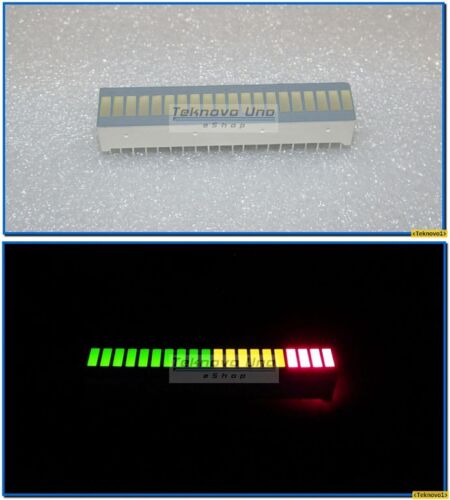
I was thinking of using an LED VU meter, but I'm not sure if I'd have to interface them via an Arduino and the analogRead function or what. I'm a beginner when it comes to programming but I could figure it out with the right keywords to Google. Or is there a more direct way to measure the potentiometer output?

I had also considered displaying on a two-digit 7-segment LED display but I couldn't find any displays like that, but if I could I'm sure I could use analogReadSerial and then output the 0-1023 values in increments from 0 to 11 (because of course it would go to 11).

$_57.JPG


$_12.JPG
 
If the output is PWM, then analog sensing will not work.

I like the idea of using a knob to control the boil, but I think without a digital solution, you will have to settle for the little white line on the knob.

-BD
 
If the output is PWM, then analog sensing will not work.

I like the idea of using a knob to control the boil, but I think without a digital solution, you will have to settle for the little white line on the knob.

-BD

Not quite true, it is pretty easy to build a simple low pass filter (a resistor and a capacitor) to make the pwm into a nice smooth 'analog' voltage.
 
You can try a few different things. The problem is the relevant parameters of the signal you are measuring is unknown. This makes it impossible for somebody to calculate, draw a schematic and give you a parts list and tell you expected results.

Having said that, if you want to engage in trial and error, you can get a meter to light up and display numbers. As said earlier, you would get a numerical display that would roughly be the equivalent of the white line on the knob.

Assuming you have a digital volt meter, put it on AC Volts and measure the range, highest to lowest.

Most simple solution. The highest value measures that range. Get an AC volt meter that has that range in it's capability. Do not surprised when then two meters measure different values, get a meter and round up. You will know that (I make up a number here) .384 volts = 100% and 0 volts = off. And the values in between may or may not be linear values. You could pad down the signal into the meter such that it reads an even number like .300V, .200V or .100 V.

If you want it to give you a more meaning value, like 1.00 = 100% and 0 = Off, then you are going to engage in trial and error. You can construct a circuit with a handful of parts, some bench time and a couple trips to the electronic parts store that would give you an even number as 100% and 0 = off.
 
I got a couple of these for under $10 a piece to control the tan DC wort pumps. Works pretty good. I haven't hooked it to a scope yet to see what the frequency is yet. Of course this will drive an SSR, so the 60 hz will be chopped at the cycle level, so zero crossing SSR would not work.


Edit; Looks like this type will not help you in your case for a standard Triac type SSR. Sorry about that.
http://www.ebay.com/itm/Motor-DC-6-...066?pt=LH_DefaultDomain_0&hash=item3ced3d6f02

Pump as reference:
http://www.ebay.com/itm/New-DC-12V-...t=LH_DefaultDomain_0&var=&hash=item541703de54

To do it in analog you would use a RC network to convert the PWM to a DC level, which would drive a buffer OPamp, which would drive a resistor divider network connected to a comparator for each of the LED segments. each comporator would have a voltage divider on the reference input set for the voltage that would turn on the segment.

edit: You can tap off the pot to sense position using the A/D of the micro, but it could interfere with the device, so you may need to buffer the signal with an OpAmp. So using the micro's timer/counter feature to measure the PWM would be better method.

edit: All digital using a microcontroller would be more direct and better approach. interrupt on the PWM and measure the pulse width with the timer. quantize the number of LED segments over the period of the PWM and enable the appropriate segment. To limit power through the micro you would want to scan the LED segments so only one is on at any time but for the human eye the enabled LED segments look to be lit continuously.
 
True but the tuning, linearity, and calibration will make this a bit more heady of s solution.

-BD

I don't think so. The low pass filter makes the signal into a proportional voltage. The PWM frequency is lower than mains (for the SSRs), so the the voltage is directly proportional to the power draw.
Where would you need to tune or calibrate? Where is the non-linearity?
You just need a sufficiently large capacitor and resistor and hook up to the VU meter. You will probably need to look up reasonable values for C and R at the frequency though, but that should be easy.
 
Possible, absolutely. Practical... likely no unless the OP has basic circuit skills, testing tools, and access to a range of parts. The time spent figuring this out might not be worth it, depending on what he wants to do. If it were me I would suggest an inexpensive PID controller, and run it in duty cycle mode. $15 and done.

Now if you would like to propose specific part numbers and transcend the hypothetical to the tangible... that would be a real solution for the OP.

-BD
 
If I understand this correctly you have a device which, given a DC input of V volts, outputs a pulse of V volts amplitude at a PRI of one per second with width determined by the knob position and these pulses are passed to an SSR gate. You wish to get an indication of the knob position or really the percentage power output. If that is correct a relatively simple solution might be to cobble up a 'leaky integrator' using an op amp, a capacitor and a couple of resistors. The ratio of the resistors determines the 'dc gain' of the thing. If they are equal, the device is set for 100% and the input voltage is V then the output voltage will be V. As the duty cycle goes down so does the output voltage but not immediately. The product of the feedback resistance and capacitance (in parallel with the feedback resistor) must be appreciably more than 1 second and that means that if you go from full on to full off the output voltage will decrease from V to 0 over a time period of several seconds. It is a low pass filter but after a couple of time constants it outputs the linearly scaled DC content of the input pulses (duty_cycle*V) and this can be displayed on any kind of analogue meter, sent to an A/D... As you have control over the gain clearly you can select a display device such that it shows 0 - 100% (or 0 - 11 if you prefer).

If you want a faster responding meter you will have to do something like use the leading edge of the pulse to reset a counter and the pulse itself to gate it. This is going to be sticky if there is no pulse when set to full on (i.e. if the output is continuous DC under those conditions). It's still doable if the counter is gated on by the pulse but the interval at which it is reset is determined from another source, for example if you admit clocks to the counter for a period of some seconds determined by a timing circuit. The difficulty here is that you don't have (without a finite off time even at 'full on') any means of synchronizing the counter and PRI and thus must use a several second counting period which gets back to the long delay. If you can synchronize you can get an answer every second.

Further note: many of the popular processor chips contain onboard counters.
 
I got a couple of these for under $10 a piece to control the tan DC wort pumps. Works pretty good. I haven't hooked it to a scope yet to see what the frequency is yet. Of course this will drive an SSR, so the 60 hz will be chopped at the cycle level, so zero crossing SSR would not work.

http://www.ebay.com/itm/Motor-DC-6-...066?pt=LH_DefaultDomain_0&hash=item3ced3d6f02

Interesting, I'll consider that as well. 16kHz is a really high frequency for a boil element, although I've done it before.

To limit power through the micro you would want to scan the LED segments so only one is on at any time but for the human eye the enabled LED segments look to be lit continuously.

Ah, good idea. That sort of addresses the conundrum I was facing with thinking about using an Arduino to read the pot position and then write LED values on the meter. I've seen how to dim just one LED fairly easily, so it might be pretty simple to scan a strip of them up to a certain level based on voltage.

Although I think I'm leaning toward the Auber solution for aesthetics, I still love DIY projects.
 
What if he puts an AC voltmeter across the input to the heating element?

Too many variables to predict how accurate it would be in absolute RMS values. He would know what the top reading is and the zero point is. In between you could not count on it being linear. He could learn what values he likes to use. As in "For rolling boil, I set to 186."

He could also pad this AC voltmeter, have it say 100 at full power, then as he turned it down the reading would go down. The read out value may not be linear and literally accurate, but i would give him a repeatable numerical reference.
 
Interesting, I'll consider that as well. 16kHz is a really high frequency for a boil element, although I've done it before.


Ah, good idea. That sort of addresses the conundrum I was facing with thinking about using an Arduino to read the pot position and then write LED values on the meter. I've seen how to dim just one LED fairly easily, so it might be pretty simple to scan a strip of them up to a certain level based on voltage.

Although I think I'm leaning toward the Auber solution for aesthetics, I still love DIY projects.

If you just want to drive a bar of LEDs, you can do that with an LM3914. You'll need a filter or integrator as described above, then a voltage divider to scale the max voltage to 5V. Or you can feed the PWM into an LM2917 frequency-to-voltage IC.

http://www.ti.com/lit/ds/symlink/lm3914.pdf
http://www.ti.com/lit/ds/symlink/lm2917.pdf

If I were designing it, I'd just use any small microcontroller and use the internal timer to measure the frequency and drive a numeric display. For home brewing though, sure seems like there must be a canned solution that doesn't require any DIY at all - PWM meter of some kind.
 
Possible, absolutely. Practical... likely no unless the OP has basic circuit skills, testing tools, and access to a range of parts. The time spent figuring this out might not be worth it, depending on what he wants to do. If it were me I would suggest an inexpensive PID controller, and run it in duty cycle mode. $15 and done.

Now if you would like to propose specific part numbers and transcend the hypothetical to the tangible... that would be a real solution for the OP.

-BD

Hey man, I know that tone is hard to convey on a forum, but I geniunely was asking about what non-linearities and calibration needs you were referring to. I don't want to step on any toes or start any debates.
As for getting a PID and so on, that is not what the OP was asking for. He was asking for a solution to a pretty specific problem.
As for selecting R and C values, then this site could be of help
http://sim.okawa-denshi.jp/en/CRlowkeisan.htm.

BUT, then it hit me... Why cross the bridge for water....
On the middle lead of the potentiometer, you set the the desired voltage for use with the comparator in the LED dimmer.
The easiest solution IMHO would be to use this to directly drive the VU meter (depending on the input impedance of the VU meter, but I would think that for a well designed one it would be high, so you could drive it directly).

Edit: You could of course use this as input to analog to digital converter in an arduino as well, to get a direct reading of the pot and show the value on 7 segment LEDs as otherwise requested.
 
What is the function of the meter? How much resolution does he need?

I am trying visualize the application. Seems to me on a boil kettle, you want to turn it up 100% to get to a boil, then set it to the sweet spot of rolling boil, but but not boil over. Are there other set points he wants to use?

He is going to be putting his hand on the knob and turning it down, how does he know when to stop? Initially the stop point is arrived at by trial and error. He will not know he wants 87% or 76% or 63.2% or what ever. He will turn it down to the point he likes, then observe and note the value.

Back in my recording studio days, we put a hunk of tape next to the fader and when we got the bass where we wanted it, we put a mark on the tape. If he does not need many set points on his pot, he is a piece of tape away repeatable results.

If he wants the visual of a meter, digits going up and down, many ways to skin that cat. Depends on his tech abilities, budget and patience to go with trial and error.
 
Hey man, I know that tone is hard to convey on a forum, but I geniunely was asking about what non-linearities and calibration needs you were referring to. I don't want to step on any toes or start any debates.

There's going to be some ripple with a simple RC filter. The RC values are a tradeoff between this ripple, which is an error that needs to be accounted for, and the time constant, which will look like a lag between turning the dial and seeing a response. The whole RC filter thing sounds a little sketchy to me.
 
There's going to be some ripple with a simple RC filter. The RC values are a tradeoff between this ripple, which is an error that needs to be accounted for, and the time constant, which will look like a lag between turning the dial and seeing a response. The whole RC filter thing sounds a little sketchy to me.

Well, it is a pretty common technique for generating 'analog' from digital (pwm), so I'd hardly call it sketchy. But sure, the time delay may be an issue because of the low frequency.

So, what about using the value right at the pot? I mean, that would be very straight forward to use.
 
Well, it is a pretty common technique for generating 'analog' from digital (pwm), so I'd hardly call it sketchy. But sure, the time delay may be an issue.

So, what about using the value rigtht at the pot? I mean, that would be very straight forward to use.

Really depends how the pot is implemented. If it's used as a rheostat with two terminals tied together, which is very possible, won't work. But the idea is a really cool one, and I liked the bridge metaphor too :)

By sketchy I meant that if the PWM frequency is low, like 1 hz, the RC is going to be very disappointing with either big ripple or huge lag. If the frequency is high, e.g. > 100Hz, then the RC would work fine.
 
What is the function of the meter? How much resolution does he need?

I am trying visualize the application. Seems to me on a boil kettle, you want to turn it up 100% to get to a boil, then set it to the sweet spot of rolling boil, but but not boil over. Are there other set points he wants to use?

He is going to be putting his hand on the knob and turning it down, how does he know when to stop? Initially the stop point is arrived at by trial and error. He will not know he wants 87% or 76% or 63.2% or what ever. He will turn it down to the point he likes, then observe and note the value.

Back in my recording studio days, we put a hunk of tape next to the fader and when we got the bass where we wanted it, we put a mark on the tape. If he does not need many set points on his pot, he is a piece of tape away repeatable results.

If he wants the visual of a meter, digits going up and down, many ways to skin that cat. Depends on his tech abilities, budget and patience to go with trial and error.

I'll be honest: It's for visual appeal and nothing more. :)

I've been using the pot with an SSR-V solution for about a year and a half and it's worked fine, that was before I even bothered with temperature controllers. The whole point of the knob is to be able to run "full boil" and then dial it back, which was especially useful when I was pushing the volume limits of my brew kettle to avoid boil-overs. I just prefer the knob to the manual setting on a PID (which I don't have anyway, just a TA4) but I still want to retain that for hop stands and such.

The light meter is just for fun, honestly the strength of the boil is the real indicator of how much I'm turning the controller. I could put a 22mm knob on it to match the other lights, or I could use the Auber power regulator to match the PIDs. The more I think about it, with a selectable cycle time on that regulator and at $34, it's probably the best option for me. If I had more familiarity with designing circuits or if I could find a step-by-step I'd be happy to spend the time on a more involved DIY, but I can see parts and my free time adding up quickly on that. I'm loving the discussion though.

I'm at work so not much time to read back through the thread, but yea, I find I don't have the time to tinker, so I can either brew beer or tinker :)! I could design, build, and program from scratch anything I want to do electronically or mechanically, but it takes time and money, and I can buy stuff from Amazon/ebay quicker and cheaper than I can do it myself in most cases "unfortunantly". Good luck!
 
That should just be a simple potentiometer at its heart. Can't you just put a digital resistance meter piggybacked on the voltage in line and pulses out line (you'd have to bypass your mods)? It will read out in ohms and you can build a correlation between the resistance and the boil rate through experience, so you will quickly be able to dial it in to a given resistance once you play with it a bit.
 
The more I think about it, the more I think I just need to do what everybody else does and replace my boil PID with one that has a manual mode. I'm going to be into it for $30-$40 anyway, so I might as well have one device that can do everything I want. I always liked being able to IMMEDIATELY drop the boil strength if things were getting out of hand with the foam, but I'm going to upgrade to 20 gallon kettles anyway in the near future so it should be more manageable even with a 90 minute boil volume. I'll be running the boil kettle in manual mode most of the time anyway.

Kind of a let-down with all the great ideas buzzing around, sorry! I appreciate the discussion and I still might tinker with the idea later.
 
The whole RC filter thing sounds a little sketchy to me.
That's why I suggested the leaky integrator approach. It requires an op amp and dual rail supplies for it (unless you are clever). One can choose time constants in many ways. It is clear that a time constant of 20 seconds would remove most of the ripple (and also give you a long response time) but being able to see some of that ripple on the display may not necessarily be a bad thing but it is user's choice as to whether he wants to see the 'needle' fluctuate or not. One could even put a time constant pot in the circuit instead of the fixed feedback resistor. The other thing you can do is cascade stages. One stage will give 6 db/octave suppression of the ripple, 2 gives 12 and so on. This gives faster response with less ripple.

While walking the dogs this AM it occurred to me that the obvious way to do this if a processor is involved is to simply digitize the output of the controller and implement the leaky integrator in processing. This is a simple matter of taking each sample and testing to see if it is greater than some threshold (if it is the control signal is 'on'). If it is set it to 100*(1 - a) (or 11*(1-a)) and if it isn't set it to 0 (I'm going to proceed as if everything is floating point but clearly some integer scaling going to be necessary. Then execute

acc = a*acc + x

where x is either (1 - a) times 100 (or times 11) or 0 as above. Acc is an accumulator - your digital capacitor.

As samples trickle in the value of the accumulator will go to the duty cycle in % if the 100 scaling is in use or to 11 times the duty cycle as a fraction if that scaling is used. How fast it does so depends on the value of a. The number of samples required for it to reach 1 - e^-1 = 63.2 % of the actual duty cycle is the definition of the time constant and is simply N = log(1/e)/log(a) samples.

The response to a unit step (from off to full on in 1 sample) is shown in the graph below for a couple of values of a. The level which determines the time constant is also shown. Nuyquist tells us that we should probably sample at about 50 Hz which will pick up harmonics of the 1 Hz PRI out to the 25th but lower rates could be used. The ripple suppression will then depend on the choice of a.

As with the analog solution stages can be cascaded or a low pass filter with sharper cutoff can be designed. Thus results in more complicated equations to be implemented in the processor but the technology is very mature at this point and filters are easily designed using Matlab or IGOR or probably a host of other programs.

StepResp.jpg
 
That should just be a simple potentiometer at its heart. Can't you just put a digital resistance meter piggybacked on the voltage in line and pulses out line (you'd have to bypass your mods)?
No. You can't use an ohm meter in a circuit that is active. Well, you can with special techniques but there is a much simpler approach. Just pick off the voltage on the wiper of the pot (with an op amp for example). Or with the A/D on the processor chip. I think that's what OP was alluding to in an earlier post.

That wiper voltage probably sets the level at which a comparator or UJT fires thus establishing the pulse width. If the input to the comparator is a saw tooth then the wiper voltage will be linearly related to the pulse width. In any case 0 and 100% will be correct. With some scaling (gain in the op amp) it would be possible to have 0 - 100 % read 0 t0 100 or 0 to 11 or whatever you like.
 
Really depends how the pot is implemented. If it's used as a rheostat with two terminals tied together, which is very possible, won't work. But the idea is a really cool one, and I liked the bridge metaphor too :)

By sketchy I meant that if the PWM frequency is low, like 1 hz, the RC is going to be very disappointing with either big ripple or huge lag. If the frequency is high, e.g. > 100Hz, then the RC would work fine.

No. You can't use an ohm meter in a circuit that is active. Well, you can with special techniques but there is a much simpler approach. Just pick off the voltage on the wiper of the pot (with an op amp for example). Or with the A/D on the processor chip. I think that's what OP was alluding to in an earlier post.

That wiper voltage probably sets the level at which a comparator or UJT fires thus establishing the pulse width. If the input to the comparator is a saw tooth then the wiper voltage will be linearly related to the pulse width. In any case 0 and 100% will be correct. With some scaling (gain in the op amp) it would be possible to have 0 - 100 % read 0 t0 100 or 0 to 11 or whatever you like.

It is a sawtooth input and the pot is linear.
1024x768
 
I believe the OP was asking for a simple solution (which he had since validated). My initial response was that "it's not worth it", as a matter of practicality. There are better and more important ROI investments to make in building a control rig, in my opinion. Others launch into an academic dissertation of what is possible to solve the problem without producing any real solutions - which is fantastic but doesn't actually help the OP. Remember that "can" doesn't mean should.

Sorry to sound like an arse, probably because I am short on sleep, but I think when someone asks for a solution we should investigate needs/capabilities first, then decide collectively if the outcome values the effort.

-BD
 
It is a sawtooth input and the pot is linear.
Well there it is! Schematic shows that the voltage on the wiper is not 0 wrt to the circuit ground when the control is at 0 (nor at the rail when it is at 100%) but that would not be a problem either with op amp or processor A/D pickup. Also, one could take the voltage between lower pin and wiper.
 
I believe the OP was asking for a simple solution (which he had since validated). My initial response was that "it's not worth it", as a matter of practicality. There are better and more important ROI investments to make in building a control rig, in my opinion. Others launch into an academic dissertation of what is possible to solve the problem without producing any real solutions - which is fantastic but doesn't actually help the OP. Remember that "can" doesn't mean should.

Sorry to sound like an arse, probably because I am short on sleep, but I think when someone asks for a solution we should investigate needs/capabilities first, then decide collectively if the outcome values the effort.

-BD

The original question was pretty clear. And since, we have pretty much shown that doing what the OP originally asked for can be done and pretty easily.
I really don't care much if the OP goes in another direction in the end, that is fine, I don't really care if you are feeling cranky either. I just post my suggestions on the original question, if it won't help the OP then it might help someone else in the future that want to go through with it.
I think you are totally looking at this the wrong way and I'm sorry if I have in some way offended you, that is not the intention. Remember than "can" does mean could :)
 
I believe the OP was asking for a simple solution (which he had since validated).
Several have been offered along with some pretty silly ones.

My initial response was that "it's not worth it", as a matter of practicality.
The worth is up to the OP to determine.


There are better and more important ROI investments to make in building a control rig, in my opinion.
But is that OP's opinion?

Others launch into an academic dissertation of what is possible to solve the problem without producing any real solutions - which is fantastic but doesn't actually help the OP. Remember that "can" doesn't mean should.
I assume this remark is aimed at the leaky integrator solutions (hardware and software). These concepts might have been considered academic when I started in EE 45 years ago, or the digital implementation of them, but they are certainly not academic today. The leaky integrator is a one pole low pass filter and that has been around a lot longer than I have. Countless electronic devices, instruments, controllers etc. use this technique today. If you think this is academic clearly you don't have much familiarity with electronics or signal processing which isn't meant as a slur. 99.99% of the population don't.
but I think when someone asks for a solution we should investigate needs/capabilities first, then decide collectively if the outcome values the effort.
As alphaomega seems to be the only guy on here that really understands the concepts this wouldn't seem to be a very good collective to be determining for OP what he should consider worth it or not worth it. Ultimately it is up to him.
 
I'll be honest: It's for visual appeal and nothing more. :)

Nothing wrong with putting a little bitchen factor on your brew kit.

You spend all that time and money on it, give it some flash. :ban: :mug: :rockin:

I understand that.

I've been using the pot with an SSR-V solution for about a year and a half and it's worked fine, that was before I even bothered with temperature controllers. The whole point of the knob is to be able to run "full boil" and then dial it back, which was especially useful when I was pushing the volume limits of my brew kettle to avoid boil-overs. I just prefer the knob to the manual setting on a PID (which I don't have anyway, just a TA4) but I still want to retain that for hop stands and such.

The light meter is just for fun, honestly the strength of the boil is the real indicator of how much I'm turning the controller. I could put a 22mm knob on it to match the other lights, or I could use the Auber power regulator to match the PIDs. The more I think about it, with a selectable cycle time on that regulator and at $34, it's probably the best option for me. If I had more familiarity with designing circuits or if I could find a step-by-step I'd be happy to spend the time on a more involved DIY, but I can see parts and my free time adding up quickly on that. I'm loving the discussion though.

Bar light meter can be made to work. I do not know if it will have the resolution (as in enough lights) for it to be optimum and useful. You want to set the knob to just a little under boil over. The sweet spot might be somewhere between two lights on the bar. The bar meter may not tell you where that point is.

If it were me, I would get a 220 VAC meter. Put it on the input of your heating element. It will go up and down when you turn pot up and down. For a variety of reasons, the number shown on the meter probably would not reflect true voltage or power applied. It would give you a fairly reliable reference. If you find the just under boil over point is (I am making up a number) is 174 VAC, next time you brew, you can set the knob to 174 VAC.

If you want to fiddle and get it to read let us say, 0-100 to reflect 0-100%, there are options. They would require some experimenting and trial and error, tweaking and adjusting to get it right.
 
While walking the dogs this AM it occurred to me that the obvious way to do this if a processor is involved is to simply digitize the output of the controller and implement the leaky integrator in processing.

??? If you have a processor, you just gate the processor's main clock (e.g., 8MHz) with the external signal using one of the processor's timers. I think they all can use some external pin to gate the clock, or at least interrupt on the pin, where code can start/stop the timer. Frequency is simple math. You mentioned doing this before (gated clock). I've done this plenty in the past, with both processors and PLDs. It's very very simple. I'm certain you could do it with the project boards (arduino, etc). There's nothing analog in here, no reason to introduce any analog to get a digital result.

No. You can't use an ohm meter in a circuit that is active.

Guess I'm going to play the contrarian here. Most ohm meters are battery operated and intrinsically isolated. They work fine with measuring ohms in an active ckt.
 
??? If you have a processor, you just gate the processor's main clock (e.g., 8MHz) with the external signal using one of the processor's timers. I think they all can use some external pin to gate the clock, or at least interrupt on the pin, where code can start/stop the timer. Frequency is simple math. You mentioned doing this before (gated clock).
Yes I did and it is certainly an approach but as I mentioned when I suggested it if there is no off period you can't sync to the 'waveform' (unless you go into the box and pull off the reset signal which I suppose you could do) and have to use external gating. Since the pulses will roll through that gate and you would have to count for several periods in order to 'average out' the assyncronoticity (I invented a word). You also have to develop the code for managing all this. Just A/D converting the control signal seems much simpler. Both are viable approaches. Also, while I know some processors have the internal counters I don't know whether the Arduino does or not.

I've done this plenty in the past, with both processors and PLDs. It's very very simple. I'm certain you could do it with the project boards (arduino, etc). There's nothing analog in here, no reason to introduce any analog to get a digital result.
Nothing more analogue in sending the gate (from the dimmer) to the A/D than in sending it to the counter input.


Guess I'm going to play the contrarian here. Most ohm meters are battery operated and intrinsically isolated. They work fine with measuring ohms in an active ckt.
Have a look at the schematic for the gadget posted in #25. If you inject current between wiper and the bottom end are there any other paths for it besides through the pot? It is really that aspect of it I should have emphasized rather than the fact that the resistor to be measured is in an active circuit IOW it is the fact that it is in a circuit, active or not. It needs to be isolated.

But with respect to the active part consider the ohm meter to be a current source and voltmeter which injects a current i2 into the wiper of the pot and collects it back again through the bottom terminal. If the resistance of that path is R2 the meter will read i2*R2 and internally divide by i2 thus reading R2. Again look at the schematic. There is another source pushing current through R2 and that is the voltage regulator. It induces current i1 = Vr/(R4 + R5 + R2 + Rt) where Rt is the resistance between the wiper and the top terminal of the pot. This current subtracts from the current produced by the ohm meter, the voltage drop across R2 is less and the meter reads a lower resistance. So here the fact that the resistance of interest is in a circuit is damning in and of itself and the fact that the circuit is active drives the final nail into the coffin.
 
And that's why I just take Aj's word for it when he says pretty much anything :D

Nearly kicked myself when you said that it was in a circuit... Doh!!. Spent plenty of time chasing ghost ground faults through my reactor control panel main power bus because I forgot that simple fact. Sorry to get a tad off topic!
 
And that's why I just take Aj's word for it when he says pretty much anything :D
You really shouldn't do that because I make mistakes - lots of them. One of the best things about the format here is that you can go back and fix your goofs but only for a certain time period after which you can't. That should be changed because I've found stuff wrong in ancient posts that I can't edit any more.
 
You really shouldn't do that because I make mistakes - lots of them. One of the best things about the format here is that you can go back and fix your goofs but only for a certain time period after which you can't. That should be changed because I've found stuff wrong in ancient posts that I can't edit any more.

I'm not saying I'm sacrificing independent thought, but if you told me that the moon was made of green cheese I would at least google it before arguing haha :mug:
 
I'm not going to beat a dead horse here, but I'll just say that it's trivial to measure frequency or duty cycle or pulse width or anything like that with an embedded processor. And it doesn't matter if it's 0 or 100% duty. No "simulating an integrator" is necessary in code.

Regarding the ohm meter, I stand corrected :eek:
 
Not with this device as moded by the OP (1 sec PRI). It will, for example, at 50%, read 220 for 1/2 sec and then 0 for 1/2 sec.

I see what you are saying, I did not pick up on his duty cycle will be one second

You are correct that my AC volt meter plan is not a good idea in this case.

How about this:

He uses a dual ganged potentiometer. One half controls PWM, the other half is used as a variable voltage divider. With a known voltage on the input, the output of the voltage divider will track with the PWM half.

Let us say he has 1 volt DC into the divider. At full rotation, a DC meter will read 1.00. (think 100%) At the half rotation point, the divider will have 0.50 volts. (think 50%).

Few ways to slice and dice this idea. But the basic concept seems reasonably easy to implement, regardless of the details.

You could also use a meter that measures resistance to display the rotation of the pot. Voltmeters seem to be easier to find.
 
it's trivial to measure frequency or duty cycle or pulse width or anything like that with an embedded processor.
Yes it is, whether you use the counter or the A/D converter.

And it doesn't matter if it's 0 or 100% duty.
No it doesn't, especially if the A/D approach is taken as the recursive filter doesn't require any synchronizing, dealing with counter overflows, or a time base from the processor. The counter approach does require that consideration be given to those things.

No "simulating an integrator" is necessary in code.
You aren't simulating an integrator, you are implementing one and you are doing it whether you accumulate non zero samples from an A/D converter with the device signal as its input or using the signal to gate clocks to a counter. The thing you seem to have missed is that a counter is an integrator too so that, at the most fundamental level, the two approaches are the same. Talk about beating a dead horse, this is, I think, the third time I am mentioning that management of the counter is a problem if you don't have sync with the device PRI. Probably the easiest way to manage that is to use one of the on board timers and'ed with the gate to count system clocks for 1 second and pass those counts to a recursive low pass filter or, in other words, to use the same leaky integrator. Of course you can use a boxcar integrator if you prefer or any other scheme the expected value of whose output is the DC component of the input waveform as a percentage of its amplitude in the 'on' state.
 
How about this:

He uses a dual ganged potentiometer. One half controls PWM, the other half is used as a variable voltage divider. With a known voltage on the input, the output of the voltage divider will track with the PWM half.

Yes, you could do something like that but it seems simpler to put a differential op amp between the lower pin and the wiper and set its gain such that it produces 100 mV when the wiper is at the top then display that voltage with a mV meter.
 
Back
Top