Custom-build 30A eHERMS panel - wiring check?

Homebrew Talk - Beer, Wine, Mead, & Cider Brewing Discussion Forum

Help Support Homebrew Talk - Beer, Wine, Mead, & Cider Brewing Discussion Forum:

This site may earn a commission from merchant affiliate links, including eBay, Amazon, and others.

zeoalex

Well-Known Member
Joined
Feb 19, 2011
Messages
47
Reaction score
0
Location
Durham
Hi All,

I have finally decided to make the jump from propane fired 3 vessel AG brewing, to fully electric/HERMS/PID controlled brew setup in my basement. As an engineer, and a guy who likes to build stuff, I've decided to build up my own panel. Here are the projected specs:

3 vessel eHERMS with 2x 5500W elements (likely to be stout kettles, but not 100% sure on that, definitely up for some other reccomendations)
  • 240A 14-30R Dryer outlet
  • 30A GFCI Breaker
  • 2x 120V pumps (showing as wired to rotary switches - may change to NO buttons)
  • 1x 3 position switch to choose which element is firing
  • 2x Auber PID controls for HLT and MLT (May swap out for a MYPIN TA4, haven't fully decided)
  • 1x Auber EZboil DPSR320
  • 3x Auber RTDs (planning on using 6" RTDs)
  • 3x rotary switches for PID alarm on/off
  • 1x flash buzzer
  • 2x indicator lights between Contactor and heating element (shouldn't energize from leakage, the elements should never be unplugged)
  • 1x main power indicator light
  • 1x keyed main power switch
  • 1x auber DVA-120 LED vold/ammeter

For some reason I seriously struggled to find a diagram with exactly what I was looking for. I did end up finding a pre-modified P-J drawing that has basically everything i wanted, but I still decided to modify it with the following:
Removed E-stop - This drawing has a short-to-ground E stop setup which I've read is sort of frowned upon, and I don't know if an E-stop is really going to be necessary. Worst case I'll add one in, via a contactor
Added DVA-120, I believe to be wired in correctly to see the voltage/amperage across the heating elements
Swapped the BK PID for an Auber EZBoil DSPR320 and wired the second alarm.

SCwS5Od.jpg

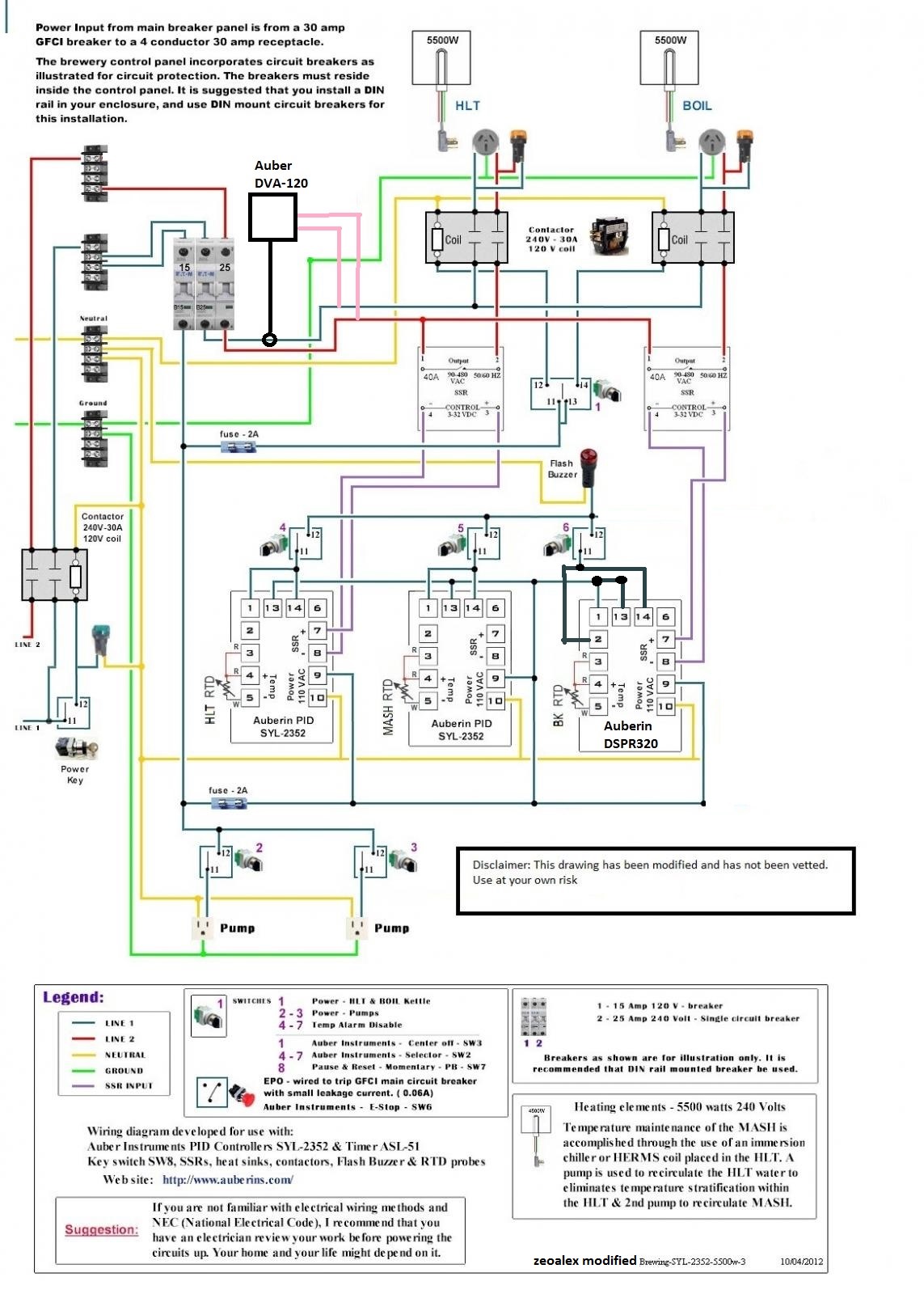
A few questions just to make sure my understanding of everything is correct:
Everything north of the SSR's (ie: Any wiring coming out of 25A fuses) should be 10AWG correct? since that sees 240V?
Everything south of the SSR's (anything coming out of the 15A fuse) can be 14AWG?
the SSR Input wiring can be 14AWG or smaller?
Thanks for the once-over! I'm excited to get this project moving!
 
Last edited:
Here's another design that is close to what you are looking for. The only items missing are the VA meter and the alarm buzzer/light and switches. It does feature a "safe start" interlock that prevents the main power contactor from closing if any of the pump or element switches are ON. I prefer to place the element contactors upstream of the element SSR's (unlike P-J) because SSR's typically fail in the ON mode, and the upstream contactors allow reliable removal of voltage from a failed SSR.

HERMS for Video.PNG


Brew on :mug:
 
good.jpg I just built a panel and used 10 AWG wire to power the heating elements and 14 AWG/18 AWG for everything else. It's the current that requires bigger wire, not the voltage. From what I found with online wiring calculators I could have used 12 AWG, but decided to go with 10 AWG. Each 5500 watt element can draw 23 amps when heating up water. You will find that larger wire is harder to work with around the small PID controllers.

I also installed a 60 AMP spa panel, this will allow me to run back to back batches. I used two EZboil DPSR320s and a SYL-2802B, one EZBoil for HLT and one for the boil kettle. The SYL-2802B allows me to see the temperature of water coming out of the mash tun and the temperature of the water after running through the herms coil. Also I recommend the riptide pumps, they are expensive but the built in valve and easy cleaning are hard to beat. Auber has a 16x12x8 box pre cut for three controllers and a heatsink for $100, if I did it again I would go that route, then all you have to do is drill the holes and paint. Auber has a nice label kit if you want labels, here is my finished panel. It was a fun build!
good.jpg
 
Last edited:
Here's another design that is close to what you are looking for. The only items missing are the VA meter and the alarm buzzer/light and switches. It does feature a "safe start" interlock that prevents the main power contactor from closing if any of the pump or element switches are ON. I prefer to place the element contactors upstream of the element SSR's (unlike P-J) because SSR's typically fail in the ON mode, and the upstream contactors allow reliable removal of voltage from a failed SSR.

View attachment 594280
Brew on :mug:
oh that's killer, I've been basically looking for that exact drawing. Thank you!! I really like the idea of that safe start interlock as well. An additional alarm buzzer shouldn't be too hard to add if I decide I want one.

Is there any sort of issue with not having any circuit breakers held within the panel? Or are those mostly unnecessary?


View attachment 594303 I just built a panel and used 10 AWG wire to power the heating elements and 14 AWG/18 AWG for everything else. It's the current that requires bigger wire, not the voltage. From what I found with online wiring calculators I could have used 12 AWG, but decided to go with 10 AWG. Each 5500 watt element can draw 23 amps when heating up water. You will find that larger wire is harder to work with around the small PID controllers.

I also installed a 60 AMP spa panel, this will allow me to run back to back batches. I used two EZboil DPSR320s and a SYL-2802B, one EZBoil for HLT and one for the boil kettle. The SYL-2802B allows me to see the temperature of water coming out of the mash tun and the temperature of the water after running through the herms coil. Also I recommend the riptide pumps, they are expensive but the built in valve and easy cleaning are hard to beat. Auber has a 16x12x8 box pre cut for three controllers and a heatsink for $100, if I did it again I would go that route, then all you have to do is drill the holes and paint. Auber has a nice label kit if you want labels, here is my finished panel. It was a fun build!View attachment 594303

Yeah, I think I only want to use 10AWG where it's entirely necessary, I imagine it's a real pain to use. Did you use THHN/THWN wire for that?

My goal is to use the MLT PID as a temp-gauge moreso than anything, and then a PID for the HLT element, and an EZboil for the BK. I ended up finding a YuCo IP66 panel for $50 on ebay, it'll be a bit more work to get it all setup, but for the price I really couldn't turn it down. That label kit may be a good call though, your panel looks awesome!
 
oh that's killer, I've been basically looking for that exact drawing. Thank you!! I really like the idea of that safe start interlock as well. An additional alarm buzzer shouldn't be too hard to add if I decide I want one.

Is there any sort of issue with not having any circuit breakers held within the panel? Or are those mostly unnecessary?

You are welcome. This design was put together for a previous request.

You only need fuses/breakers in the panel where wire diameters are reduced. The fuses/breakers prevent wires from overheating in over current situations (e.g. a short circuit.) Note that fuses are used when wire size drops from 10AWG to 16AWG for the pumps, and for the smaller wires used for control power.

Yeah, I think I only want to use 10AWG where it's entirely necessary, I imagine it's a real pain to use. Did you use THHN/THWN wire for that?

My goal is to use the MLT PID as a temp-gauge moreso than anything, and then a PID for the HLT element, and an EZboil for the BK. I ended up finding a YuCo IP66 panel for $50 on ebay, it'll be a bit more work to get it all setup, but for the price I really couldn't turn it down. That label kit may be a good call though, your panel looks awesome!
You really only need the 10AWG where you are carrying the current for the elements. You could use as low as 18AWG for the pumps (they only draw ~1.4A), and the PID and contactor coil power could use even finer wire.

Here's another design I did for a RIMS system that shows how to wire alarms to EZBoil 3x0 controllers.

DSPR300 2-Pump 240V  2 Vessel RIMS.PNG


Brew on :mug:
 
Yeah, I think I only want to use 10AWG where it's entirely necessary, I imagine it's a real pain to use. Did you use THHN/THWN wire for that?

I just went to Home Depot for wire, not sure if its THHN or THWN.
 
You are welcome. This design was put together for a previous request.

You only need fuses/breakers in the panel where wire diameters are reduced. The fuses/breakers prevent wires from overheating in over current situations (e.g. a short circuit.) Note that fuses are used when wire size drops from 10AWG to 16AWG for the pumps, and for the smaller wires used for control power.


You really only need the 10AWG where you are carrying the current for the elements. You could use as low as 18AWG for the pumps (they only draw ~1.4A), and the PID and contactor coil power could use even finer wire.

Here's another design I did for a RIMS system that shows how to wire alarms to EZBoil 3x0 controllers.

View attachment 594315

Brew on :mug:
Right, ok that makes sense, so in lieu of flip breakers, you've got in-line glass fuses which in theory should never blow. Makes sense.

oh awesome, thank you. I may try to throw an alarm in just because

Is the preferred method to branch wires off, via a big terminal block?

This may be a dumb question - but I assume a 220V indicator light will work just the same as a 240V indicator light? Just from looking around ebay and the link, most seem to be listed as 220V

Also, you're showing 120V contactors for the elements...should those be 240V? Or is it 120 since each leg on the contactor only sees 120V?

I just went to Home Depot for wire, not sure if its THHN or THWN.

Gotcha, ok. I only ask because I've seen a few people recommend the THWN since it's waterproof/resistant
 
Last edited:
Right, ok that makes sense, so in lieu of flip breakers, you've got in-line glass fuses which in theory should never blow. Makes sense.

oh awesome, thank you. I may try to throw an alarm in just because

Is the preferred method to branch wires off, via a big terminal block?

You can do either. Choice should be driven by wire layout and convenience. Most device terminals can easily accommodate two wires with spade or ring terminations. You should avoid the use of wire nuts or other splicing connections.

This may be a dumb question - but I assume a 220V indicator light will work just the same as a 240V indicator light? Just from looking around ebay and the link, most seem to be listed as 220V

Also, you're showing 120V contactors for the elements...should those be 240V? Or is it 120 since each leg on the contactor only sees 120V?

The 220V indicators should work. Most of the world works on electrical systems that are spec'ed between 220V and 240V.

It's the coils of the contactors that are rated at 120V, as they are wired between one of the hots and neutral. The high current contacts are rated higher than 240V.

Gotcha, ok. I only ask because I've seen a few people recommend the THWN since it's waterproof/resistant

If you have a water tight enclosure, then you don't need waterproof wire inside.

Brew on :mug:
 
You can do either. Choice should be driven by wire layout and convenience. Most device terminals can easily accommodate two wires with spade or ring terminations. You should avoid the use of wire nuts or other splicing connections.


The 220V indicators should work. Most of the world works on electrical systems that are spec'ed between 220V and 240V.

It's the coils of the contactors that are rated at 120V, as they are wired between one of the hots and neutral. The high current contacts are rated higher than 240V.


If you have a water tight enclosure, then you don't need waterproof wire inside.

Brew on :mug:

Alright awesome, I figure I may have one or two terminal blocks and then just do spade/ring terminals at devices...just wanted to be sure

ok great, again, that was my assumption but wanted to be totally sure

wonderful, I just bought my enclosure today since it was a great deal, got a IP66 16x16x8 YuCo enclosure for $50 on open box

thanks for all your help!
 
I used glass fuses for my panel. even used 30a fuses for the element power circuits. Never had an issue. The pids and timers and such all drew less than 1/2A collectively and do not need wire of any substantial size once fused... This saves a lot of headache. same with wire for coils to turn on relays and such. the only things that need the beefed up power are the real loads like the elements and as Doug mentioned the pumps need to be somewhere in the middle to be properly sized. (I use DC pumps so different story)
On my first panel in my avatar pic I just used inline automotive style fuse holder for the pid power like you would find on a car stereo.. the budget for that build was tiny though and I recycled a lot of what I had to keep the panel under $300 to build. I got impatient and did such a messy job on the wiring it sits in my closet waiting to be torn apart and components reused as I would never sell it to someone the way it is now.. total rats nest and trying to figure out whats what is a nightmare... Dont make that mistake. Trust me. It worked well for years but being the engineer type I always want to tinker and improve (which is Why I went to a software touchscreen setup)

Ive built a few more since then and now use brucontrol for more flexibility. I also now use din rail breakers and fuses for wiring convenience and to better organize things inside.
 
Last edited:
I used glass fuses for my panel. even used 30a fuses for the element power circuits. Never had an issue. The pids and timers and such all drew less than 1/2A collectively and do not need wire of any substantial size once fused... This saves a lot of headache. same with wire for coils to turn on relays and such. the only things that need the beefed up power are the real loads like the elements and as Doug mentioned the pumps need to be somewhere in the middle to be properly sized. (I use DC pumps so different story)
On my first panel in my avatar pic I just used inline automotive style fuse holder for the pid power like you would find on a car stereo.. the budget for that build was tiny though and I recycled a lot of what I had to keep the panel under $300 to build. I got impatient and did such a messy job on the wiring it sits in my closet waiting to be torn apart and components reused as I would never sell it to someone the way it is now.. total rats nest and trying to figure out whats what is a nightmare... Dont make that mistake. Trust me. It worked well for years but being the engineer type I always want to tinker and improve (which is Why I went to a software touchscreen setup)

Ive built a few more since then and now use brucontrol for more flexibility. I also now use din rail breakers and fuses for wiring convenience and to better organize things inside.

Yeah, I was going to get some of the slow-blow glass fuses for the PID's and relay inputs and whatnot so I could neck it down to smaller wire. I planned on using a terminal block to distribute the wiring into some of those smaller inline fuses, but I'm going to do my best to keep things pretty clean in the panel. I'm an engineer and messes of wires drive me nuts.
I'm trying to keep costs relatively low, by doing things like sourcing lights and switches and RTD's from ebay, got an open box YuCo enclosure for half price+. I did a bit of poking through your initial thread and was wondering: did you like those MyPIN PIDs? I was absolutely planning on buying an auber EZboil for the boil kettle, but was considering going for the MyPIN for MLT and HLT.
Also, I know you sourced some SSRs pretty inexpensively, as most of the aubers appear to be rebranded units. I know the Fotek units are pretty widely counterfeited, using components that aren't useful up to the 40A they're rated to, do you have any tips to avoid that? Or should I just go on and buy the auber units to make sure I'm getting something good?
I would go with the Berme or mager branded units.. I'm 99% sure thay are all made by MGR including aubers version although auber may have recently changed their supplier. I have never had a failure on the berme ones yet or seen reports of any. they are like $5... Ebay is the way to go for sure.. best place for RTD's too. My advice is to get the ones with the teflon cables and avoid the cheap stainless braided cable ones. they are junk and easily kink and short. The ezboil is nice but I had mixed feeling about it after upgrading one of my mypin td4 pids to it for my BK.. I did not find it intuitive to use but that might just have been me. It did seem to hold temps more precisely not that it matters for a BK.

I really like the mypin td4 pids... I found them easy to switch from pid to manual mode(unlike what ive read of the auber pids where people put in secondary knobs and switches to avoid this) and never had any quality issues. the 1 second cycle time was a plus too.
Yeah, I've had pretty good luck with ebay so far...I was going to get a few things from there still (SSR's and maybe PIDS specifically).

Sounds like maybe 2 TD4's and the EZ boil may be the best way to go for what I'm trying to do.
Thank you for the help!
 
I would go with the Berme or mager branded units.. I'm 99% sure thay are all made by MGR including aubers version although auber may have recently changed their supplier. I have never had a failure on the berme ones yet or seen reports of any. they are like $5... Ebay is the way to go for sure.. best place for RTD's too. My advice is to get the ones with the teflon cables and avoid the cheap stainless braided cable ones. they are junk and easily kink and short. The ezboil is nice but I had mixed feeling about it after upgrading one of my mypin td4 pids to it for my BK.. I did not find it intuitive to use but that might just have been me. It did seem to hold temps more precisely not that it matters for a BK.

I really like the mypin td4 pids... I found them easy to switch from pid to manual mode(unlike what ive read of the auber pids where people put in secondary knobs and switches to avoid this) and never had any quality issues. the 1 second cycle time was a plus too.
ok, so I've been doing some looking and it would appear that the mypin TA4-SNR is the most readily available. It looks like you end up using mostly TD4's?
My understanding is that the only real difference is that the TA4 doesn't have a manual mode (which shouldn't much matter for HLT/MLT?)
the -SNR model from my understanding means that it's SSR control, 1 alarm relay control?
Correct, I own both and have used both.. ta4 has no manual duty cycle mode but works fine otherwise.
 
Last edited by a moderator:
so I'm in the midst of putting my panel together now (finally)!
here's a stupid question for you guys who know better than I do. When I go ahead and mount all of my contactors, do I need to mount them with nylon screws and/or like washers? The mounting-board in my panel is unpainted, and when I pulled the mounting panel off of the contactor it looks like it rests right on part of the coil.

I just want to avoid energizing the whole board and zapping someone (or myself)

thanks!
 
Anything that sees a full 240v needs to be 10awg regardless of current whoever said that. It's not a matter of voltage or current its a matter of heat generation.
 
Anything that sees a full 240v needs to be 10awg regardless of current whoever said that. It's not a matter of voltage or current its a matter of heat generation.
oh absolutely and that's the plan. I'm using 10awg (stranded) for the 240V stuff, 14awg for pumps and 18awg for the coil and control wires
 
Contactors you can just mount to the board with whatever. Nothing to worry about using metal screws the brackets aren't
 
so I'm in the midst of putting my panel together now (finally)!
here's a stupid question for you guys who know better than I do. When I go ahead and mount all of my contactors, do I need to mount them with nylon screws and/or like washers? The mounting-board in my panel is unpainted, and when I pulled the mounting panel off of the contactor it looks like it rests right on part of the coil.

I just want to avoid energizing the whole board and zapping someone (or myself)

thanks!
It should be ok to ground the frame of the contactors, which will happen automatically if you mount the contactors to a bare metal back plate with metal screws/bolts. The metal enclosure and door should both be grounded with wires connected to either welded studs or thru bolts. Don't depend on the hinges to ground the door.

Brew on :mug:
 
Anything that sees a full 240v needs to be 10awg regardless of current whoever said that. It's not a matter of voltage or current its a matter of heat generation.
This is not correct. Heat generation depends on the current flowing thru the wire, and the resistance of the wire. P = I^2 * RW, where "P" is the power/heat (in watts) created in the wire, "I" is the current flowing thru the wire, and "RW" is the resistance of the wire. Smaller wire has higher resistance, so more heat for the same current. Supply voltage doesn't play into the heat generated in wiring since the current is determined primarily by the load resistance - RL, I = Vsupply / RL You only need 10AWG for currents higher than 20A and lower than 30A. Contactor coils, indicator lights, PID's, etc. have high impedances, so will draw much less than 1A at 240V.

Brew on :mug:
 
oh absolutely and that's the plan. I'm using 10awg (stranded) for the 240V stuff, 14awg for pumps and 18awg for the coil and control wires
You only need 10AWG for the wires that will carry the full element current. You can use finer wire for lower current 240V circuit branches, as long as the insulation on the wire is rated for 240V or more. Using finer wire for lower current branches will make your panel assembly go much easier.

Brew on :mug:
'

Awesome, and that;s how I'm going about it - 10AWG out of the input plug, to the coils/SSR in/out (not the coil), and that's about it really.

Hopefully one last question - I'm attempting to avoid use of any bus bars so I'm using the contractor spades, and doubling up on some of the screw terminals when necessary. Trouble I'm having is with the neutral wire. Based on the above diagram, I'm going neutral from the L14-30 (as a 10awg), using a quick disconnect down to a 14awg into the pump L6-30, jumping that to the other pump L6-30, and I will likely run from there up to the panel face via 18awg wire, and run that around the necessary switches/etc.

My fear is necking down that neutral wire without any fuse or anything like that, but my understanding is that it's safe because the neutral doesn't ever really see any major current - only when the two hots are out of phase (which won't much matter since all of the dual line branches don't have a neutral wire?)
Neutral never requires fusing, as it cannot supply current.

Brew on :mug:
 

Latest posts

Back
Top