CraftBeerPi - Raspberry Pi Software

Homebrew Talk - Beer, Wine, Mead, & Cider Brewing Discussion Forum

Help Support Homebrew Talk - Beer, Wine, Mead, & Cider Brewing Discussion Forum:

This site may earn a commission from merchant affiliate links, including eBay, Amazon, and others.
Hi everyone. I'm in the process of building my first pi electric brewery. I have experience with the standard PID's, etc and now am upgrading to the Pi. With that said, I'm still a novice at code writing. I want to put a cooling fan in my system and have it kick on at a certain temp. I can do this utilizing the cooling function in the fermentation part of CBPi, but would like a way to do it in the regular brewing section. Can anyone help me out?

Thanks
 
I'm putting together a terragady v5.0 board. Can someone tell me which direction the MP1584 goes on the board? It is symmetrical and I don't see any markings I recognize showing which way to orient it.

Thanks
 
Looking for some troubleshooting help. Got my terragady 5.0 board put together and fired up. I have two DS18B20 temp sensors up and working fine. I cannot however get my SSR to respond properly. It appears that all of the GPIO outputs have 12v on them from the moment the terragady board is put onto the PI.

Is there some configuration I am missing?

I have inspected all of the soldering and I don't see any obvious bridging between any connectors. I do seem to have continuity between the 12v input and the positive side of each GPIO. Any advice on how to troubleshoot something like this?

My best guess is that I may have bridged some solder underneath the female connector when I soldered the 40 pins onto the terragady board. They all look good from on top of the board, but I have the black plastic female side tight against the PCB. Is there any way to troubleshoot this without just unsoldering all 40 pins?

EDIT: I tested the continuity of the 40 pin connectors on the terragady board while it was disconnected from the pi. There was no continuity between any of the adjacent pins. Seems like that is not my problem?
 
Last edited:
Looking for some troubleshooting help. Got my terragady 5.0 board put together and fired up. I have two DS18B20 temp sensors up and working fine. I cannot however get my SSR to respond properly. It appears that all of the GPIO outputs have 12v on them from the moment the terragady board is put onto the PI.

Is there some configuration I am missing?

I have inspected all of the soldering and I don't see any obvious bridging between any connectors. I do seem to have continuity between the 12v input and the positive side of each GPIO. Any advice on how to troubleshoot something like this?

My best guess is that I may have bridged some solder underneath the female connector when I soldered the 40 pins onto the terragady board. They all look good from on top of the board, but I have the black plastic female side tight against the PCB. Is there any way to troubleshoot this without just unsoldering all 40 pins?

EDIT: I tested the continuity of the 40 pin connectors on the terragady board while it was disconnected from the pi. There was no continuity between any of the adjacent pins. Seems like that is not my problem?
did you adjust the MP1584 to 5v?
 
I am new to Craft Beer Pi and I got it installed and verified it was running via the command line command. However, when I try to access the interface I don't get anything. "The connection has timed out" Maybe there is something wrong with a port setting? Can the interface be accessed from the Rasberry Pi itself? If so, how? I know that the IP is correct because I was able to SSH into my raspberry pi.
 
I am new to Craft Beer Pi and I got it installed and verified it was running via the command line command. However, when I try to access the interface I don't get anything. "The connection has timed out" Maybe there is something wrong with a port setting? Can the interface be accessed from the Rasberry Pi itself? If so, how? I know that the IP is correct because I was able to SSH into my raspberry pi.

You might try un-installing and re-installing the software? Did you have it run on startup when you did the install configuration?

You can access the interface from the Pi, but you need to do it from the web browser. Just type in the same IP address and port 5000 like you would from any other computer.
 
I did, but only after hooking it up once when it was set to about 10v. The Pi wouldn't run so I troubleshot that and figured the v out. The Pi seems to be running just fine. I'm hoping I didn't kill something in my brand new Pi3.

I hooked my terragady board up to a different Pi last night. I got the same results. I did some more poking around on the board with a continuity meter. I have not yet found anything that seems out of place.

I do not know how to test the BC337's or the 1N4007 capacitors. The are all assembled in the correct orientation and the solder points look good. I also cannot detect any shorts in the input and output terminals. The MP1584 is supplied with 12v and is putting out 5.

Any help would be much appreciated.
 
I am new to Craft Beer Pi and I got it installed and verified it was running via the command line command. However, when I try to access the interface I don't get anything. "The connection has timed out" Maybe there is something wrong with a port setting? Can the interface be accessed from the Rasberry Pi itself? If so, how? I know that the IP is correct because I was able to SSH into my raspberry pi.

After installing CBPi, sometimes a dependency does not get installed correctly, thus halting the service from starting. You can check the status of the service by typing the following in a terminal.
Code:
sudo service craftbeerpiboot status
If it is not saying that the service is active, then type
Code:
cd ~/craftbeerpi3
sudo ./run.py

If at the bottom of the results, it says something along the lines of
ImportError: No module named flask_socketio
Then you will need to install the required PIP dependencies manually.

You will do that by typing
Code:
sudo pip install flask_socketio
Then trying
Code:
sudo ./run.py
and repeating for each missing module.

Once you get the service running, you're good to go.

If the PIP install says that it can't find the module to be installed, check the requirements.txt file for the module name. Keep in mind that it is case sensitive meaning that flask_GitPython isn't the same as flask_gitpython.
 
When I put in version 2.2 I had to do it 3 times to get it to work. Then when I went to 3.0, same thing -installed 3 times to get it to work. Every thing was done the same way each time.

It seams like it takes a few time for Rasberry to "like" it, lol

And make sure you are using the Master Branch version of 3.0
 
Looking for some troubleshooting help. Got my terragady 5.0 board put together and fired up. I have two DS18B20 temp sensors up and working fine. I cannot however get my SSR to respond properly. It appears that all of the GPIO outputs have 12v on them from the moment the terragady board is put onto the PI.

Is there some configuration I am missing?

I have inspected all of the soldering and I don't see any obvious bridging between any connectors. I do seem to have continuity between the 12v input and the positive side of each GPIO. Any advice on how to troubleshoot something like this?

My best guess is that I may have bridged some solder underneath the female connector when I soldered the 40 pins onto the terragady board. They all look good from on top of the board, but I have the black plastic female side tight against the PCB. Is there any way to troubleshoot this without just unsoldering all 40 pins?

EDIT: I tested the continuity of the 40 pin connectors on the terragady board while it was disconnected from the pi. There was no continuity between any of the adjacent pins. Seems like that is not my problem?
Since you already checked for continuity on the 40-pin header pins to the 12v input of the Terragady board, maybe there's a short elsewhere on the board? Or a diode or transistor in backwards? I am just guessing of things to try here - I'm far enough removed from my electronics training that I can't give definite things to try. I would not expect there to be continuity between the 12v input and each GPIO, since that would automatically trigger whatever they're connected to, right?

The only other definite thing I can suggest is because I've had to this time and again......triple and quadruple check everything on that Terragady board.

Thank you very much for the advice. I have already checked the orientation of the diodes. They all match the band on the graphic. The transistors are also all installed with the flat side oriented to match the graphic on the board. As I said, I'm not sure if there is a way to check those components with a multi-meter. I have checked all the resistors and they are on within a couple thousands.

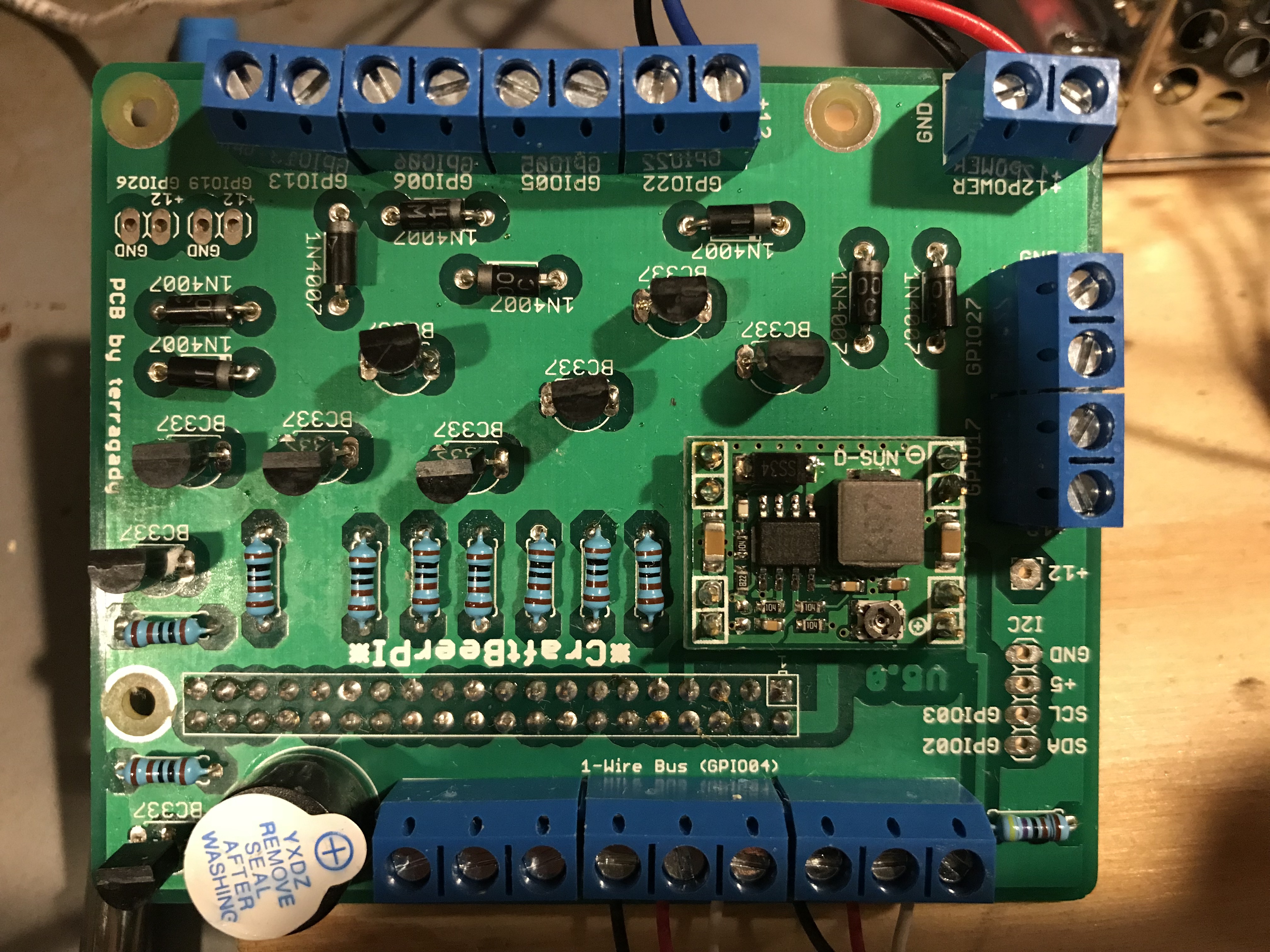
I'll poke around the board again and see if I can find any logic to where things might be shorted. If it is of any help here are pictures of the two sides of my board.

IMG_4202.JPG
IMG_4205.JPG
 
EDIT: I tested the continuity of the 40 pin connectors on the terragady board while it was disconnected from the pi. There was no continuity between any of the adjacent pins. Seems like that is not my problem?

Thank you very much for the advice. I have already checked the orientation of the diodes. They all match the band on the graphic. The transistors are also all installed with the flat side oriented to match the graphic on the board. As I said, I'm not sure if there is a way to check those components with a multi-meter. I have checked all the resistors and they are on within a couple thousands.

I'll poke around the board again and see if I can find any logic to where things might be shorted. If it is of any help here are pictures of the two sides of my board.

View attachment 554100 View attachment 554101
Just a thought - do you have the CraftbeerPi software GPIO outputs to INVERTED? I thought I once saw a checkbox for inverted outputs, but after looking at my CraftbeerPi v.3.0 GUI, I don't see where that was (if I really even saw it).
 
I’m still using 2.2. That setting is right on the device setup. It has no affect on my issue.

I’m thinking it’s got to be the board. The SSR goes powered as soon as I apply power to the breakout board. It doesn’t even need to be on the pi.
 
I’m still using 2.2. That setting is right on the device setup. It has no affect on my issue.

I’m thinking it’s got to be the board. The SSR goes powered as soon as I apply power to the breakout board. It doesn’t even need to be on the pi.
I have no other ideas.
I think it's time to break out the volt meter and start measuring voltages and troubleshooting.
 
I have no other ideas.
I think it's time to break out the volt meter and start measuring voltages and troubleshooting.

Thank you for the suggestions. I've already been poking around with a multi-meter. I will keep trying to see if I can figure out a pattern to things. I was hoping someone could tell me more about how to trouble shoot the board by using a multi-meter. I know only enough to get myself into trouble when it comes to this electronics stuff!
 
I'm fairly certain I had not crossed the polarity. I've taken it apart and put it together a few times now trying to figure it out. I'll make certain of it next time.

I know the SSR is activated because: The light goes on on the SSR, I had a fan plugged into it to deal with the known voltage leakage issue and the fan went on, my multi-meter shows 12v on the GPIO pin.

My next attempt is going to be trying moving the SSR to each of the GPIO positions and seeing if any of them work. I had tried GPIO5 and GPIO22, but not other ones. It seems from my multi-meter that some are automatically at 12v, others are at some very fraction of a volt.
 
Switch the dc leads going from the board to the ssr?

Great suggestion swimlan. I did try it, but that didn’t work. The SSR was just off.

But, I did figure it out!!!!!!

I mistakenly thought that using the “dummy” setup at the beginning was the way to set up the GPIO from scratch. When I went back and picked GPIO it worked!

I still have some setup to do, but things are working. :)

Thank you all for your help.
 
Victory was snatched from me today. :-(

I had the thing working perfectly. Was hoping to do a test with just water today. I was feeling pretty confident so I installed v3.0 on another card and installed that. I think something happened in pulling it apart and putting it back together. When I turned it on the buzzer started sounding. Then the PI died on me. I did some more troubleshooting with a multi-meter and couldn't find anything wrong, so I eventually tried it with a pi2 that I had. The buzzer went off again. I was able to disconnect the Terragady board and the Pi booted fine. Was wondering if it was the SSR malfunctioning and putting AC back into the PI. I disconnected that and tried again. This time it fried the second pi as well.

Perhaps I'm not cut out for this! lol

Not sure where I go from here.
 
Are you powering it from the terragady board? if so have you verified the little screw voltage adjuster on the MP1584 is set to 5V?

Other than that, the only things I can think of is they were plugged one pin off, or you have a solder bridge somewhere...
 
No list to my knowledge. I've tested chrome, chromium, edge, and Firefox. Didn't work in Firefox, but others it did.

Posted via my mobile tracking device


Yes, edge, FF, chrome work, however IE11 is a black screen on both win10 and win7, I have a nice older HP8510p that choked on win10, but runs great on win7 that I want to use, and load the fewest things possible on, I guess I will load chrome and try to turn as much of the evil stuff and cpu-demanding off as I can.
 
Are you powering it from the terragady board? if so have you verified the little screw voltage adjuster on the MP1584 is set to 5V?

Other than that, the only things I can think of is they were plugged one pin off, or you have a solder bridge somewhere...

In one of my earlier posts I indicated that I had done a pretty thorough examination of my soldering and could find no bridges.

I am powering from the Terragady. I have adjusted the voltage to 5v. I seem to have 5 volt where I need it and 12 volt where I need it. Something wrong happens when I connect it to the PI. It is possible that when I took it apart to put in the new SD card I re-assembled it one pin off, but I cannot figure out why the problem would persist even with a different pi. I'm struggling a little bit because I can't seem to test for the problem when it is not on the pi. Since I have some toasted pi's now I might just put it together and see if I can trouble shoot before something gets cooked.

I am using a LED lighting power supply and a cheap SSR. I actually scavenged these off of my homemade Arduino based unit I've been using for well over a year now. I wonder if I need to re-examine how I'm doing that? I can't imagine how the circuits would cross over unless the SSR has shorted out or something.
 
As indicated earlier, skip the add on board and try to get stuff working from the PI directly, one thing at a time. Adding a layer of complexity will just add room for errors. Once you get a handle on How It all works, put the add on board on.
 
As indicated earlier, skip the add on board and try to get stuff working from the PI directly, one thing at a time. Adding a layer of complexity will just add room for errors. Once you get a handle on How It all works, put the add on board on.

That is probably good advice. The sucky part is that it was working before it wasn't working.

I'm pretty familiar with the peripheral pieces as I built an arduino based controller from scratch. I have been working to verify their operation without the PI or board. I could get it all working without the board, and then connect the board and fry the PI again on the first try. What I need is to understand the board better and figure out how to trace whatever is causing my problem. I'm working on that as my next step.
 
I am still running my test mules off USB power, I have tuned the MP1584 on both, with a wall wort, but that was not a regulated supply, and feared it would vary a lot under load so going to wait to get a regulated one, just deciding wattage......
 
Unless you have some unique situation Where you need to have 12v relays, the add on board provides no benefit. There are scads of cheap 5v/10a opto isolated relays on ebay. I control March pumps and a chest freezer with them, straight from GPIO pins. Just get a beefy 5v PS.
 
I have a fairly complex setup (pumps, flo sensors, automated valves, and temp sensors) my problem is I have run out of gpio pins. How do I add more gpio pins, I have been looking at extension boards but I'm not sure. Is there one that is supported by cbpi? Any one you guys recommend?

Also side question, anyone know if the max31865(for rtd sensor) card is supported in 2.2 i have it working well in 3.0
 
anyone know where in the system I can tweak it to just have a single digit of temperature resolution, is more than sufficient, as goood as the accuracy, and easier to read in a hurry if you are scanning 8 temps on a screen with your eyes......

I don't see it in /home/pi/craftbeerpi3/modules/sensors/__init__.py , and I know the database stores it as higher res or somewhere else calculates it, but somewhere you should be able to say what the format is before being put on the screen...
 
Last edited:
I thought that might do it when it reads it and puts it in the db, which I guess is fine, was thinking to do it as it displays it...

So, to test, I changed:
`value.instance.read()`
to
`value.instance.read(round(),1)`

after reboot, I got all zeroes... I was pretty sure it would not work, as value.instance.read() does not return a value..

So I poked around the base modules, and thought maybe the one_wire might have it...


bingo... it is in:
/home/pi/craftbeerpi3/modules/base_plugins/one_wire/__init__.py

`
def read(self):
if self.get_config_parameter("unit", "C") == "C":
self.data_received(round(self.t.value + self.offset_value(), 2))
else:
self.data_received(round(9.0 / 5.0 * self.t.value + 32 + self.offset_value(), 2))
`
 
Unless you have some unique situation Where you need to have 12v relays, the add on board provides no benefit. There are scads of cheap 5v/10a opto isolated relays on ebay. I control March pumps and a chest freezer with them, straight from GPIO pins. Just get a beefy 5v PS.

I agree with you. Had I researched a little better I might have not gotten the terragady board. I mostly wanted it because it was an easy way to add all the screw terminals so my assembly would be clean.

As you might see from my previous posts, I’ve been having trouble with frying my PIs (would the plural be Pies???) last night I was able to isolate that it is the 12v side of the board that is causing problems. Things work fine when I use. 5v supple directly to the pi. It would be much simpler for me to just have a 5v system. My relays are already that so I’ve plugged them into the 5v GPIO that the terragady has on it.

When I get a chance I’m going to just turn my supply down to 5v and see if the whole board will run ok with that.
 
Back
Top