Controller for RIMS & Boil?

Homebrew Talk - Beer, Wine, Mead, & Cider Brewing Discussion Forum

Help Support Homebrew Talk - Beer, Wine, Mead, & Cider Brewing Discussion Forum:

This site may earn a commission from merchant affiliate links, including eBay, Amazon, and others.

Pintabone

Well-Known Member
Joined
Mar 9, 2017
Messages
162
Reaction score
19
Location
Easton
I've been doing some searching and am interested in the idea of possibly getting into a RIMS setup and also converting my boil kettle to electric. However, I don't see any prebuilt controllers available that have the ability to run both the RIMS element and a boil kettle element. This will allow the mash to run and recirculate with the RIMS element but also to heat up sparge water while the mash is running.

Does anyone have a setup like this? My current setup is 3 vessels with one propane burner. I like the idea of electric to not have to fill propane tanks and worry about the CO in the garage. Plus the temp control of RIMS is interesting.
 
If you're up for DIY, it's possible to build a panel that will control two elements at once.

Brew on :mug:
 
I just converted to all-electric. Same parameters as you--something to control the BK, something to control the RIMS.

I ended up DIY'ing an Auber panel, shown here: https://www.auberins.com/index.php?main_page=product_info&cPath=64_66&products_id=678 It starts at $370, that's about what I paid for it with the options I chose.

It allows for an EBiab setup, but I'm using it to control the boil and the pump.

But that's not RIMS. I added this from BobbyM at BrewHardware: https://www.brewhardware.com/product_p/tempcontrol_ipb16.htm

Those items don't include the elements, the RIMS tube, the cords. And your kettle will need a port or ports for the element.

Part of the reason I did it this way was that I could use 240v for the boil kettle, but 120v for the RIMS setup.

Maybe this will give you an idea of what you might want to do.

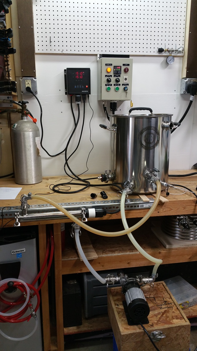
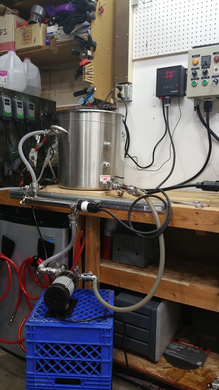
Here's how it looks set up:

conduit2.jpg
rimssetup.jpg
 
yes 50 amp's will run 2 elements up to 5500 watts each but in a rims you don't need one that big and no that EZboil wont run both at the same time, you need 2 and a 50 amp dedicated service for that to happen

In fairness, you just said you couldn't find any prebuilt controllers that could run a boil and a RIMS at the same time. I was merely pointing out that there are plenty of them. You didn't say until later that both elements have to run simultaneously off of the same PID. :) That's not possible AFAIK. Even the one-element-at-a-time panels have 2 or 3 PIDs.
 
In fairness, you just said you couldn't find any prebuilt controllers that could run a boil and a RIMS at the same time. I was merely pointing out that there are plenty of them. You didn't say until later that both elements have to run simultaneously off of the same PID. :) That's not possible AFAIK. Even the one-element-at-a-time panels have 2 or 3 PIDs.

I tried to explain I am looking for one panel to run the high watt element for the boil and also the low watt rims simultaneously. It’s becoming a bit more clear now that this may require two separate circuits or a 50a. The 50a option seems a bit much to run the low watt element.

Thanks Mongoose. I thought about this option but was hoping someone had a good resource to do something similar within one panel. My thought process was to do something like this to use 120 to run the RIMS. My electrical ability is very limited to typical household stuff but the DIY package you show above looks like something cool to try.

I do have a Spike 20 gallon kettle with TC ports. Would just need to add a port for the thermometer if needed. But I guess if using just for the boil kettle I shouldn’t need a thermowell.

Do you recirculate throughout the entire mash then and just leave the pump run since it’s separate from the RIMS controller?
You can run about 6500W of total heater power with a 30A circuit, and still be able to run up to 2 pumps. Any higher total power would require a 50A circuit. To get 6500W, both elements need to be 240V. You could for example run a 4500W element in the BK, and a 2000W element in the RIMS. Trying to run the low power element from 120V actually increases the total amps required.

You interested in seeing what such a control panel would look like?

Brew on :mug:

Definitely interested. I came across an older post from 2013 (I think that's when it was) that discussed the idea of running two lines in to the control panel. One was a 15a for the RIMS and then the other a 30a for the boil. I guess then having two PIDs in the control panel, each running from the separate power source.

Electric brewing is new to me in terms of the technical aspects of controlling it but I would like to eventually move to electric without getting into HERMS. So either just using a similar approach that I use now replacing the propane burner with an element and continuing with single infusion mashes or also adding a RIMS system to control mash temp.
 
I had a 40a breaker in my box for welders and my mill. I just ran another 8g line and use that same circuit for a 5500w boil element and 1650w rims tube. I run them at the same time (36amps). I saw the hassle and expense of 50a and 6g wire as overkill for something that sees intermittent duty.
 
You can run about 6500W of total heater power with a 30A circuit, and still be able to run up to 2 pumps. Any higher total power would require a 50A circuit. To get 6500W, both elements need to be 240V. You could for example run a 4500W element in the BK, and a 2000W element in the RIMS. Trying to run the low power element from 120V actually increases the total amps required.

You interested in seeing what such a control panel would look like?

Brew on :mug:
This is what I do, 5500w in my BK 4500w in my HLT and 1800w 240v element in my rims... using dc pumps. I run my HLT and rims element at the same time when heating the sparge water while recirculating my mash and running the panel and pump off the same power... 5 years and never a single issue with the power and my amp meter shows im always below 30amps.

A 5500w element draws 23 amps a 4500w element draws 18 amps peak... and a 2200w 240v element draws about 10 amps with an 1800w element at about 7 amps just to give you some numbers to play with.

this is where a 240v rims element makes more sense than 120v which draws twice the amp power than 240v for the same wattage. (for example if my 1800w rims was 120v it would draw 14 amps instead of the 7 it draws at 240v)

I'm actually running my 3bbl system at our brewpub off a similar model using less than 100 amp service, 2 2200w cartridge heaters in the 6ft rims and 4 5500w elements in my bk and 4 5500w elements in my HLT. using relays whenever my rims is active one of the 4 hlt elements is deactivated still keeping the max draw at below 100amps even though I have 120a feed on 2 seperate 60a circuits (isolated in the panel) Also using mainly small 24v td5 pumps since I love having the flow control for the rims and sparge.

On both my home brewing and brewpub rig I use simple mechanical relays to prevent allowing the BK and HLT elements from firing at the same time. (I have never found an instance where I would need them both on either)
 
Last edited:
I had a 40a breaker in my box for welders and my mill. I just ran another 8g line and use that same circuit for a 5500w boil element and 1650w rims tube. I run them at the same time (36amps). I saw the hassle and expense of 50a and 6g wire as overkill for something that sees intermittent duty.

Can you share info on your controller? I'm open to anything at this point. I like the idea of housing everything into one controller and I also like the idea of building something myself. Hopefully allowing me to learn something along the way.
 
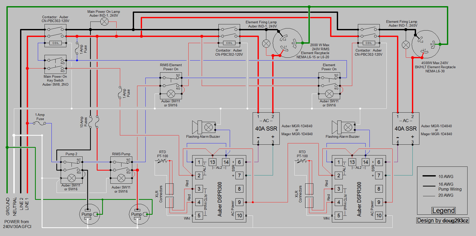
Here's a drawing I was having a hard time finding. Note that this design has a "safe start" feature that prevents main power from coming on if any of the pump or element switches are in the ON position. It also interlocks the RIMS pump to the RIMS power switch, so that the RIMS element cannot be powered on if the RIMS pump isn't on.

DSPR300 2-Pump 240V  2 Vessel RIMS.PNG


Brew on :mug:
 
Here's a drawing I was having a hard time finding. Note that this design has a "safe start" feature that prevents main power from coming on if any of the pump or element switches are in the ON position. It also interlocks the RIMS pump to the RIMS power switch, so that the RIMS element cannot be powered on if the RIMS pump isn't on.


Brew on :mug:

Thanks Doug, maybe i should have asked this prior to getting such a detailed diagram, but is there a good resource that explains the need for the various components within the panel?

To what Augie is saying above, would a panel based on this diagram be able to handle a lower W RIMS element and a 5500W boil element? In the end, it may be easier to do what Mongoose did above and just have two separate panels running off different circuits.
Have a look at this video that discusses this panel design. If you have additional questions, I can answer them. And yes, everything in there has a purpose.

A 5500W element uses 5500/240 = 22.9 A. You need to allow 2 A for the pumps (more if you run both from the same hot leg.) That would only leave 30 - (23 + 2) = 5 A for the RIMS element. 5 * 240 = 1200W. So, if you only need a 1200W element for the RIMS, you could use a 5500W kettle element simultaneously on a 30A circuit.

Brew on :mug:

Awesome will check it out tonight. I guess first quick question would be is there anything that would have to be different in the diagram if running off a 40A?

Also, those contactors, should they be 120v or 240v? When looking at some of that stuff on Auber it looked like there were two options for those.
 
Can you share info on your controller? I'm open to anything at this point. I like the idea of housing everything into one controller and I also like the idea of building something myself. Hopefully allowing me to learn something along the way.

Raspberry Pi repurposed from a media server, in $5 Lowes toolbox running Strange Brew Elsinore. 2 SSRs, one contactor, a 5amp 5v power supply, a big heat sink, and 4 5v relays from ebay. Around $175. Never made a wiring diagram, made it on a whim.
 
Awesome will check it out tonight. I guess first quick question would be is there anything that would have to be different in the diagram if running off a 40A?

Also, those contactors, should they be 120v or 240v? When looking at some of that stuff on Auber it looked like there were two options for those.
To change to 40A, the main power contactor (farthest left) should change from a "CN-PBC302-120V" to a "CN-PBC402-120V", and the 10AWG wire should be replaced with 8AWG wire. If you don't want to use 8AWG wire for all of the element branch wiring, you can add fuses/breakers where the element branches split to the kettle branches and RIMS branches. You can use 10AWG (protected by 30A fuses/breakers) or 12AWG (protected by 25A fuses/breakers) for the kettle element branches. You can use 14AWG wire (protected by 15A fuses/breakers) or 12AWG (protected by 20A fuses/breakers) for the RIMS branches.

The Auber contactor high current contacts are all rated up to 600V. The 120V in the contactor PN refers to the voltage needed by the control coil.

Brew on :mug:

So just change the one contactor and use 8AWG in place of 10. That seems easy enough. Is there any reason to use the thinner gauge wire and add in those fuses / breakers rather than change the wire?

And for the contactors, can you use these DIN rail mounted units? If so, instead of a 40A, would I have to get the 63A version available? Wondering if the DIN rail would make things easier to manage within a panel.

https://www.auberins.com/index.php?main_page=product_info&cPath=2_31&products_id=439
 
Last edited:
So just change the one contactor and use 8AWG in place of 10. That seems easy enough. Is there any reason to use the thinner gauge wire and add in those fuses / breakers rather than change the wire?

And for the contactors, can you use these DIN rail mounted units? If so, instead of a 40A, would I have to get the 63A version available? Wondering if the DIN rail would make things easier to manage within a panel.

https://www.auberins.com/index.php?main_page=product_info&cPath=2_31&products_id=439
There is nothing wrong with using wire that is heavier than necessary. Get some 8AWG wire and see how easy it is to bend and route inside a crowed enclosure. Many people find the heavy gauge wire difficult to work with, and prefer to use finer wire where the high current capacity isn't needed.

Yes you can use the DIN rail contactors (and other components.) It's perfectly fine to use components with higher current ratings than you need. Usually the only downside is the higher cost. The exception to this is fuses/breakers, which should never be rated for higher current than the max current rating of the wire runs they are protecting.

Brew on :mug:

Awesome thanks again. Sorry for all the questions but I'm really hooked on looking at all this stuff now. Couple more questions and I'll give it a break until I move forward and start purchasing some things:

Is it easier to use terminal strips to tie in all the neutral wires and various hot connections? If so, what do I have to look for there.

Do I need the alarm buzzers or if I want to leave those off is it as easy as just not hooking them up to the PIDs? Or is other wiring within the panel somehow tied into those alarm buzzer lights?
 
In some cases it will be easier to daisy chain connections, especially those on the door/front panel, to minimize the number of wires that have to pass between the front and back panels. The guide should be which option for any particular connection minimized wiring complexity and length. Make sure the terminal strips are rated for at least 250V and the screw terminals are big enough to handle the spades/eyelets that are appropriate for the wire size making the connection (crimp on terminals will specify the wires sizes they are good for on the packaging.)

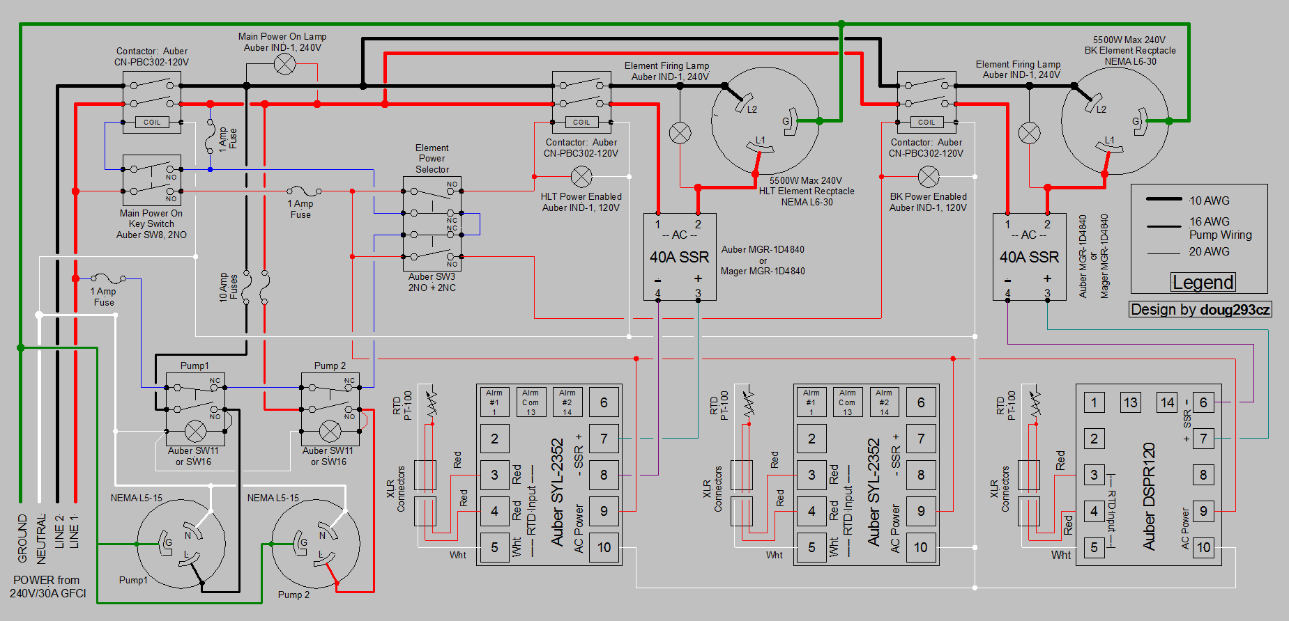
You don't need the buzzers or alarms. You can just leave out the wires that connect to them. Here's a different design that shows the wiring for an EZBoil DSPRxxx without alarms.

HERMS for Video.PNG


Brew on :mug:
 
In some cases it will be easier to daisy chain connections, especially those on the door/front panel, to minimize the number of wires that have to pass between the front and back panels. The guide should be which option for any particular connection minimized wiring complexity and length. Make sure the terminal strips are rated for at least 250V and the screw terminals are big enough to handle the spades/eyelets that are appropriate for the wire size making the connection (crimp on terminals will specify the wires sizes they are good for on the packaging.)

You don't need the buzzers or alarms. You can just leave out the wires that connect to them. Here's a different design that shows the wiring for an EZBoil DSPRxxx without alarms.

View attachment 594477

Brew on :mug:

So if I go with 40A, running a 5500W element for BK and get a 1650 120v element, I'm at about 37A. Plus less than 2A for the pump because I'll only be running one pump for awhile. I should be fine then right? Should I be looking for a low density watt element for the RIMS tube? Can you run a 120V low watt element off a 240V plug?
 
So if I go with 40A, running a 5500W element for BK and get a 1650 120v element, I'm at about 37A. Plus less than 2A for the pump because I'll only be running one pump for awhile. I should be fine then right? Should I be looking for a low density watt element for the RIMS tube? Can you run a 120V low watt element off a 240V plug?
why not get a 1650w 240v element? that gives you more flexibility and under 30a draw which might help should you choose to add something.

And yes the lower the wattage rims heater the less enzymes you will denature and less cleanup you will have this is why I use a 36" long 1800w element myself.
 
why not get a 1650w 240v element? that gives you more flexibility and under 30a draw which might help should you choose to add something.

And yes the lower the wattage rims heater the less enzymes you will denature and less cleanup you will have this is why I use a 36" long 1800w element myself.

I'm having a hard time finding one that is a low watt density at 240V and less than 2000w that's ready to connect to something. I was looking to use the elements that are welded onto a TC fitting to avoid dealing with any additional hardware and gaskets.
 
So if I go with 40A, running a 5500W element for BK and get a 1650 120v element, I'm at about 37A. Plus less than 2A for the pump because I'll only be running one pump for awhile. I should be fine then right? Should I be looking for a low density watt element for the RIMS tube? Can you run a 120V low watt element off a 240V plug?
Yes, this will work. The Brewhardware.com 1650 foldback element is listed as ULWD, so should be fine. The plugs/receptacles don't care what voltage they are actually carrying, so yes, you can use a L6-30 for the 120V element. Just make sure not to swap your cables between elements, as you will fry the 1650W element if you hook it up to the 5500W element cable. If you run your pump(s) from the hot line not used for the 120V element, then the pumps will not increase your total current draw at all (they will just shift current from the neutral to the hot line they are on)

Brew on :mug:

I guess that’s what I’m trying to confirm. Would the outlet and wiring for the 120v element have to be changed in the diagram then to drop to 120 within the panel? Or can you use a 120v element on a 240 v plug and it will still only use 120v and 1650 w? As you can see I’m showing my electric ignorance.
 
I guess that’s what I’m trying to confirm. Would the outlet and wiring for the 120v element have to be changed in the diagram then to drop to 120 within the panel? Or can you use a 120v element on a 240 v plug and it will still only use 120v and 1650 w? As you can see I’m showing my electric ignorance.
If the receptacle is connected to one hot line and neutral, then it will only supply 120V. On a switched 120V circuit, the switching has to be done on the hot line, not the neutral. The current thru the element is determined by the voltage applied and the resistance of the element according to Ohm's law:
V = I * R (V = voltage, I = current, R = resistance)
I = V / R​
The resistance of the element is fixed, so the controlling variable for the current is voltage. Power is given by:
W = I^2 * R = I * V = V^2 / R (W = watts of power)​

I can update the drawing for a 120V RIMS element if you like.

Brew on :mug:

If you don’t mind and it’s easy enough to do that’d be great.
 
If the receptacle is connected to one hot line and neutral, then it will only supply 120V. On a switched 120V circuit, the switching has to be done on the hot line, not the neutral. The current thru the element is determined by the voltage applied and the resistance of the element according to Ohm's law:
V = I * R (V = voltage, I = current, R = resistance)
I = V / R​
The resistance of the element is fixed, so the controlling variable for the current is voltage. Power is given by:
W = I^2 * R = I * V = V^2 / R (W = watts of power)​

I can update the drawing for a 120V RIMS element if you like.

Brew on :mug:

Ive been staring at this drawing for awhile and reading some stuff. Is it as easy as swapping the black load wire going into the rims contractor for a neutral? and continuing that through to the element receptacle? Will that still work the element lamp just after the contractor?
 
It's almost that easy. In addition to that, the pump that is powered by the red hot should be moved to the black hot for current balancing/minimizing purposes. In this case you don't need two 10A fuses. A single 10A fuse will be adequate for two pumps.

The neutral going to the RIMS element needs to be 14AWG for a 1650W element, and 12AWG for any higher.

Brew on :mug:

Thanks again Doug. So if I can confirm, the black hot going to the two pump switches should run through a single fuse, then I assume I can hit one pump switch from the other end of the fuse and then daisy chain off that connection to the next pump switch? Referencing back to your daisy chain recommendation.

And if I can confirm how to wire that RIMS element lamp, sorry for what is probably an elementary question but want to make sure I have this right. Just give it the hot off the SSR and a neutral?
 
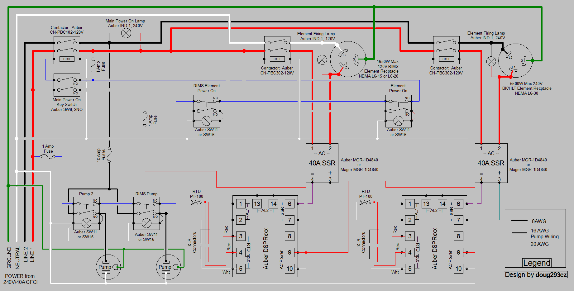
Ok, I updated the drawing for 40A and 120V RIMS element. I did not include the fuses/breakers that would be needed to reduce the element power wires from the 8AWG required for the incoming 40A. I think I accounted for everything else we talked about.

DSPR300 2-Pump 240V  2 Vessel RIMS 40A.PNG


Let me know if there is anything that looks flaky, or that you don't understand.

Brew on :mug:
 
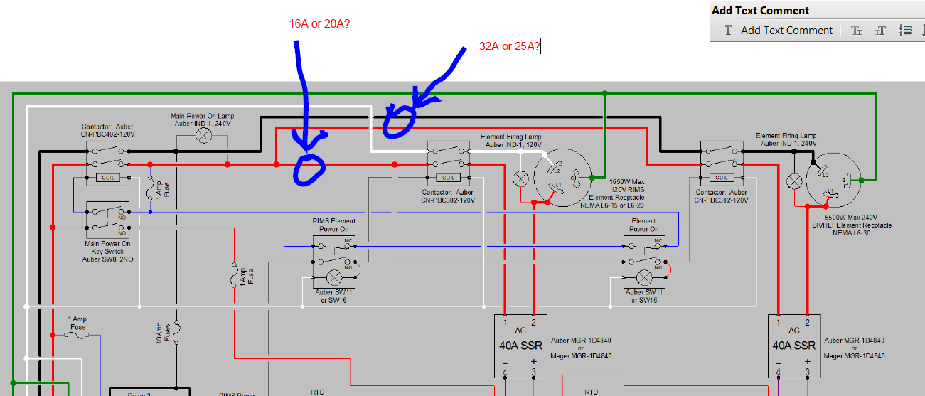
Alright, so maybe this will be the last question until I order all this stuff and move forward on putting it all together. If I want to add breakers, would I just put them where I've indicated in the picture? Use a 32A for the BK element and a 16A for the RIMS? Then I can step the wire down to the lower gauges you mentioned in a previous post? 25A breaker would allow me to use 12g wire to the BK element and a 16A breaker would allow 14g to RIMS element.

upload_2018-10-28_9-25-17.png
 
Alright, so maybe this will be the last question until I order all this stuff and move forward on putting it all together. If I want to add breakers, would I just put them where I've indicated in the picture? Use a 32A for the BK element and a 16A for the RIMS? Then I can step the wire down to the lower gauges you mentioned in a previous post? 25A breaker would allow me to use 12g wire to the BK element and a 16A breaker would allow 14g to RIMS element.

View attachment 595088
Correct. https://www.stayonline.com/product-resources/reference-circuit-ampacity.asp For the elements you have 2 current carrying conductors.

Brew on :mug:
 

Latest posts

Back
Top