BrunDog 50A eRig - no HLT for me!

Homebrew Talk - Beer, Wine, Mead, & Cider Brewing Discussion Forum

Help Support Homebrew Talk - Beer, Wine, Mead, & Cider Brewing Discussion Forum:

This site may earn a commission from merchant affiliate links, including eBay, Amazon, and others.
This is the secret! Thank you so much. I will try do it myself!

If it's not asking you so much, would you mind sharing a more detailed math calculations you do for your rig? Anyways, I can search it myself but would be a nice point of start for me!

Thanks!

Sorry... I overlooked this request. Here is a calculator I created for BruControl users. You should be able to get what you want from that: http://brucontrol.com/build/resources/

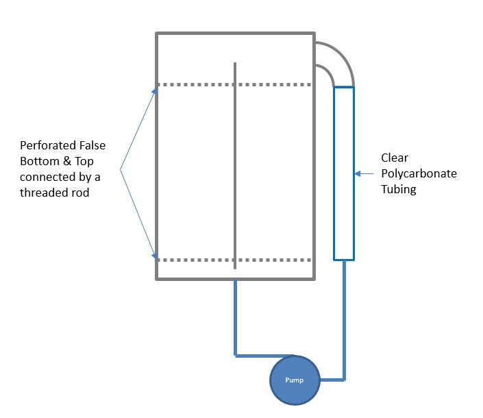
The short of it is that the vessel volume in quarts is: pi*(Dv/2)^2*Ha*0.017316, where Dv is the vessel internal diameter in inches and Ha is the height of the water in inches.

Let me know if you need more!
 
Super old post, sorry to bubble it up again. I read through some pages but couldn't find any details on your air pressure sensor setup.

I currently run eHERMS with BCS in bottom drain Keggles but I didn't bother with a sight glass. I'd like to skip that altogether but would like to introduce some type of volume measurements and your setup looks great... As I already have a T on the bottom of each of my keggles I'm invisioning swapping those out with a cross and putting a pressure sensor on the top part.

Do you have a parts list for the sensor components on your setup? Would the barometric pressure sensors on adafruit work?

Thanks and awesome setup!

Happy to help! One point of concern regarding changing the T to a cross and connecting the sensor airgap tube there... when liquid flows through the port, the pressure will drop (depending on the flow rate and relative restrictions) and causing invalid readings. The readings will normalize and be correct when the flow stops, so if you are using a pump you can turn it off and read the value then. But otherwise I recommend a unique bottom port - this is why I added discreet holes in my vessels.

Another caveat is that BCS cannot read analog values... my previous setup used an Arduino to read the sensor and report ON or OFF binary signals to the BCS. This was one of the reasons I created BruControl (shameless, shameless plug)!

The sensor I use is: https://www.digikey.com/product-detail/en/panasonic-electronic-components/ADP51B61/P17123-ND/3244557. This is a 6 kPa sensor, so will work for vessels that hold less than ~24 inches of liquid. Any more than that will over pressure the sensor. Also, with these low pressures (this is < 0.9 psi), the barb/tube fittings are acceptable. Much more than that, and positively clamped tubes may be needed. The last thing you want is a sprung leak of boiling wort!
 
Excellent! Thanks!

Yeah the initial thought was to use a tube and that pressure concern was the same in that case. It'd be helpful for ensuring volume at a particular time but will not be accurate when recirculating. Really do like your controller software and the use of a PC to run it all. Assuming a full panel built for a BCS controller, do you have rough cost estimates to do a drop in replacement without the cost of a PC included?

Well, the costs are not really significant. Here is my best estimate, removing the BCS and its 6V power supply, in rough $, not including optional mount items, like a screw shield, etc.

BC Basic: 99
Arduino MEGA: 15
12V power supply: 22
Thermistor interface board: 39
Total: 175

If you want to connect BC and the controller via network, then the cost increases about $80 for the Advanced version and for an Ethernet shield.
 
Thanks. And the advanced software is able to communicate with the Arudino Mega over it's associated Ethernet board rather than a local device (USB)?

So in theory I could use a VM to run the software and RDP / use the web server (future)?

Correct and correct. I currently use RDP very successfully over WiFI with a 1920 x 1080 screen. We are indeed working on the web interface.
 
Wicked setup Brundog. Can you give an update on your system.
I'm currently building a 3v herms full electric 30 gallon system
I have bought a bcs and will have 4 x 5500w elements.
Just thought if I only had 2 it would take forever to heat 100 litres to a boil.

Look forward to seeing how your setup has evolved.

Gav
 
Thanks. The control system change and addition of the BK level sensor were the last changes. I have been fine tuning the script a bit to work out some little bugs associated with automation. But it is running well! The next changes will be to incorporate some LODO: changed mash tun and a new chiller.

I agree 10kW is appropriate for 30 gallons. Good luck with your build!
 
Pretty cool Brundog, thoroughly enjoyed the thread & videos.
A little disappointed your dog didn't make a cameo appearance.
Anyway, thanks for sharing.
 
Hi Brundog,

Would you mind posting a link of your Propertioal valves please?
Also, would it be possible to run your controller without removing the BCS?

So just switch between both yours and BÇS?
Already have the 12v power supply and really like the idea of the proportional valves.
Thanks
 
My valves at KLD. I buy them straight from China.

The proportional valve is the KLD20T though there is no info online as these are custom made. Here is the valve type: http://www.electric-valve.com/20.html

PM me if you want one. I am putting a few in stock for BruControl users who want one without jumping through lots of hoops/headaches, but I am happy to offer to anyone interested.
 
Minor but sweet upgrade in my opinion... Snagged this gorgeous hp 21” touch monitor off eBay for a steal (2105tm). The monitor is mounted using a $20 monitor arm off one of the posts of my brewery cart.

I initially used a RPi as a front end to Remote Desktop into my BruControl server machine. It works fine but I found the RPi doesn’t support a touchscreen keyboard well. So I grabbed a $99 mini pc and I have to say... it works really well. It would run BruControl with plenty of headroom. I will just use it as an RDP client but suggest anyone can use it as the host for BC. It’s got the horsepower to run video apps well too, for when entertainment during brewing is in order, like watching my favorite YouTube channels!

View attachment IMG_1754.jpg
View attachment IMG_1753.jpg
View attachment IMG_1755.jpg
 
Minor change... originally I planned to mount a 10” touchscreen LCD panel in the pedestal enclosure. But since bigger is better, I went with the large touchscreen as shown above. So the pedestal isn’t needed. I moved these dedicated controls (key switch, E-stop, power LED, element on LEDs, and the alarm/LED) mounted into a smaller plastic enclosure, and mounted to the top span.
View attachment IMG_1775.jpg
 
Did you have to drill through the box? I've always avoided that if I can to be extra careful (some people use a word that starts with "a"...) about letting water into my electrical boxes.

I may have said before (or possibly given the impression ;)) that I am detail obsessed. One of the biggest challenges for me when designing an epic brewing stand is how to mount the various components. It's amazing how hard it can be to mount a weatherproof electrical box...those little tabs they come with aren't worth dealing with.
 
Yes, I have grown accustomed to your detail (and appreciate it!). Yes I drilled two holes, but they are fairly sealed. I could add some silicone around the holes but don't feel it necessary. With the location high up, it would be really unlikely water/wort would make it up there, let alone go sideways into the holes. I was thinking of doing a signal tower but still needed locations for the switch and E-stop, so went this route. This box is watertight and comes pre-drilled with 22mm holes. Got it on Amazon for $18: https://www.amazon.com/gp/product/B00GUTOOG6/
 
Last edited by a moderator:
I have been documenting my most recent addition/experiment here:

So not it’s time for my next experiment for potential upgrade: Reverse Flow Mash!

This has been done before, and is incorporated in certain systems like the Braumeister. But I want to take it to the next level and make it LODO friendly by incorporating an upside-down false bottom (aka false top) mounted to a mash cap. The idea is that the inbound liquid will flow up through the grain then flow back out through this false top. The mash cap/false top will float on top of the mash liquid. The possible benefits include: no stuck mash and unhindered recirculation flow rate, underletting the grain at the start (great for automation), taking advantage of heated liquid’s natural convective currents and LODO ready via underletting and a sealed top. The possible detriments include: poor wort clarity due to no true grain bed “filter”, inability to effectively sparge (because the wort will be more dense than sparge water, causing it to sink).

This will be a test, but I ultimately envision a center drain and a “telescoping” tube feed for that drain, which would allow the mash cap to rise and fall with liquid volume changes. For the test, I am using my sparge ring to feed the bottom and a hose to drain. More to come!
View attachment IMG_1804.jpg
 
Ya I will post up the concept drawings tmo.

Here is the result. Unfortunately it looks like this won’t work. I expected an efficiency hit and I sure got it. I also expected less clear wort and I got that too, but not as bad as I thought.

The real problem is during the latter stages in draining the MT, the grain holds the mash cap well above the liquid level, and the siphon to the pump transferring to the BK is lost. I had to push the cap down into the grain to get most of the liquid out to hit my volume target. But alas, despite my best effort, efficiency was way off. I was supposed to get 7 gals of pre-boil at 1.035 and got 1.027 by refractometer. Then at the end it was supposed to be 1.044 but it landed at 1.030. In fairness I boiled off a half gallon less than expected due to the spray condenser system, so that meant more volume than expected too.

This was also impossible to stir which I usually do once or twice early in the mash which makes me wonder if that affected efficiency. I doubt it as I was able to absolutely rip the recirc rate.

Initial runnings to BK. Not as clear as usual but not horrible.

View attachment IMG_1809.jpg

The dent in the mash made by pushin down hard on the cap:
View attachment IMG_1816.jpg

Much more true in the sample, though in fairness I drew it off the bottom of the fermenter pre-pitch.
View attachment IMG_1817.jpg
 
Nice experiment although I have to criticize you for breaking a cardinal rule of scientific experimentation: Never have multiple experiments running at the same time! It’s too hard to separate the different effects of each process variable.

Of course, since I really want to see the results of your steam condenser, I can’t complain too much! :D

I also wouldn’t call this a failure. You’ve identified a key factor for success: the mash lid needs some sort of locking mechanism to hold it down. Maybe a brace that uses pressure against the sidewalls of the tun to hold it down? Something like this: https://www.amazon.com/Camco-44063-Cupboard-Bars-pack/dp/B000EDUUHQ/ref=sr_1_8?s=hi&ie=UTF8&qid=1508414243&sr=1-8&keywords=spring+tension+rod

I use these in our RV fridge to keep everything from falling over while driving. Not very high tech, but inexpensive and could be used to verify the concept before investing in something more robust.
 
Last edited by a moderator:
I wonder if the process would be more conducive to us full volume biabers.

I notice that the nozzles on your lok line are mostly pointed toward the kettle wall, could you reorient them to all spray directly up into the mash? Would it make a difference?
 
Here is the concept drawing of the reverse mash flow tun. Not my best artwork but you get the gist.
Reverse Flow Mash.jpg
 
Nice experiment although I have to criticize you for breaking a cardinal rule of scientific experimentation: Never have multiple experiments running at the same time! It&#8217;s too hard to separate the different effects of each process variable.

Oh you are so right - and believe me I feel guilty. The reality is it will be impossible to know what contributed what. Let's see... Unproven recipe, steam condenser, reverse mash flow, automation script not setup for this system, etc. Ya, good luck!

Just for giggles, here is the recipe I used. This is all leftover grain I had laying around. The hops are the only spare package I could find. Oh, and the dry yeast expired a year ago (I only use liquid - just keep it for backup). Surprisingly the sample was tasty, so it may turn out alright!

BTW the mash efficiency was ~55%. In order for this to really work, the flow direction would need to be reversed, which would take some valve work that I am not sure is worth it.... will stew on this for a while and figure out next steps if any.

View attachment ReverseMashBastard.pdf
 
Did you have to drill through the box? I've always avoided that if I can to be extra careful (some people use a word that starts with "a"...) about letting water into my electrical boxes.

I may have said before (or possibly given the impression ;)) that I am detail obsessed. One of the biggest challenges for me when designing an epic brewing stand is how to mount the various components. It's amazing how hard it can be to mount a weatherproof electrical box...those little tabs they come with aren't worth dealing with.

I could understand wanting it to be waterproof it it was somewhere that water or wort could get in but its mounted up above? unless he has a poor ventilation setup (Which I know he doesnt ;) ) Its not too much of a concern as far as I can tell.
 
Here is the concept drawing of the reverse mash flow tun. Not my best artwork but you get the gist.
View attachment 417751

Seems like attaching the telescoping tube at the bottom would be difficult to do, especially if it comes loose during a mash.

You got me thinking about this; how about a false bottom and top connected together by a threaded rod? Your overflow could go out a side opening at the top; maybe a 2" tri-clover fitting attached to the side of the kettle using JB Weld...hmm...seems like I saw someone do that recently :p

The outflow tube would have to be a decent size and maybe transparent so you could monitor level and make sure you didn't suck it dry when starting recirculation. This would have the advantage of allowing sparging by reversing the suction and discharge lines. You could also easily re-prime the pump by pouring water into the top of the overflow tube.

Something like this:
 

Attachments

  • Reverse Mash.JPG
    Reverse Mash.JPG
    33.5 KB · Views: 117
Actually the telescoping tubes was easy. Compression fitting at bottom in middle, 5/8" SS tube in that, then 1/2" SS tube inserted into that. This provides a fairly wide range of movement before disengaging. But this would also yield the same problem I had yesterday... no way to get all the sweet wort out.

The overflow idea you have is interesting but a fixed overflow location would be very difficult to use with different batch sizes, grist ratios, etc. At the end of the day, reversing flow again would need to be accomplished.
 
I wonder if the process would be more conducive to us full volume biabers.

I notice that the nozzles on your lok line are mostly pointed toward the kettle wall, could you reorient them to all spray directly up into the mash? Would it make a difference?

No, there are some pointed out and some pointed in. This is my normal sparge ring that sits atop the mash and it works well.
 
I am not sure at this point there is value in pursuing this further for my system. If the mash needs to be re-reversed (made normal, that is) for sparging and draining, that would require 2x 3-way valves to accomplish. That is significant additional hardware & controls for a gain of being able to underlet and recirc at high flow rates. I don't think that is a legit tradeoff, especially since grain conditioning and proper crush results in very infrequent stuck sparge on my system.

Plus with automation via the script, my mash recirc rate is self-tuning... meaning that if the pressure starts to drop at the bottom, the flow rate is automatically reduced and vice versa. It tunes throughout the mash, starting slow and going faster as the mash progresses.

For LODO, I would use the same mash cap and attach my sparge ring to the bottom (the LODO guys do this now). That would make it easy to implement and keep the flow direction normal.

BTW, brewing with the 22" touchscreen right on the rig was HEAVEN!

On to the next experiment/upgrade! I don't know what that is just yet but suggestions are welcomed!
 
Good point. This is probably the way this should be done, but with the cap it would not be possible to stir the mash. No doubt it would improve efficiency though.

I think this method would be the dude if you could put a legit distribution filter/ring at the bottom and another at the top. Use these in place of a false bottom or false top. Mash recirc at very high flow rate. Then switch direction for mashout, sparging, and draining. This would need might be practical for those using manual hose switching.
 
I know I suggested switching direction for sparging, but as I think about it, why can’t you pump your sparge water in from the bottom? If you go at typical sparging rates, I don’t see why that wouldn’t work.
 
You did, and that would be the right thing to do. The problem with putting the sparge water on the bottom is you have to pull the wort off the top, which is fine during the sparge, but fails when you stop adding sparge water and begin to drain only. I suppose you could continue to sparge indefinitely but I have to believe efficiency would take a hit. Plus the cleanup is more of a PITA. Thought that might be good for LODO.

The other hypothetical problem with sparging water on the bottom is that water is less dense than the wort, so they may be inclined to switch places over a long sparge, hurting efficiency more.
 

Latest posts

Back
Top