BruControl: Brewery control & automation software

Homebrew Talk - Beer, Wine, Mead, & Cider Brewing Discussion Forum

Help Support Homebrew Talk - Beer, Wine, Mead, & Cider Brewing Discussion Forum:

This site may earn a commission from merchant affiliate links, including eBay, Amazon, and others.
You don’t need a ‘goto’ when the next line is the one noted by the goto.

Also is see values getting evaluated which will not, such as in State 1... Bain Marie comparison > 243 will never be executed because the Vapor temp lines before it will since its comparison values are lower. Make sense?

I would eschew the idea of state machines ala BCS which duplicate code to make your script efficient. Create one loop that runs and calls sections depending on the section.

1 - got it...

2 - yep, I see that, I was originally measuring two different temps, but when I change one to be the same as the other, I did not catch that, thank you.

3 - I tried to do one loop, but ran into some roadblocks

I have streamlined it here:

Code:
new value StopTemp
new string CurrentState

StopTemp = 207
stop "CoolDownTimer"
reset "CoolDownTimer"
restart "Total Runtime"

// Enable all devices needed
"9kW 0" Enabled = true
"9kW 1" Enabled = true
"9kW 2" Enabled = true
"9kW 3" Enabled = true
"Agitator" Enabled = true
"Bain Marie" Enabled = true
"Boiler Temp" Enabled = true
"Vapor Temp 1" Enabled = true
"Vapor Temp 2" Enabled = true
"PC Water IN" Enabled = true
"PC Water OUT" Enabled = true
"PC HX Return" Enabled = true
"RC Water IN" Enabled = true
"RC Water OUT" Enabled = true
"PC Pump" Enabled = true
"PC Fan" Enabled = true
"RC Pump" Enabled = true
"RC Fan" Enabled = true
"AlarmOut 1" Enabled = true
"Running" Enabled = true

// start the still run
"Running" State = on

[State0]
CurrentState = "Heat_36kW"
"9kW 0" State = on
sleep 1000     // pause before energizing another contactor
"9kW 1" State = on
sleep 1000     // pause before energizing another contactor
"9kW 2" State = on
sleep 1000     // pause before energizing another contactor
"9kW 3" State = on
sleep 1000     // pause before energizing Agitator
"Agitator" State = on

[State1]
if "Vapor Temp 1" Value >= 170 // exit to distilling state
 goto State5
endif
if "Bain Marie" Value < 240 // exit to State2 when BM temp reaches 240 (~1 Bar)
 goto State1
endif

[State2]
"9kW 3" State = off
CurrentState = "Heat_27kW"
if "Vapor Temp 1" Value >= 170 // exit to distilling state
 goto State5
endif
if "Bain Marie" Value < 241 // exit to State3 when BM temp reaches 241 (~1 Bar)
 goto State2
endif

[State3]
"9kW 2" State = off
CurrentState = "Heat_18kW"
if "Vapor Temp 1" Value >= 170 // exit to distilling state
 goto State5
endif
if "Bain Marie" Value < 241 // exit to State4 when BM temp reaches 241 (~1 Bar)
 goto State3
endif

[State4]
"9kW 1" State = off
CurrentState = "Heat_9kW"
if "Vapor Temp 1" Value >= 170 // exit to distilling state
 goto State5
endif
if "Bain Marie" Value >= 243 // shut off all heat if BM temp gets too high
 "Alarm 1" Active = true
 goto CoolDown
endif

[State5]
CurrentState = "Distill"
"PC Pump" State = on
"PC Fan" State = on
"RC Pump" State = on
"RC Fan" State = on

if "Vapor Temp 1" Value >= StopTemp // exit to cooldown state
 goto CoolDown
endif
if "Bain Marie" Value >= 243 // shut off all heat if BM temp gets too high
 "Alarm 1" Active = true
 goto CoolDown
endif
goto State5

[CoolDown]
CurrentState = "CoolDown"
"9kW 0" State = off
"9kW 1" State = off
"9kW 2" State = off
"9kW 3" State = off
restart "CoolDownTimer"
wait "CoolDownTimer" Value > 00:05:00 // waits until the timer exceeds 5 minutes

//Turn off Cooling
"PC Pump" State = off
"PC Fan" State = off
"RC Pump" State = off
"RC Fan" State = off
"Agitator" State = off

// Disable all outputs
"9kW 0" Enabled = false
"9kW 1" Enabled = false
"9kW 2" Enabled = false
"9kW 3" Enabled = false
"Agitator" Enabled = false
"PC Pump" Enabled = false
"PC Fan" Enabled = false
"RC Pump" Enabled = false
"RC Fan" Enabled = false
"AlarmOut 1" Enabled = false
"Running" Enabled = false

stop "Still Run Script"
 
Correct.
PC 1: Mini flashes, but no network config. Mini Lite flashes, but no network config.
PC 2: Mini flashes, network config worked. Mini Lite flashes, but no network config.

I have used both PCs to flash a simple blink program to the Lite, and the led then blinks as programmed, so I know the computers are talking to it. I figured screen shots wouldn't be helpful, as all it shows is it not doing anything, so here is a video. This is the flashing and failure of the network config on the Mini Lite. We can also do a GoTo if you'd like.


That is exactly what I am seeing on the MEGA 2560 v43 "ER" firmware as well.
 
Correct.
PC 1: Mini flashes, but no network config. Mini Lite flashes, but no network config.
PC 2: Mini flashes, network config worked. Mini Lite flashes, but no network config.

I have used both PCs to flash a simple blink program to the Lite, and the led then blinks as programmed, so I know the computers are talking to it. I figured screen shots wouldn't be helpful, as all it shows is it not doing anything, so here is a video. This is the flashing and failure of the network config on the Mini Lite. We can also do a GoTo if you'd like.


Try resetting the D1 after flashing it (before connecting via Termite). Also, try sending just a semi-colon, then wait a long time for a response. Don't send it multiple times.
 
I gave it a try and no difference. I flashed the MEGA 2560, power cycled the board, went into network setup and termite still has no response with a ; instruction after 2-3 minutes.

Update: ...or after several hours. It just sits there.
 
Last edited:
I gave it a try and no difference. I flashed the MEGA 2560, power cycled the board, went into network setup and termite still has no response with a ; instruction after 2-3 minutes.

Update: ...or after several hours. It just sits there.
Same story here. Let it sit for 30 minutes while I was doing other things. No response.
 
Ok. What you linked is the lite version... it is ESP8285 based, not ESP8266 and has 1M of flash, not 4M like the D1 I have tested. Not sure this should matter but the firmware for the D1 is for ESP8266 / 4M. Let me research further.
 
Try the Sonoff TH10/16 firmware v43. The I/O won’t line up but that device is 8285 based. See if that works and gets a response in the network setup.

Sorry, the problem with the ESP world is the varied implementations of different builders. It’s very difficult to target them all. Going forward we will make more “universal” versions and let you use the I/O which is actually available.
 
1 - got it...

2 - yep, I see that, I was originally measuring two different temps, but when I change one to be the same as the other, I did not catch that, thank you.

3 - I tried to do one loop, but ran into some roadblocks

I have streamlined it here:

Code:
new value StopTemp
new string CurrentState

StopTemp = 207
stop "CoolDownTimer"
reset "CoolDownTimer"
restart "Total Runtime"

// Enable all devices needed
"9kW 0" Enabled = true
"9kW 1" Enabled = true
"9kW 2" Enabled = true
"9kW 3" Enabled = true
"Agitator" Enabled = true
"Bain Marie" Enabled = true
"Boiler Temp" Enabled = true
"Vapor Temp 1" Enabled = true
"Vapor Temp 2" Enabled = true
"PC Water IN" Enabled = true
"PC Water OUT" Enabled = true
"PC HX Return" Enabled = true
"RC Water IN" Enabled = true
"RC Water OUT" Enabled = true
"PC Pump" Enabled = true
"PC Fan" Enabled = true
"RC Pump" Enabled = true
"RC Fan" Enabled = true
"AlarmOut 1" Enabled = true
"Running" Enabled = true

// start the still run
"Running" State = on

[State0]
CurrentState = "Heat_36kW"
"9kW 0" State = on
sleep 1000     // pause before energizing another contactor
"9kW 1" State = on
sleep 1000     // pause before energizing another contactor
"9kW 2" State = on
sleep 1000     // pause before energizing another contactor
"9kW 3" State = on
sleep 1000     // pause before energizing Agitator
"Agitator" State = on

[State1]
if "Vapor Temp 1" Value >= 170 // exit to distilling state
 goto State5
endif
if "Bain Marie" Value < 240 // exit to State2 when BM temp reaches 240 (~1 Bar)
 goto State1
endif

[State2]
"9kW 3" State = off
CurrentState = "Heat_27kW"
if "Vapor Temp 1" Value >= 170 // exit to distilling state
 goto State5
endif
if "Bain Marie" Value < 241 // exit to State3 when BM temp reaches 241 (~1 Bar)
 goto State2
endif

[State3]
"9kW 2" State = off
CurrentState = "Heat_18kW"
if "Vapor Temp 1" Value >= 170 // exit to distilling state
 goto State5
endif
if "Bain Marie" Value < 241 // exit to State4 when BM temp reaches 241 (~1 Bar)
 goto State3
endif

[State4]
"9kW 1" State = off
CurrentState = "Heat_9kW"
if "Vapor Temp 1" Value >= 170 // exit to distilling state
 goto State5
endif
if "Bain Marie" Value >= 243 // shut off all heat if BM temp gets too high
 "Alarm 1" Active = true
 goto CoolDown
endif

[State5]
CurrentState = "Distill"
"PC Pump" State = on
"PC Fan" State = on
"RC Pump" State = on
"RC Fan" State = on

if "Vapor Temp 1" Value >= StopTemp // exit to cooldown state
 goto CoolDown
endif
if "Bain Marie" Value >= 243 // shut off all heat if BM temp gets too high
 "Alarm 1" Active = true
 goto CoolDown
endif
goto State5

[CoolDown]
CurrentState = "CoolDown"
"9kW 0" State = off
"9kW 1" State = off
"9kW 2" State = off
"9kW 3" State = off
restart "CoolDownTimer"
wait "CoolDownTimer" Value > 00:05:00 // waits until the timer exceeds 5 minutes

//Turn off Cooling
"PC Pump" State = off
"PC Fan" State = off
"RC Pump" State = off
"RC Fan" State = off
"Agitator" State = off

// Disable all outputs
"9kW 0" Enabled = false
"9kW 1" Enabled = false
"9kW 2" Enabled = false
"9kW 3" Enabled = false
"Agitator" Enabled = false
"PC Pump" Enabled = false
"PC Fan" Enabled = false
"RC Pump" Enabled = false
"RC Fan" Enabled = false
"AlarmOut 1" Enabled = false
"Running" Enabled = false

stop "Still Run Script"
I would add a small delay in each state loop to prevent each from occurring full CPU speed (likely doesn't need to be close to real time). Otherwise, from a syntax/flow perspective... it looks good. Do a dry run and see if it executes - or pause it and go step by step.
 
Same story here. Let it sit for 30 minutes while I was doing other things. No response.

Now your situation is different - you are using known hardware. Trying to remember how you got here... did you get the pre-built MEGA from us? If not, please post up the specific hardware you are using and give me a quick rundown of the steps you have taken so far, and if it has every worked correctly.
 
Try the Sonoff TH10/16 firmware v43. The I/O won’t line up but that device is 8285 based. See if that works and gets a response in the network setup.

Sorry, the problem with the ESP world is the varied implementations of different builders. It’s very difficult to target them all. Going forward we will make more “universal” versions and let you use the I/O which is actually available.

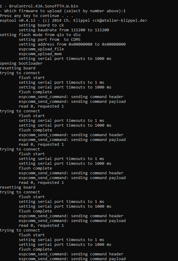
Still not working. Just acts like it can't connect to flash it.

upload_2018-11-28_11-51-2.png


I then used NodeMCU flasher to flash the Sonoff firmware to it, and it then flashed, but still no network setup. You've given enough of an effort for me, I'll get some of the appropriate boards. I was just trying to use the ones I had, but I'm sure I can find another use for them later.
 
I can comment on my scenario which is with the MEGA 2560, with ethernet and RTD. The setup process involves running the "InterfaceSetup.bat" that is part of the BruControl firmware (v43). This opens the command window where you can install the firmware or proceed to network setup or exit (options 1, 2, and 3 respectively). In my case and from what I can tell, phreaky's case, we can both successfully install the firmware but once that is complete and you then go to network setup and properly select the com port and so on, the terminal opens. This terminal is the Termite program and when you issue the %0&15; instruction there is no response in the terminal window. In my case, I was able to get a responses at this point 3-4 times over a period of 8 hours while I played with different settings and static IP addresses. Since that time and while nothing changed on the computer connected via USB to the MEGA 2560, the terminal window stopped producing responses (i.e. no count down timer, etc.).

I have since reflashed the firmware numerous times on different computers, running different versions of windows, with various USB drivers all resulting in nothing but no response from the terminal window.

It is worth noting that when flashed with the "serial" version of the firmware and connected via the serial connection to the BruControl HMI computer, everything works fine. It is just that the ethernet shield cannot be setup due to the lack of any response from the controller as viewed in the terminal (termite).
I ran into the issue where a mega would not respond to the %0&15 command. I found that I was copy and pasting the text into the terminal and that did not work. Typing it in 1 character at a time fixed it for me.
 
I ran into the issue where a mega would not respond to the %0&15 command. I found that I was copy and pasting the text into the terminal and that did not work. Typing it in 1 character at a time fixed it for me.

I’ll have to try/confirm. I don’t think I ever Copy/Pasted. Thanks for the FYI. Also... don’t forget the semi-colon!
 
Now your situation is different - you are using known hardware. Trying to remember how you got here... did you get the pre-built MEGA from us? If not, please post up the specific hardware you are using and give me a quick rundown of the steps you have taken so far, and if it has every worked correctly.

Yes I did get the MEGA 2560 from you (as well as the ethernet shield, screw shield, etc.). I am following the instructions in the manual and have had success with flashing and setting up the networking in the past. That being said, once it stopped responding, it has been unresponsive in the network setup portion of the process 100% of the time. This includes in scenarios I mentioned previously. That is, with two copies of the same ethernet shield, three different computers, two different versions of Windows and all sorts of usb drivers. I to just up arrow to get the %0&15; command in termite but I have also typed in directly with no improvement. Basically the only thing I haven't done is replace the MEGA 2560, mostly because it works fine via the serial connection.
 
Last edited:
You can ship it back and we’ll get it going again if you like.

Well I could do that but I kind of need to be able to make changes to the network settings in the future without sending the controller back and it might cost just as much to send it back as it would to get a new one from Amazon.

Is this an appropriate item if I was to decide to just get a new one?

http://a.co/d/iTIGOiG

I can use serial if this continues to not work out for my situation for whatever reason. If the card has gone belly up in some fashion that isn't on you, I may have static shocked it or something, who knows.

Yes, that’s a match.

Ok, LMK how to help.
 
So interesting enough, I have a Elegoo Mega2560 here that won't respond to Termite as well. It will flash just fine, however no response in Termite. When I enter the command, I can see the RX light flash on the mega, but it never tx's back. I have another board right next it, and using the same computer, cable, program instance (different port of course, but port 8, if thats any way common, to @VacationLand), no issues whatsoever. Infact I have about 5 boards here and only this one new out of the box has this issue. Things that make you go hmmmm.

edit tried E and F firmwares.
 
The keys are isolation and suppression. Proper grounding into a STAR pattern matters too to eliminate ground loops.

1. Separate high and low voltage wires. Eliminate loops where possible - they act as antennas.
2. Use shielded wire, with the shield tied to ground at the enclosure side only. Or use twisted wire - this reduces antenna affect.
3. Use solid state or electric switches (relays, e.g. SSRs or MOSFETs) over electromechanical ones (cube relays) where possible. For inductive loads, for DC circuits, use reverse-biased diodes (e.g. 1N4007) and for AC circuits use MOVs (Metal Oxide Varistors) and/or snubbers (R-C network).

For the MOVs, we have tested these with good success. Anything for 120V will likely work though: https://www.digikey.com/product-det...onic-components/ERZ-E14A201/P15585-ND/3694124
BrunDog,

I bought several of those MOVs from DigiKey to proactively address any voltage spikes caused by inductive-load switching. In the EMI diagram on the BruControl website, you show installation of the MOVs either parallel to the inductive load or across the switching contacts. Is either one superior to the other? In my case, it'll be much easier to put the MOVs across the contacts of the relays rather than parallel to the load (at least for my DPST contactors).

Thanks!
 
Odd. I have used Elegoo’s without issue. The hardware is based on the reference design so it shouldn’t matter.

One idea to throw out there that might help us debug this... We initially wrote the FW to flash the LED at either boot up or permanently, to provide visual indication the micro was processing data (indicating power was ok and it was properly running). Overheats, electrical noise, or bad code (don’t think so but anything is possible) can cause freeze-ups. With a blinking LED, this would be uncovered. We ultimately removed the boot-up LED flashing since the LED pin is available for a user to connect to hardware.

There is a workaround though: the “auto-startup” now built into firmware could be leveraged to duplicate this. You would set up a duty cycle on the LED pin, to set it blinking. Submit the store control code, then each power-up or reset will set it blinking. In this case, it would help let you know if the lack of serial response is because of frozen code or a serial issue.

Another thing that would help, for anyone willing, would be to send us your board so we can try to debug it. We can pay for shipping and the board cost.
 
BrunDog,

I bought several of those MOVs from DigiKey to proactively address any voltage spikes caused by inductive-load switching. In the EMI diagram on the BruControl website, you show installation of the MOVs either parallel to the inductive load or across the switching contacts. Is either one superior to the other? In my case, it'll be much easier to put the MOVs across the contacts of the relays rather than parallel to the load (at least for my DPST contactors).

Thanks!

Across the load, as close to the load is best, but let’s be practical. Try across the coil first and see if that makes a difference. If it does, then[emoji106], otherwise go across the power lines in the enclosure and see if that helps.
 
I am not seeing any results searching 'autostart' or 'auto start' in this thread, and I wanted a bootloader script to run on bootup of BruControl to allow me to start the process with a button and safety interlock switch.. (right now they are software switch and software button, but will do a momentary key switch and a momentary button on digital inputs)

it works, asking for peer review of code

bootup script: (autostart ON)
Code:
[initialize]

// ensure script is stopped on powerup
stop "Run Script"
// ensure software safety interlock switch is off
"Switch 1" State = false
[start]
// ensure button is off - had issue without this line
"Start Button" State = false
sleep 1000
if "Switch 1" State == true
 if "Start Button" State == true
  "Switch 1" State = false //reset the switch so start button is no longer active
  start "Run Script"
 endif
endif
goto start
 
Last edited:
a little video of my draft setup.. I need to work on the placement of the sleep commands so that the start/continue button is more responsive, but it looks to be working...


Code:
new value StopTemp
new string CurrentState

StopTemp = 207
stop "CoolDownTimer"
reset "CoolDownTimer"
restart "Total Runtime"
"Stop Still Run" State = false

// Enable all devices needed
"9kW 0" Enabled = true
"9kW 1" Enabled = true
"9kW 2" Enabled = true
"9kW 3" Enabled = true
"Agitator" Enabled = true
"Bain Marie" Enabled = true
"Boiler Temp" Enabled = true
"Vapor Temp 1" Enabled = true
"Vapor Temp 2" Enabled = true
"PC Water IN" Enabled = true
"PC Water OUT" Enabled = true
"PC HX Return" Enabled = true
"RC Water IN" Enabled = true
"RC Water OUT" Enabled = true
"PC Pump" Enabled = true
"PC Fan" Enabled = true
"RC Pump" Enabled = true
"RC Fan" Enabled = true
"AlarmOut 1" Enabled = true
"Running" Enabled = true

// start the still run
"Running" State = on

[State0]
CurrentState = "Heat_36kW"
"9kW 0" State = on
sleep 1000     // pause before energizing another contactor
"9kW 1" State = on
sleep 1000     // pause before energizing another contactor
"9kW 2" State = on
sleep 1000     // pause before energizing another contactor
"9kW 3" State = on
sleep 1000     // pause before energizing Agitator
"Agitator" State = on

[State1]
if "Vapor Temp 1" Value >= 170 // exit to distilling state
 goto State5
endif
if "Stop Still Run" State == true
 goto CoolDown
endif
if "Start Still Run" State == true
 sleep 500
 goto State2
endif
if "Bain Marie" Value < 240 // exit to State2 when BM temp reaches 240 (~1 Bar)
 sleep 500
 goto State1
endif

[State2]
"9kW 3" State = off
CurrentState = "Heat_27kW"
if "Vapor Temp 1" Value >= 170 // exit to distilling state
 goto State5
endif
if "Stop Still Run" State == true
 goto CoolDown
endif
if "Start Still Run" State == true
 sleep 500
 goto State3
endif
if "Bain Marie" Value < 241 // exit to State3 when BM temp reaches 241 (~1 Bar)
 sleep 500
 goto State2
endif

[State3]
"9kW 2" State = off
CurrentState = "Heat_18kW"
if "Vapor Temp 1" Value >= 170 // exit to distilling state
 goto State5
endif
if "Stop Still Run" State == true
 goto CoolDown
endif
if "Start Still Run" State == true
 sleep 500
 goto State4
endif
if "Bain Marie" Value < 242 // exit to State4 when BM temp reaches 242 (~1 Bar)
 sleep 500
 goto State3
endif

[State4]
"9kW 1" State = off
CurrentState = "Heat_9kW"
if "Vapor Temp 1" Value >= 170 // exit to distilling state
 goto State5
endif
if "Bain Marie" Value >= 244 // shut off all heat if BM temp gets too high
 "Alarm 1" Active = true
 goto CoolDown
endif
if "Stop Still Run" State == true
 goto CoolDown
endif
if "Start Still Run" State == true
 sleep 500
 goto State5
endif
 sleep 500
goto State4

[State5]
CurrentState = "Distill"
"PC Pump" State = on
"PC Fan" State = on
"RC Pump" State = on
"RC Fan" State = on
"PID 1" Enabled = true

if "Vapor Temp 1" Value >= StopTemp // exit to cooldown state
 goto CoolDown
endif
if "Bain Marie" Value >= 243 // shut off all heat if BM temp gets too high
 "Alarm 1" Active = true
 goto CoolDown
endif
if "Start Still Run" State == true
 sleep 500
 goto CoolDown
endif
sleep 500
goto State5

[CoolDown]
CurrentState = "CoolDown"
"9kW 0" State = off
"9kW 1" State = off
"9kW 2" State = off
"9kW 3" State = off
restart "CoolDownTimer"
wait "CoolDownTimer" Value > 00:00:05 // waits until the timer exceeds 5 minutes

//Turn off Cooling
[PowerDown]
"PC Pump" State = off
"PC Fan" State = off
"RC Pump" State = off
"RC Fan" State = off
"Agitator" State = off
stop "Total Runtime"

// Disable all outputs
"9kW 0" State = off
"9kW 1" State = off
"9kW 2" State = off
"9kW 3" State = off
"9kW 0" Enabled = false
"9kW 1" Enabled = false
"9kW 2" Enabled = false
"9kW 3" Enabled = false
"Agitator" Enabled = false
"PC Pump" Enabled = false
"PC Fan" Enabled = false
"RC Pump" Enabled = false
"RC Fan" Enabled = false
"PID 1" Enabled = false
"AlarmOut 1" Enabled = false
"Running" Enabled = false

stop "Still Run Script"
 
So interesting enough, I have a Elegoo Mega2560 here that won't respond to Termite as well. It will flash just fine, however no response in Termite. When I enter the command, I can see the RX light flash on the mega, but it never tx's back. I have another board right next it, and using the same computer, cable, program instance (different port of course, but port 8, if thats any way common, to @VacationLand), no issues whatsoever. Infact I have about 5 boards here and only this one new out of the box has this issue. Things that make you go hmmmm.

edit tried E and F firmwares.

I've had Com 3 and Com 8 so far with no difference between them.
 
Odd. I have used Elegoo’s without issue. The hardware is based on the reference design so it shouldn’t matter.

One idea to throw out there that might help us debug this... We initially wrote the FW to flash the LED at either boot up or permanently, to provide visual indication the micro was processing data (indicating power was ok and it was properly running). Overheats, electrical noise, or bad code (don’t think so but anything is possible) can cause freeze-ups. With a blinking LED, this would be uncovered. We ultimately removed the boot-up LED flashing since the LED pin is available for a user to connect to hardware.

There is a workaround though: the “auto-startup” now built into firmware could be leveraged to duplicate this. You would set up a duty cycle on the LED pin, to set it blinking. Submit the store control code, then each power-up or reset will set it blinking. In this case, it would help let you know if the lack of serial response is because of frozen code or a serial issue.

Another thing that would help, for anyone willing, would be to send us your board so we can try to debug it. We can pay for shipping and the board cost.

I could send my board back if you like and I could use the packaging from the new board I'm about to get. I may not be able to do so however until I return from some business out of town next week. So a delay of about 1.5 weeks I'm afraid.
 
For anyone having EMI issues I highly encourage you to read this manual from Allen-Bradley cover-to-cover.

https://literature.rockwellautomation.com/idc/groups/literature/documents/rm/gmc-rm001_-en-p.pdf

After reading it, I changed a few things in my panel and it has been rock solid ever since. Here were my biggest lessons.

1) I use MeanWell DR-120-24 which has a metal case. The case is grounded via the din rail to the enclosure star point. What I did not know is that the DC - terminal is tied to the ground internally so when I tied my DC- Bus to Earth ground I established multiple ground loops. Goes without saying that your PSU may be differently wired but if issues persist worth checking.

2) Classify power carrying wires as dirty or clean. Doesn't matter if they carry AC or DC, high voltage or low if they are dirty they are dirty, and need to be physically separated (industry standard is ~6" free air space) or shielded from the clean ones. I don't have, nor want, a large enough panel to leave 6" of space and the thought of rewiring with heavy gauge shielded wires was a non-starter. So I installed these nifty wire tray shields made by Panduit. They provide the same effective air space without any actual space!

3) All switching PSUs (99% of the DIN rail ones we all use) generate a ton of noise by nature. Most have some basic filter on the output to eliminate +90% but some will slip through along with any induced noise along the wire run. Treat these wires as dirty and use a second filter to generate clean DC power for sensitive electronics (MEGA and sensors) and use the unfiltered side for everything else. This includes devices such as relays, solenoids, contactors and pumps even if flyback diodes, RC Snubbers etc are installed.
 
So interesting enough, I have a Elegoo Mega2560 here that won't respond to Termite as well. It will flash just fine, however no response in Termite. When I enter the command, I can see the RX light flash on the mega, but it never tx's back. I have another board right next it, and using the same computer, cable, program instance (different port of course, but port 8, if thats any way common, to @VacationLand), no issues whatsoever. Infact I have about 5 boards here and only this one new out of the box has this issue. Things that make you go hmmmm.

edit tried E and F firmwares.
I had a hard time getting termite to actually respond as well, it worked the very first time I tried it but then would not respond when I tried again until I reloaded the firmware on the mega again and waited a while. I had a hard time getting my router to communicate with my mega/wiznet (tried static and dhcp and found the MAC address was the issue) so I had tried changing the ip address many times and found there was sometimes a very long delay or took multiple attempts before termite would display the network configure script.
 
Last edited:
Maybe something isn't right with the cable in general, or perhaps the longer cable is more sensitive to noise pickup? I haven't experienced this myself, but can try to test it. How long is the cable? Did you make it yourself or is it pre-terminated.
it was actually left in the old drop ceiling by the previous tenants, it look to be standard blue cat5e cable cut to needed length with ends installed but I intend On purchasing another asap I reseated the connections and found its not been dropping off so perhaps the cable is at fault here.. its got to be a 40ft cable and I only need somewhere between 25-30ft
 
I can comment on my scenario which is with the MEGA 2560, with ethernet and RTD. The setup process involves running the "InterfaceSetup.bat" that is part of the BruControl firmware (v43). This opens the command window where you can install the firmware or proceed to network setup or exit (options 1, 2, and 3 respectively). In my case and from what I can tell, phreaky's case, we can both successfully install the firmware but once that is complete and you then go to network setup and properly select the com port and so on, the terminal opens. This terminal is the Termite program and when you issue the %0&15; instruction there is no response in the terminal window. In my case, I was able to get a responses at this point 3-4 times over a period of 8 hours while I played with different settings and static IP addresses. Since that time and while nothing changed on the computer connected via USB to the MEGA 2560, the terminal window stopped producing responses (i.e. no count down timer, etc.).

I have since reflashed the firmware numerous times on different computers, running different versions of windows, with various USB drivers all resulting in nothing but no response from the terminal window.

It is worth noting that when flashed with the "serial" version of the firmware and connected via the serial connection to the BruControl HMI computer, everything works fine. It is just that the ethernet shield cannot be setup due to the lack of any response from the controller as viewed in the terminal (termite).
this is basically the same experience I had but found I had better luck with communication after reflashing firmware.. I chalked it up to the mega being "busy" trying to establish a network communication with the parameters I had previously inputted.
 
@BrunDog, is there any reason the Rugged MEGA wouldn’t work? I’m not going to buy it just yet— I still have a spare MEGA lying around and I’m not that keen on spending $110 on a part that I keep burning up until I’ve done some more significant troubleshooting. But it does seem appealing right now when I’m faced with the prospect of pulling out another MEGA and then reconnecting everything. Ugh.
I dont know if you ever sorted your issue out but I have my panel wired like yours only using small mechanical relays to control allen bradley 24v coil contactors though on top of the ssrs. I fried an Arduino because I had too much load on the outputs amp wise.. I dont remember the MA outputs for each output and the combined total but its not much and too much at once will cause the arduino to overheat. If you go back and read my earlier posts here you will see I had a lot of the same issues as you.. lots of noise induced issues. first I was using 240v ac coil contactors which I was able to supress the noise with rc snubbers but then I decided to replace those with UL listed 24v dc coil based contactors and use flyback diodes to stop the noise. I also found I did have a ground loop and the cheap noname red relay board I was using was introducing noise as well (lots of rtd resets and even fried rtd boards)

I thought of ditching the mechanical relays all thogether but needed the NO/NC contacts to prevent having certain elements on at the same time on my limiting power source. everything is working well now and once in a great while I may see a single rtd readout jump when turning on elements but its rare.
 
Last edited:
@BrunDog - are there certain functions or ways to do functions that offload more to the interface hardware and do less in the script? If so, do you have examples? To clarify, controlling temp of a 'Digital Output' with a script would definitely be in software on the BruControl PC, no 'smarts' are programmed into the Arduino... But with a 'Hysteresis Output' using 'Target' and 'On Offset' is all the processing offloaded to the interface hardware and BC just changes parameters if needed? if the temp and output are on the same interface, what is BC doing and does hysteresis continue if communication is interrupted?

On the same line of thought, I have a general idea of the difference between a soft button in a workspace and a Digital Input displayed in a workspace... could you explain more of the differences to us, especially how a short or long momentary press is handled in an 'if loop' that has a 500ms pause in it?
 
Back
Top