BruControl: Brewery control & automation software

Homebrew Talk - Beer, Wine, Mead, & Cider Brewing Discussion Forum

Help Support Homebrew Talk - Beer, Wine, Mead, & Cider Brewing Discussion Forum:

This site may earn a commission from merchant affiliate links, including eBay, Amazon, and others.
It would be great to have a lock on the size and location of an element, that locks those attributes even when the application is unlocked.

View attachment 710964

I have found it quite frustrating to have elements move/resize on accident. This would be really helpful.

Another idea that just came to me. I don't explicitly stack elements like @oakbarn, but with my background layout I end up with elements close to each other such that one element will block me from getting to another elements property settings. I have to move the overlapping element to get to the other element with a higher Z order.

It would be nice to have an "element browser" from the main settings menu that would allow you to scroll through a table that shows some basic info for each element like name/alias, interface/pin, element type, workspace, location/size, etc. From here you could also get to the elements property settings.
 
Are you saying that when you touch the 'i' icon, the element moves?

I've seen what appears to be this issue. I'm not sure though, its is a matter of me clicking too close to the perimeter of the "i" icon or what.

Here are a couple examples of the overlapping elements I described in my previous post. First screenshot shows the "i" icon completely hidden by the element above it.

element overlap 1.PNG


element overlap 2.PNG
 
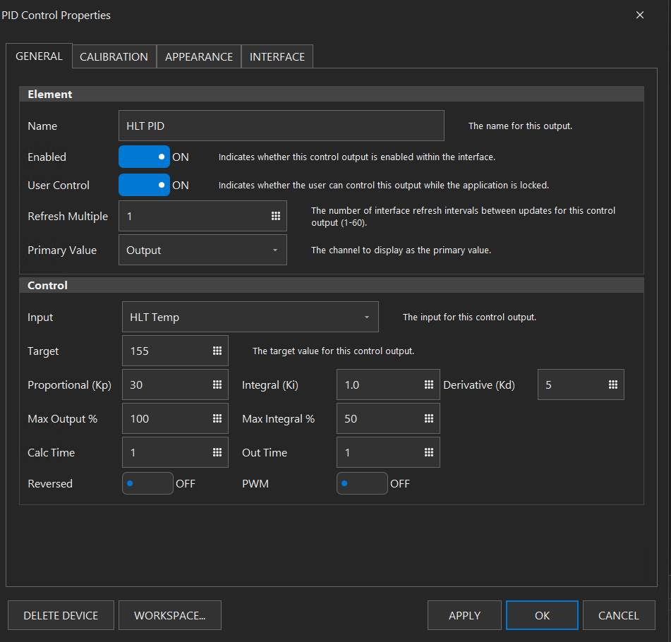
I am trying to get my PID working correctly for PWM cooling with water flow via a valve, both PID's shown here are default other than Kp being set to 10, and PID 2 being 'reversed'.

Why is there no action on PID2 when the input crosses the target?

Why is it -255, that seems very unorthodox.

How do I get a properly working PID that will have the out put go *on* when the input goes above the target?

https://www.bitchute.com/video/IS9GHXg8onDw/

OK, I am not sure what FW my Mega was on, as I could not get it to respond to termite, so I upgraded it to 45K, and it now works... this is the first time the PID for cooling has acted like the Sestos it is replacing...

I ended up using Kp of 0.8 and left Ki and Kd at zero, I tried to use Ki, but even with a calc time of 10 and Ki of 0.01, it would wind up too much, part of my problem is the sensor location is not ideal and introduces significant delay, I will try Ki again after I tig a fitting to move the probe from near the outlet to more towards the middle of the condenser... once it is doing it's thing, it is pretty uneventful.
1608484687245.png
1608485547498.png
 
Hi everyone. I'm new to the forum and nearly done with the build of my controller.

I have a problem I haven't seen asked in the first 65 pages or so of this thread. When I create any number of PID elements and assign a working PT100 as the input, the PIDs never display anything other than 4 dashes. I can enable and disable them and they never change on their own.

1608512130182.png


If I look at the communications with the MEGA controller on the UniShield, I see ?38?47 being transmitted and ?38=825?# being received. The HLT PID is on port 47 and linked to HLT Temp RTD on port 38 reading 70.2 F after calibration. In the picture above, the PID Target is 163.

Interestingly enough, if I create a Duty Cycle element on the same port, enable the DC, then enable the PID, the PID will start displaying Value, Input and Target correctly, however it acts like a DC even though the DC is disabled. I can see this on the SSR as the LED there cycles on and off every second.

I'm running 1.1.9 on Windows Server 2016. I have gone back to my original 1.1.4 and see the same behavior.

Any ideas what I'm doing wrong?
 
Since you are getting ?# it means that port 47 isn't registering correctly.

Also, when you enable a DC on port 47, the PID on that port should be disabled.

What firmware version do you have? IIRC this is on a UniShield? Please email us the controller log (in the Documents\Brucontrol folder. Please continue to use 1.1 Build 9, and do not revert back to 1.1.4.
 
Since you are getting ?# it means that port 47 isn't registering correctly.

I figured that was the case.

What firmware version do you have? IIRC this is on a UniShield? Please email us the controller log (in the Documents\Brucontrol folder.

Yes the UniShield I picked up from you in FL back on 11/14. Haven't changed the firmware (BruControl v45O.E).

Please email us the controller log (in the Documents\Brucontrol folder.

This is all that is in my controller log with today's date...

14:22:52.891: File created 12/20/2020
14:22:52.907: Device 'Garage BCU' @ 192.168.100.25 = Connected
14:38:19.489: Device 'Garage BCU' @ 192.168.100.25 = Disconnected
14:39:43.786: Device 'Garage BCU' @ 192.168.100.25 = Connected
14:53:11.010: Device 'Garage BCU' @ 192.168.100.25 = Disconnected
15:02:57.278: Device 'Garage BCU' @ 192.168.100.25 = Connected
15:34:21.611: Device 'Garage BCU' @ 192.168.100.25 = Disconnected
15:34:30.673: Device 'Garage BCU' @ 192.168.100.25 = Connected
15:39:28.898: Added workspace 'Workspace 1'.
16:02:54.674: Device 'Garage BCU' @ 192.168.100.25 = Disconnected
16:02:54.720: Device 'Garage BCU' @ 192.168.100.25 = Connected
16:20:37.127: Controller locked.
16:20:43.533: Controller unlocked.

Do you want the interface log?
 
Last edited:
Update:

1608525583393.png


After Peter worked on my issue for a bit, we determined that the Pt100 MAX31865 board, one of a set of 4 I purchased from Amazon but were delivered over a couple of weeks, was a Pt1000 board with a Ref Resistor of 4300 (4301 on the resistor). The initial value in calibration for the Ref Resistor calculation returned by the board was 800+, not the expected 8000+. This mix of components and values allowed the correct temperature to show in BC after calibration, but prevented the PID from showing anything other than all dashes.

Peter had me measure the resistance of probe and it was 108.4 at 21 Celsius. So that was a Pt100 probe (also bought from Adafruit in the order below).

About a month after I bought those boards I read an old post here that talked about inconsistent results between batches of these boards so I bought 8 Pt100 MAX31865’s from Adafruit to have just in case. One of the newer boards was in my RTD amp so I switched to it and everything is working now with a Ref Resistor value of 430 and the PID displaying correctly.

Thanks, Peter! You rock and I really like BruControl!
 
I would agree that adding an element location/size lock that is separate from the lock on the functional aspects of the element would be very helpful. I find that I need functionally unlocked elements on my workspace for various reasons at times but once the workspace is set up, I would guess few need element relocation on the workspace to be so easy to achieve. It ends up that some elements can get moved around by an errant touch on the display or stray mouse click & drag. Given how alignment and sizing of elements can be tedious, an unplanned element move/resize can be frustrating. Touch screens and wet fingers can lead to all sorts of funky inputs.
 
I have found it quite frustrating to have elements move/resize on accident. This would be really helpful.

Another idea that just came to me. I don't explicitly stack elements like @oakbarn, but with my background layout I end up with elements close to each other such that one element will block me from getting to another elements property settings. I have to move the overlapping element to get to the other element with a higher Z order.

It would be nice to have an "element browser" from the main settings menu that would allow you to scroll through a table that shows some basic info for each element like name/alias, interface/pin, element type, workspace, location/size, etc. From here you could also get to the elements property settings.
An example where an Element seems to relocate on its own when I was editing a Script
element moved on on.png
 
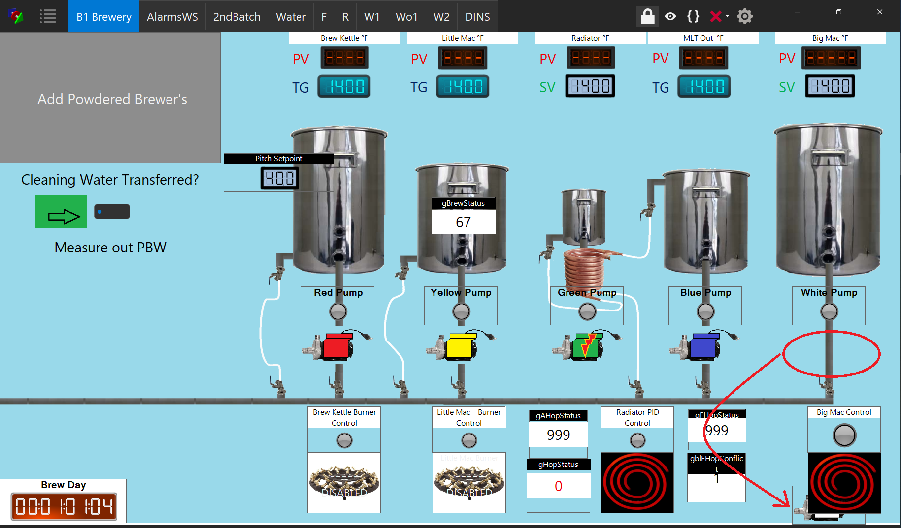
Can someone point me to a way how to generate the great graphics on some these builds? Looks way cooler than flat icons!
 
Since you have it working in hardware, you just select the “Use PWM” switch on your PID element. The output will be a PWM % rather than a duty cycle %.


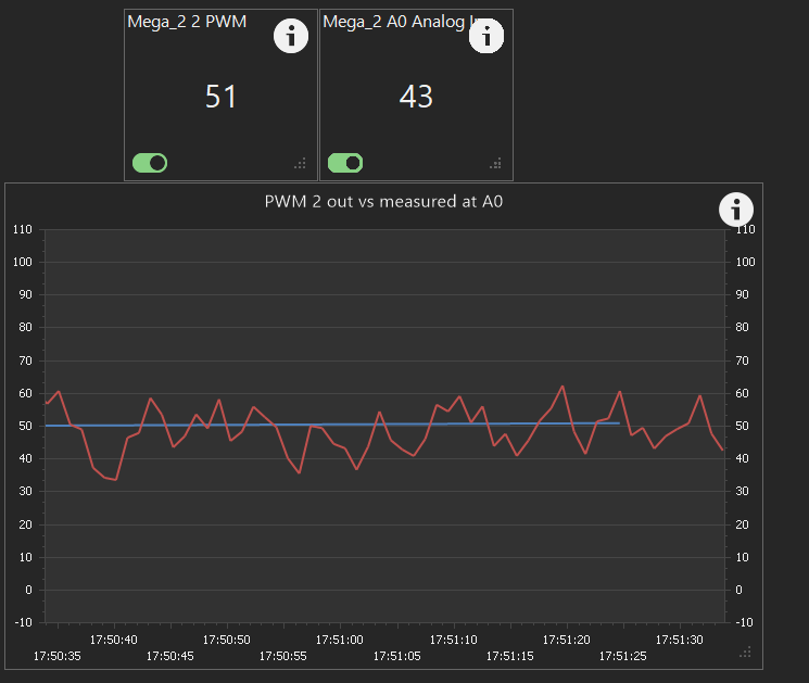
@BrunDog - I am debugging a weird issue, my 45K Mega seems to be outputting a pulsed voltage as seen on a multimeter whether or not I have the PWM switch enabled or not. (it seems to be doing 'duty cycle' all the time). The PID device is on output 2... the blue wavy line is supposed to be straight, the PID output never changes from 53, but the output signal from the mega is giving pulses, and the valve feedback signal is showing the valve constantly cycling. as you can see the PWM is on.

1608656444131.png


Update: I removed and re-added the PID, and now I get the '----' in the display if I set the PWM to on right away... It seems that if you create a *new* PID Control device and set the PWM to 'ON' right away, you get the '----' in the display.

You can make the display appear by switching PWM to 'off', saving, and setting it back to 'on', but you can see that PWM is not actually working, it is still duty-cycle pulsing.

I repeated this several times, it happens on both Mega and ESP32 in 45K(mega)/45N(esp32) in 1.1.9
 
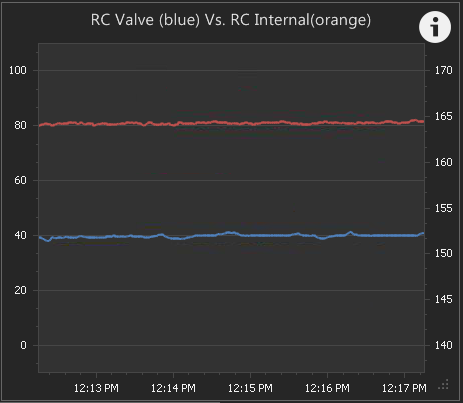
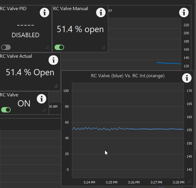
Here is the graph of the valve position feedback. The PID output is maxed at 51.4 with a combination of the 3.9F * Kp providing the 1.4%, and the Ki with Max integral set to 50% providing the 50%.. The calculated and displayed PID output is steady at it's maximum, however the *actual* output at the pin 2 of the Mega is being pulsed as duty-cycle.. Then I enabled the 'RC Valve Manual', which is PWM, which automatically disables the PID... on manual PWM I had the output pre-set to 51.4% open, and you can see real PWM output being steady enough to not modulate the valve.

yes, I could lower the 'Out Time' to 1, but that does NOT stop it, it just makes it harder to see on the graph. (if you hook up a multimeter, you see the pulsing of the duty-cycle). Additionally, that value is not supposed to be active if the PWM switch is 'ON'.
1608668901433.png
 
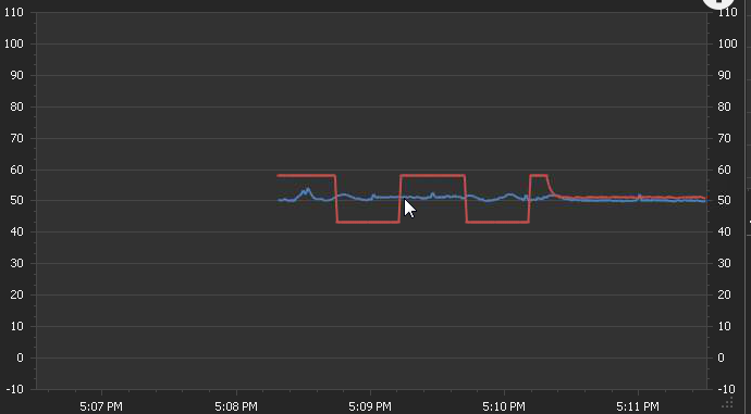
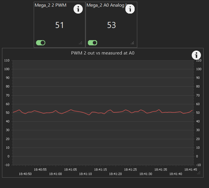
I hooked up another analog input (with voltage divider ) direct to the output of the analog amplifier output driving the valve signal (I tried direct pwm to analog input, but it jumped all over the place due to sampling, so I used the filter built into the AA-1), here is valve position(blue) vs the 0-10v output signal from the AA-1 you see the square wave end and go straight to 50% when I enable the manual PWN and it disables the PID PWM (not sure why the blue line on the left is not as wavy as before, need to research that)
1608675280421.png
 
Hmmm... it's *possible* that 45K does not adequately follow the 'Use PWM' switch. We made some edits along the way and I'm not sure exactly when it was added.

I just posted 45O... give that a rip and see if it works correctly!
 
Hmmm... it's *possible* that 45K does not adequately follow the 'Use PWM' switch. We made some edits along the way and I'm not sure exactly when it was added.

I just posted 45O... give that a rip and see if it works correctly!
May I ask if version "O" prerequisite for next release?
 
Hmmm... it's *possible* that 45K does not adequately follow the 'Use PWM' switch. We made some edits along the way and I'm not sure exactly when it was added.

I just posted 45O... give that a rip and see if it works correctly!

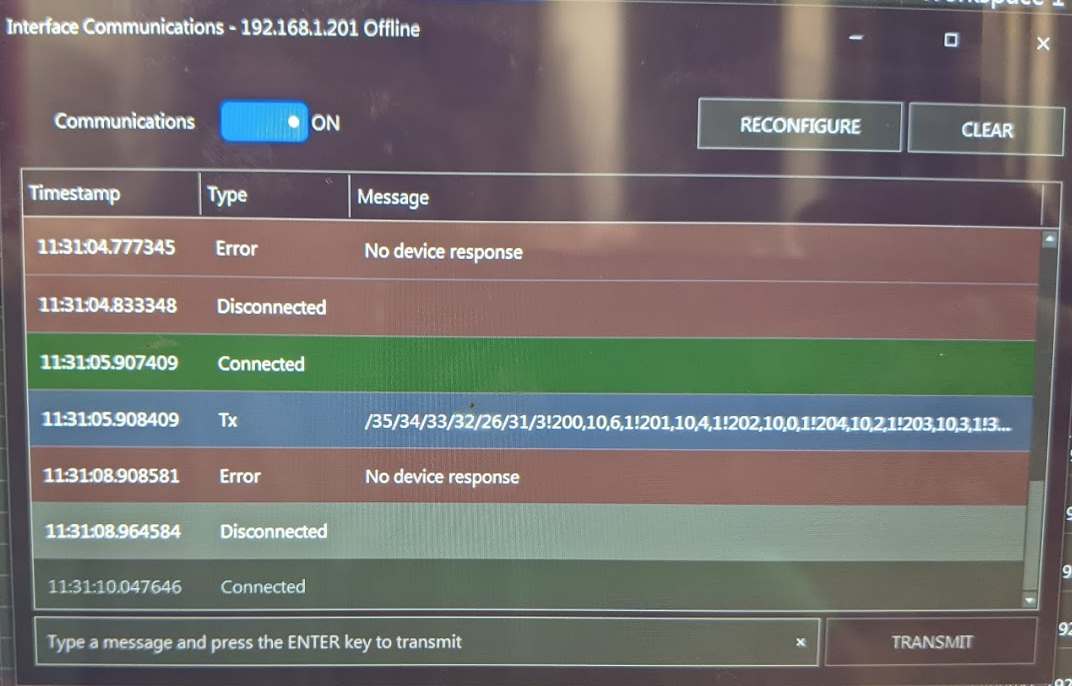
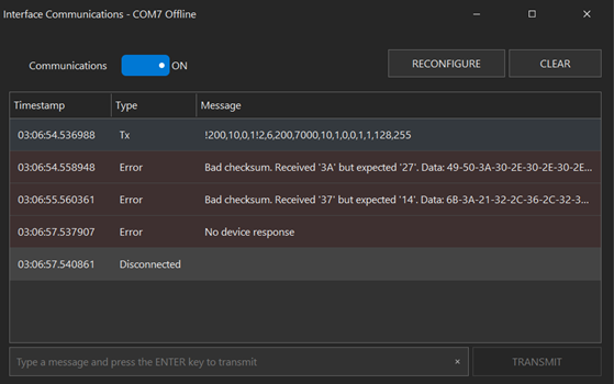
ummm.. I removed my sunfounder Mega2650R3 w piggyback 5500 from the screwshield in my production panel, took to my office, loaded 45O, put it back in the production panel and no communication... took it back off and programmed to 45K, returned it to the panel, and it worked. I repeated this process a total of three times. I have it back on 45K now... also, I have Mega digital output 36 connected to a contactor that energized my chiller, and I noticed that it goes on and then off when normally powered up and communications, but during this communication error, it never shut back off... are certain GPIO's susceptible to this like they are with the Raspberry Pi?

1608745578720.png
 
My problem is that production setup is not capable of debugging during use, as it uses ethernet for communications, and usb port is too far from the brucontrol server (intentionally, as to not get water spray, or overheat in a splash-proof cabinet). I will set up a lab where I can test the features I use...
 
Let me get my lab set up so I can get repeatable results in a green-field environment.. I tested at home with a similar Sunfounder mega (but USB connected) and had issues with communication errors on 45O, but they disappeared after going back to 45K and then forward to 44O... makes no sense... I got a new mega and ethernet shield from keyestudio coming from Amazon tomorrow and will hook up some I/O to mimic what I have in production.
1608757191711.png
 
1.1 build 9

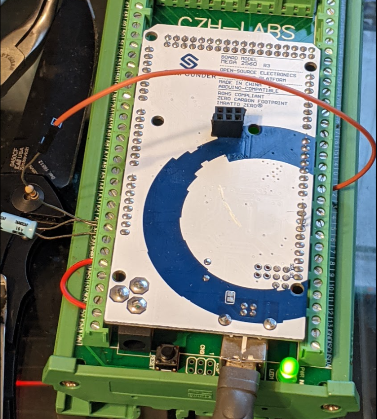
Do you have recommended specs for a low-pass filter to connect a PWM output back to an input on a mega? I used a 100ohm between output 2 and input A0, and 10uF from A0 to Gnd, and still get a lot of noise. and weirdly, the blue line is the PWM, it rolls off the graph until I change it..
1608763905124.png
 
Alright, facing opportunity #2. I am trying to get my CZH-LABS DIN Rail Mount 4 Channel 12 Amp Solid State Relay SSR Module running. I have each of the IN+ connected to UniShield ports 6-1D thru 6-4D. The IN- are connected to ground (AC & DC tied together). I don't get any Digital Output voltage on any of those ports. I originally had 5V hooked up to VB and then tried 24V this afternoon, same zero output. I had a voltmeter on it and there isn't a flicker of voltage change. Any ideas?
 
Alright, facing opportunity #2. I am trying to get my CZH-LABS DIN Rail Mount 4 Channel 12 Amp Solid State Relay SSR Module running. I have each of the IN+ connected to UniShield ports 6-1D thru 6-4D. The IN- are connected to ground (AC & DC tied together). I don't get any Digital Output voltage on any of those ports. I originally had 5V hooked up to VB and then tried 24V this afternoon, same zero output. I had a voltmeter on it and there isn't a flicker of voltage change. Any ideas?

Might be a silly question, but do you have power to the bank those outputs are driving from? Before connecting anything, for a port/pin that is ON as a digital output, you should see 5V (MEGA) or 3.3V (Grand Central) on the P pin, and the same voltage as the bank (VA, VB, etc.) on the D pin.

Note: Make sure you NEVER put positive voltage above Vcc on the P pin. The density of the P and D pins so close together can make this difficult to ensure, admittedly.
 
My problem is that production setup is not capable of debugging during use, as it uses ethernet for communications, and usb port is too far from the brucontrol server (intentionally, as to not get water spray, or overheat in a splash-proof cabinet). I will set up a lab where I can test the features I use...
Since I am rebuilding, one consideration I am making in my Build is that the USB port of any interface is accessible. Is there any reason not to leave a USB cable attached to the interface while the upstream USB A Connector(the end attached to a computer) is left unconnected? I plan to add these to the exterior side of my Interface enclosure: https://www.l-com.com/usb-waterproof-usb-a-panel-mount-jack-female-to-female. I found those small Micro USB connectors on Mega Interfaces very fragile. All of my interface devices will be powered via a separate Power Supply rather than USB.
 
I am getting ready to rebuild my control panel. I plan to do the same and have one usb port for each mega. I bought similar usb panel mount cconnectors as well.
 
Yes, VB is the bank and it had the 5 VDC and now 24 VDC applied to it.

EDIT: I checked 6-1P through 6-4P and none of them is putting out any voltage.
That's odd, since the P type pins are directly tied to the microcontroller pins. Did you cross-checked the port# to the UniShield pin number per the Interface Wiring Map?
 
Hi all. I wish everyone a Merry Christmas, Happy Holidays, and hope everyone sees our lives get back to normal in 2021! I really appreciate this community and I'm thankful to work with you on your brewing projects in any way I can.

FYI just posted 1.2 Beta v1.1.0.15. Please note this uses a new license server, so let us know if you have any issues activating. It includes some fixes and the start of the Profile Element (not complete yet).
 

Latest posts

Back
Top