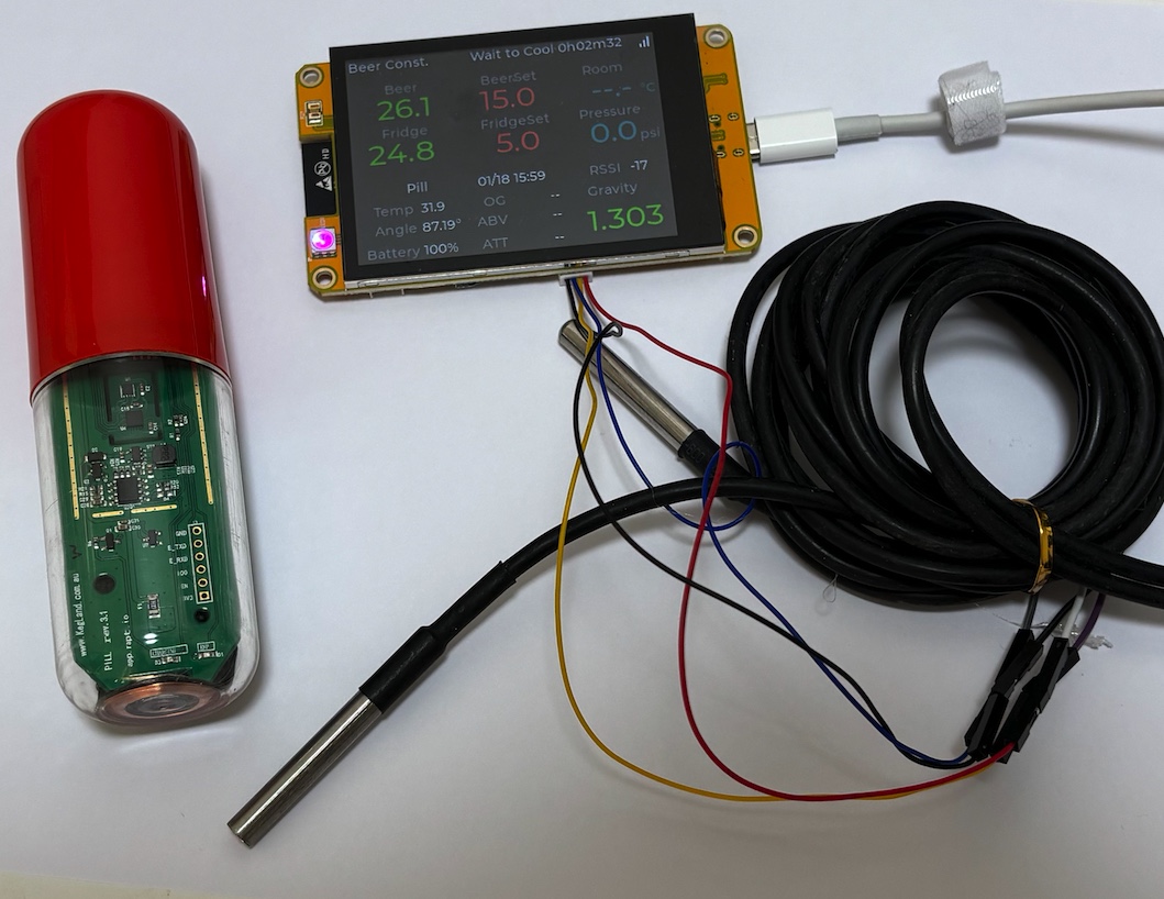
BrewPiLessGx: BrewPiLess with Touched TFT display

Homebrew Talk - Beer, Wine, Mead, & Cider Brewing Discussion Forum

Help Support Homebrew Talk - Beer, Wine, Mead, & Cider Brewing Discussion Forum:

This site may earn a commission from merchant affiliate links, including eBay, Amazon, and others.

pocketmon

Well-Known Member
Joined
Oct 12, 2015
Messages
794
Reaction score
286
brewpilessgx.teasing.jpg


I know, I know. The old 20x4 LCD looks like coming from last century. We now have cheap TFT display with touch control. So, here it is.
Forgive my bad naming skill/taste. BrewPiLessGx is a BrewPiLess with Graphics interface. So the display enables us to
- Set control mode and temperature with touched screen
- Select network and enter pass phrase
- Display the infomration in the way as desired. I created a JSON format for describing what and how the information is shown. It is so flexible that I am thinking about creating an editor for it.

(I am bad at hard ware building. It would take too long to verify. Therefore, I will make a beta release soon, so that people interested can try it.)

To Be continue...
 
Brilliant, will this still be programmable, monitored from web display as well?
I have one of these on the shelf without touch screen hence I'd need to control the old way.
://www.aliexpress.com/item/1005003936535877.html?spm=a2g0n.order_detail.order_detail_item

Would it work on your update or on the old system?
I don't know. It uses the same display driver with mine. Maybe with the same wiring, it would work. The web interface is almost the same as the old/current BPL.

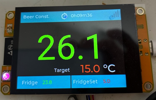
The other built-in skin for those who don't use iSpindle, Tilt, or Pill:
bplgx.brewpi.jpg


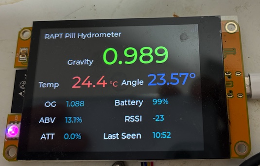
I might use this before I build a new controller:
bplgx.pill.jpg
 
I don't know. It uses the same display driver with mine. Maybe with the same wiring, it would work. The web interface is almost the same as the old/current BPL.

The other built-in skin for those who don't use iSpindle, Tilt, or Pill:
View attachment 839520


I might use this before I build a new controller:
View attachment 839521
Right I'll give it a go and update you and others.
 
I recently got the esp32 3.5" capacitive touchscreen and got the file uploaded on it but it's mirrored and inverted, I'm guessing because code is not written for this size? I don't actually want to use this controller for my BrewPiLess system, I only want to use the touchscreen itself but can't figure out how to wire it. I can get power to it with the 5v and GND connected but nothing comes up on the screen.

I used the PCB boards provided on GitHub (stefschin) , the build instructions from https://angrymrtom.github.io/piless-brewpi/ and built a system with a separate esp32 dev.

Any help would be greatly appreciated.

I know having two esp32 controllers and only using one is a bit stupid, but I didn't like any of other options I found.

Also having issues with BrewPiLess connecting to my iSpindel... This whole project has been a mess since I am a complete noob when it comes to PCB boards and code.
 
There's a flag -D TFT_FLIPPEDMIRRORED commented out in the platformio.ini file, maybe try again with that enabled?
 
There's a flag -D TFT_FLIPPEDMIRRORED commented out in the platformio.ini file, maybe try again with that enabled?
I tried that and it didn't change anything. I have to admit, I'm in way over my head and have been messing around with this thing all day with no luck.
 
To get another IO, could you remove R4 and reroute IO26 to one of the speaker connections (after cutting that speaker connection track to U5)? Then tell BrewPiLess that IO26 is going to heater relay for example?

1709603213268.png
 
I tried that and it didn't change anything. I have to admit, I'm in way over my head and have been messing around with this thing all day with no luck.
Check the build_flags section for the env: you have set as default at the top of the platformio.ini file. For mine [env:ESP32_2432S032C], The line:
-DTFT_FLIPPEDMIRRORED
appears uncommented near the end like below. Maybe try removing that line if your "env" section uses it? (Sorry, I'm also new to this!)

[env:ESP32_2432S032C]
platform = ${common_env_data.esp32_framework}
board = esp32dev
framework = arduino
board_build.mcu = esp32
lib_extra_dirs = ${common_env_data.esp32_lib}

board_build.partitions = ./partition.csv

board_build.embed_txtfiles =
src/skins/skin_brewpi.json
src/skins/skin_info.json

build_flags = -Wl,-Map,output.map
-DESP32_2432S032C
-DTFT_FLIPPEDMIRRORED
In vscode/platformio, to uncomment means to remove the # correct?
To get another IO, could you remove R4 and reroute IO26 to one of the speaker connections (after cutting that speaker connection track to U5)? Then tell BrewPiLess that IO26 is going to heater relay for example?

View attachment 843299
I've always had trouble reading these types of schematics and avoid at all cost haha. I've scrapped the GX display idea and am going to try a basic tft 3.5" lcd (not even sure I said that right). My issue is figuring out where to connect it to which headers on the PCB board. It took an embarrassing amount of time trying to figure out how to get the relays to switch the heater/fridge on, but eventually figured that part out.
 

Attachments

  • esp32 BrewPiLess.jpg
    esp32 BrewPiLess.jpg
    1.3 MB · Views: 0
I hate wiring, and that's the reason I bought a "module".
I tried a few LCD driver and finally SmartDisplay library works after some fiddling, and I am reluctant to change to more generic driver library.
Reversed color, flipped display, and etc. are common issues in LVGL porting. I learned that even with the same product ID, different batches might have different settings. Good luck.
I downloaded a couple libraries in Arduino IDE but I don't know enough (i.e. none) coding to be able to fiddle much. Whenever I did change anything, it just threw errors and wouldn't flash at all. The only thing I was able to do was get a 0.96 lcd to finally load by changing the height to the one I had. I'm on the verge of bifocals so that isn't going to work for me haha. Worst case scenario is no screen at all and just live with viewing the data from my laptop/phone.
 
I hate wiring, and that's the reason I bought a "module".
I tried a few LCD driver and finally SmartDisplay library works after some fiddling, and I am reluctant to change to more generic driver library.
Reversed color, flipped display, and etc. are common issues in LVGL porting. I learned that even with the same product ID, different batches might have different settings. Good luck.
I totally agree, I think I'll try with two DS2413 on a breadboard with a 4 channel relay board. I thought I only needed one extra IO but I need two extra (heat and solenoid for pressure release). I'll probably put all the IO on one-wire (apart from the pressure gauge) so I can have all the wires come from one area on the breadboard.

(2nd edit: just realized i2c needs both pins 21 and 22 so this edit below won't work).

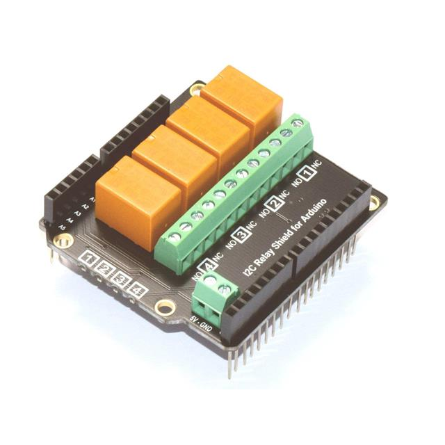
(edit) in case I2C is an option, pins 21 and 22 are also I2C, and there's a 4 channel I2C relay board. I'll still probably go the DS2413 route though as I already have a regular 4 channel relay board.

"Cascadable 4-Channel I2C Relay"
1709696942652.png

Can control relays with I2C on pin 21, read temperature monitors on 22 and pressure on 35. Or just use two DS2413 and a regular 4 channel relay board (each DS2413 can control 2relays).
 
Last edited:
I downloaded a couple libraries in Arduino IDE but I don't know enough (i.e. none) coding to be able to fiddle much. Whenever I did change anything, it just threw errors and wouldn't flash at all. The only thing I was able to do was get a 0.96 lcd to finally load by changing the height to the one I had. I'm on the verge of bifocals so that isn't going to work for me haha. Worst case scenario is no screen at all and just live with viewing the data from my laptop/phone.
I was lucky, with my setup it worked more or less from the beginning. I'm sure it will be worth revisiting the project again once it has had a little time for the parts you need to slot into place. Good luck!
 
I'm a glutton for punishment and am going to try this project again, I'm confused about the four-pin temp sensor tho. Do I need to get a four-wire probe? Please forgive my ignorance, I tried to find some documentation on how to wire this thing but came up with nothing. @pocketmon, are you able to share photos of your set-up besides the ones posted above?
 
I'm a glutton for punishment and am going to try this project again, I'm confused about the four-pin temp sensor tho. Do I need to get a four-wire probe? Please forgive my ignorance, I tried to find some documentation on how to wire this thing but came up with nothing. @pocketmon, are you able to share photos of your set-up besides the ones posted above?

I haven't built a working setup. The four-wire connector came with the display module and is the only connector I have. The temperature probes are DS18B20, which uses OneWire bus. The four-wire socket has 3V3, GND, and two IO Pins. One one the IO pin can be used to control relay(heating or cooling).

BTW, I am thinking about getting a WT-32 SC01 Plus, which has more IO pins available.
Ahh that all makes sense. I ordered the same display (hopefully) is listed on GitHub and will play around with it. I finally finished my BrewPiLess set-up, but like you mention the 20x4 display is from the last century and would like to have something fun to look at.
 
WT-32 SC01 is a nice little development board. I'm curious to see how it turns out! If I could write code, I'd for sure be putting my hands on a bunch of different screens to play with.
 
@pocketmon: have you looked into the Waveshare 4.3in esp32-s3 display? I went ahead and got one to play with and it seems to have the connections needed for a full set-up if you get an RS-485 module to connect into for the heating and cooling switches. Its pricier than most but at 4.3in and its hopeful usage would make it worth it.
 
@pocketmon: have you looked into the Waveshare 4.3in esp32-s3 display? I went ahead and got one to play with and it seems to have the connections needed for a full set-up if you get an RS-485 module to connect into for the heating and cooling switches. Its pricier than most but at 4.3in and its hopeful usage would make it worth it.
I might have come across it, but I didn't think it's a good candidate. I don't have any experience with RS485 and CAN bus.

Having I2C bus is plus, but the PINs are dedicated for I2C bus. I've played with I2C IO expanders, so that expands more than enough IO pins. However, it is difficult to run OneWire protocol over I2C IO expanders. Luckily, the Sensor Port might be able to be used for DS18B20. Adding extra components is something I tried my best to avoid.

The big screen is good, but the high resolution is not. We are running temperature control, web service, BLE scanner, and etc. on the tiny processor with 300~500K SRAM. The higher the resolution, the more RAM it requires. LVGL suggests the size of draw buffer should be 1/10 for better performance, but I've found that I couldn't assign that much draw buffer for 320x240 resolution LCD.

There are too many devices that I can't and won't support all of them. I've integrated LGFX library into the code base, so that it's easier to support new devices that LGFX supports. Try any devices you like. It is encouraged.
 
Apologies if I missed it but has a test binary been released yet ?

I have a CYB here waiting to be put to use.
 
Apologies if I missed it but has a test binary been released yet ?

I have a CYB here waiting to be put to use.
No. Maybe there won't be one. Please take this open source project as your base and build your own.
I've learned there are more number of LCDs people want than the number of people who are interested in this project, I won't build any binary for devices that I don't have for this project, which would only result in more debugging jobs and complaints.
 
I've got an "ESP32 2 Channel 5V Relay Module" with two built in relays to replace the STC-1000 in my IceMaster Max2 glycol chiller so I can control it remotely. (I can switch it on and off now using a switch on a web page).

I am a novice at cpp and platformio. Is there an easy way to modify the "Parasite (Glycol) Temperature Control" part of BrewPiLessGx which expects a local GPIO pin, to use a GPIO pin on a remote esp32 instead?

(I used the tutorial at the following link to program the esp32 I put in the chiller (my one with integrated relays worked without modification to the code apart from the GPIO pins being 16 and 17 for the two relays): https://randomnerdtutorials.com/esp32-relay-module-ac-web-server/
And the platformio.ini:
[env:esp32dev]
platform = espressif32
board = esp32dev
framework = arduino
lib_deps = https://github.com/me-no-dev/ESPAsyncWebServer

I was going to use one of the relays attached to the BrewPiLessGx screen, but it needs to switch 120V AC for the chiller. I wanted to keep the live wire inside the chiller housing rather than running it out to the BrewPiLessGx.
 
Last edited:
I've got an "ESP32 2 Channel 5V Relay Module" with two built in relays to replace the STC-1000 in my IceMaster Max2 glycol chiller so I can control it remotely. (I can switch it on and off now using a switch on a web page).

I am a novice at cpp and platformio. Is there an easy way to modify the "Parasite (Glycol) Temperature Control" part of BrewPiLessGx which expects a local GPIO pin, to use a GPIO pin on a remote esp32 instead?

(I used the tutorial at the following link to program the esp32 I put in the chiller (my one with integrated relays worked without modification to the code apart from the GPIO pins being 16 and 17 for the two relays): https://randomnerdtutorials.com/esp32-relay-module-ac-web-server/
And the platformio.ini:
[env:esp32dev]
platform = espressif32
board = esp32dev
framework = arduino
lib_deps = https://github.com/me-no-dev/ESPAsyncWebServer

I was going to use one of the relays attached to the BrewPiLessGx screen, but it needs to switch 120V AC for the chiller. I wanted to keep the live wire inside the chiller housing rather than running it out to the BrewPiLessGx.
There is no easy way, although it is not too difficult.
There would be a new class for "remote web actuators" which defines the link and relay control. It would be better to have another separated managing class that has an interface for DeviceManager to "find" new devices available and "assign" function for the devices. Not to alter the original structure of device configuration structure, there is no room to store full urls, so the managing class can behave as a proxy for mapping IDs or numbers to real urls.
The web page for device management should be modified, but it's easy compared to the jobs above.

If everything goes right, it would work perfectly. However, There are issues that are hard to handle. When the controller is powered up, the relays are "reset". However, the controller usually hasn't connected to the network at the 1st second, and it's not possible to "reset" the remote relay. Even worse, what if the network is lost? In my experience, 80%(even more) of the development time was spent for 20%(even less) of the "abnormal" cases. I would avoid a system that is not so robust.
 
Yes losing synch due to network drop etc would be bad. Sounds like I should put a standalone relay board in the glycol chiller and control it from one of the DS2413 1-wire outputs I'm controlling on GPIO22. Thanks for steering me towards a more sensible approach!

A related question: Do you know if you can use a phone-line splitter to connect two DS18B20 temperature probes with RJ11 plugs to one RJ11 wired to the 1-wire GPIO22? Individually both my temp probes work but neither work using a short phone line splitter. Maybe it needs a lower value pull-up resistor, I'm using 3.3V with a 2.2k resistor. (I was trying to make the breadboard a bit more robust by switching from audio connectors to RJ11).
 
How long is the combined length of wires to the two temp sensors? And are they twisted pair or paralleled runs?

2.2K is the recommended pull-up when referenced to 3.3V. You could try 1.8K but I've never had to go below 2.2K and I have One-Wire configurations with 5 sensors each on 3 meter leads starred from a point five feet from an RPi with a 2.2K pull-up to 3.3V and never get even a drop-out.


Cheers!
Thanks @day_trippr there's just two of them on 2m cables coming from the splitter which is three way with a 3" jumper cable to the rj11 socket then another 3" to the esp32. Not twisted pair. Good to know 2.2k works for a more challenging setup. It could be my cables aren't terminated well, it took me a couple of attempts to crimp them so maybe just good enough on their own but not both. I'll check if there's anything wrong with the splitter then maybe get some preterminated rj11 pigtails and solder them to the wires instead.
 
I checked my rj11 splitter and it has a jumper cable that was wired the wrong way around! Fixed that now and the probes all work via the splitter!

For the glycol chiller I've ordered a 12V relay with spade connectors for the 120V side and I'll drive that relay with one of the two spare relays on the 4-relay board, powered by the 12V in the chiller (the remaining one is for spunding). I found I needed to control the glycol temperature to reduce overshoot when cooling. Trying to maintain 20C with 4C glycol would overshoot with only a short pump on time, so I intend to run the glycol at 12C for that stage and ~4C or somewhere in between when colling below 20C).
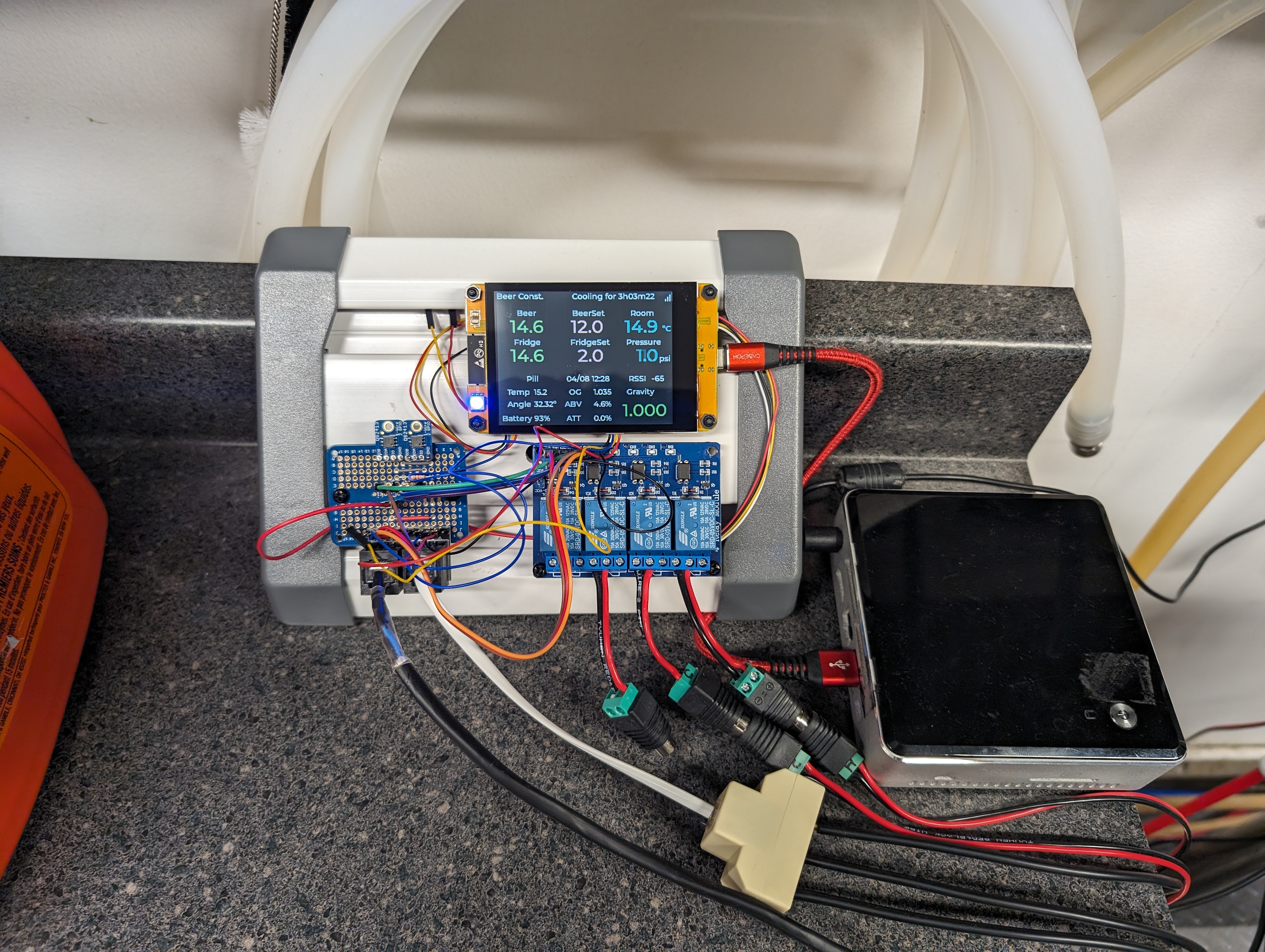
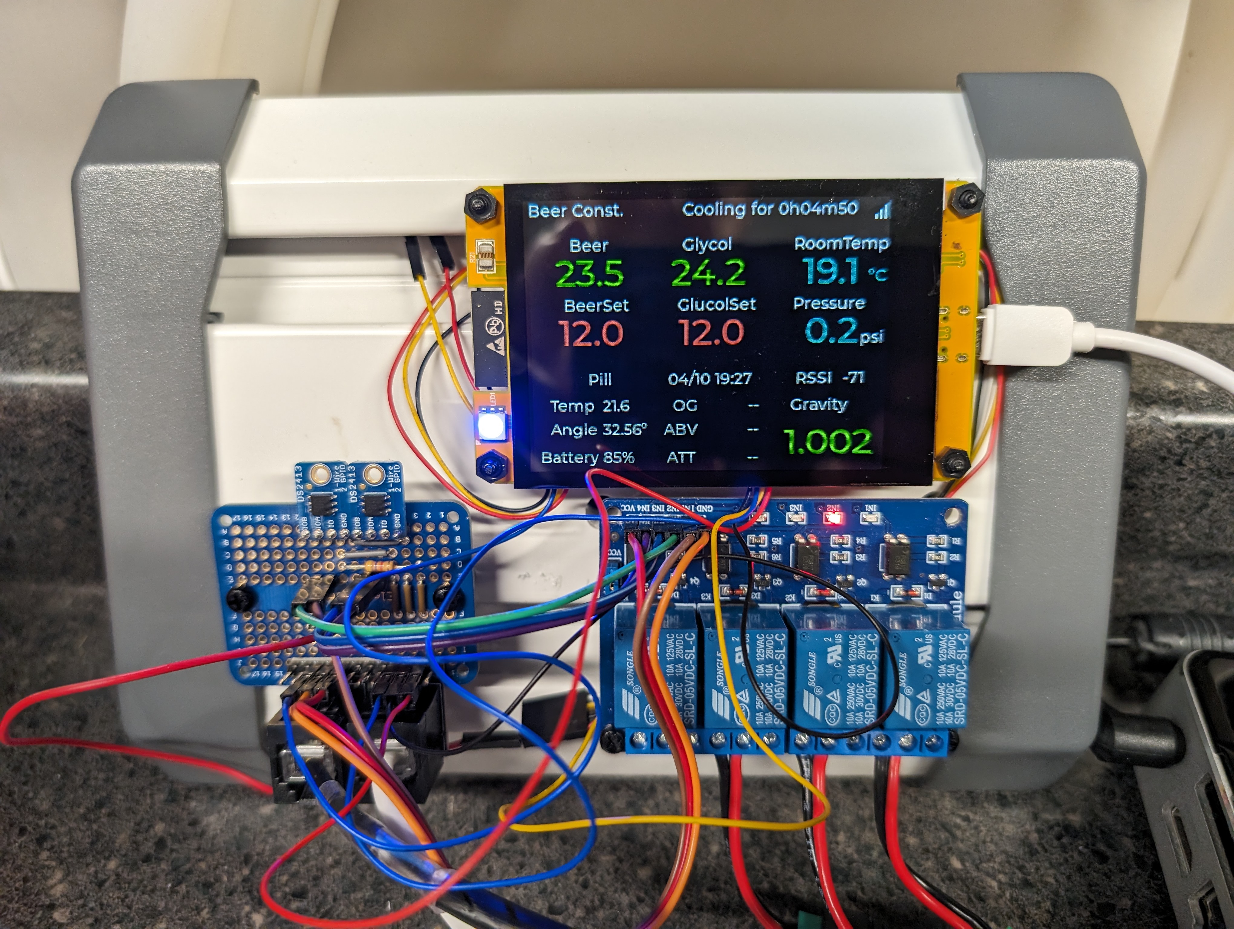
BrewPiLessGX_040824.jpg


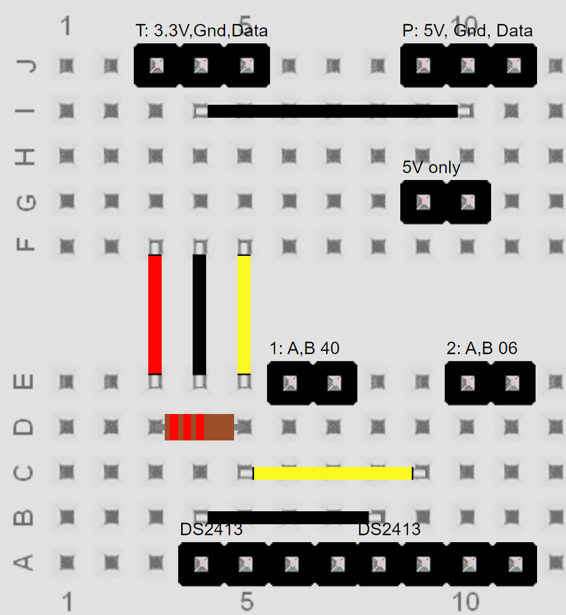
I found a handy tool for laying out the breadboard called Pebble:
1712608864834.png

This is what you paste into PEBBLE to give the above layout. It installs locally but displays in a browser.

Terminal||92|88|1||TS?||3|4|T: 3.3V,Gnd,Data||terminal_431
Terminal||254|88|1||TS?||3|4|P: 5V, Gnd, Data||terminal_431
Terminal||227|391|1||TS?||4|4|DS2413||terminal_441
Terminal||119|391|1||TS?||4|4|DS2413||terminal_441
Wire||155|209|21||11|#FFFF00|3|11||10|
Wire||128|209|21||11|#000000|3|11||10|
Wire||101|209|21||11|#FF0000|3|11||10|
Wire||157|345|11||11|#FFFF00|4|11||10|
Wire||130|372|11||11|#000000|4|11||10|
Resistor|2200|105|313|1|Resistor|R?||1||IC||
Terminal||281|281|1||TS?||2|4|2: A,B 06||terminal_421
Terminal||173|281|1||TS?||2|4|1: A,B 40||terminal_421
Wire||130|125|11||11|#000000|6|11||10|
Terminal||254|171|1||TS?||2|4|5V only||terminal_421
BREADBOARDSTYLE=BB12
SHOWTHETOPAREA=false
 
Last edited:
I am happy to see that it works for you.
You might wanna change the "Room" label to "Glycol" and maybe ditch FridgeTemp and FridgeSet.
You can use the SkinEditor to modify the JSON file.
https://github.com/vitotai/BrewPiLessGx/tree/main/extra/SkinEditor

Copy the contents of /src/skins/skin_info.json, paste the content to the text area, click "input", do some modification, then click "generate". Copy the text and replace /src/skins/skin_info.json with it, or save the text as skin.json.
 
Cool! Once I realized I had to open the file extra/SkinEditor/index.htm in a browser it was easy. I made a table of the existing items and coordinates in a spreadsheet and another with what I wanted, then switched the coordinates and labels.

I did have to re-add the touch screen "click" section from the original to get "touch" working again though.

I looked in the index.htm to see if I could duplicate one of the "set" fields to make a GlycolSet value but not sure what the target would be, maybe gs? (In the photo the "12.0" value is just me faking GlycolSet by using FridgeSet), As I'm already using "Room Temp" to measure the glycol temperature, and I had a spare sensor, I labeled that Room temp in the skin and assigned it to "Chamber temp" in Devices.

Good to see the devices, pressure calibration, and pill calibration settings get saved now (or maybe I wasn't saving / loading them correctly before)

This is great! Looking forward to brewing with it either this weekend or next.

BrewPiLessGX_041024c.jpg
 
Last edited:
GlycolSet is not currently available, It can be added easily as well as the status of glycol cooling. On the other hand, an "extra" temperature reading for real room temperature is more complicated. I implemented this glycol temperature control when I was using glycol to chill my beer in fermentation. I took a short cut and the easiest way to do it. It should've been a dedicated sensor for glycol. I'll see what I can do.
 
@OpenFermenter

The glycol related information is now available. You can use the following tag to display:
- Glycol Temperature: glt
- Glycol Temperature Set: glts
- Glycol status time: gle ( The time since last state changed.)
- Glycol Cooler state: gls ( enumeration(text or icons). 0: Off, 1:Idle, 2: Cooling )
 
Not sure why but I've not been able to get the pin for PTC cooler or capper to change state on one of my DS2413 (2channel 1-wire actuators controlled by PIN 22). The heater and cooler are on one DS2413, the capper and PTC are on the other. All four outputs are detected and configured in "Devices", and both Heat and Cool are working fine. I switched the heater and cooler to using the other DS2413 in "Devices" and they worked fine there too. It is fermenting now and I'm letting an stc-1000 control the glycol and will manually spund. When it is done I'll take off the board to see if I messed anything between the DS2413 and the relay board when I was tidying up the wiring and soldered things in place.

Looks like the capper one is switching on and off correctly. The glycol one doesn't appear to be still but it may be something I've done to the circuit. Will update at the weekend.

Still extremely happy with it though! Having the pill integrated and the temperature control and the customizable display is awesome.
 
Last edited:
I am unable to access the Skin Editor page. I had it open a few days ago, but can't get it now.
 
@akgal12 I cloned the main branch again and can open it (in chrome on ubuntu I'm opening file:///home/<rest of path>/BrewPiLessGx/extra/SkinEditor/index.htm )
 
I've been playing with the WT32-SC01 Plus to get it running on this project but cannot seem to get past a Pressure Monitor error when trying to build. I added the build flag mentioned in the ReadMe file but to no avail.

src/bpl/PressureMonitor.cpp: In member function 'int PressureMonitorClass::_readInternalAdc()':
src/bpl/PressureMonitor.cpp:63:28: error: 'ADC1_GPIOPressureAdcPin_CHANNEL' was not declared in this scope
#define ConcateChanel(pin) ADC1_GPIO ## pin ## _CHANNEL
^~~~~~~~~
src/bpl/PressureMonitor.cpp:64:34: note: in expansion of macro 'ConcateChanel'
#define AdcChannelFromPinNr(pin) ConcateChanel(pin)
^~~~~~~~~~~~~
src/bpl/PressureMonitor.cpp:86:37: note: in expansion of macro 'AdcChannelFromPinNr'
adc_reading += adc1_get_raw(AdcChannelFromPinNr(PressureAdcPin));
^~~~~~~~~~~~~~~~~~~
src/bpl/PressureMonitor.cpp:63:28: note: suggested alternative: 'ADC1_GPIO7_CHANNEL'
#define ConcateChanel(pin) ADC1_GPIO ## pin ## _CHANNEL
^~~~~~~~~
src/bpl/PressureMonitor.cpp:64:34: note: in expansion of macro 'ConcateChanel'
#define AdcChannelFromPinNr(pin) ConcateChanel(pin)
^~~~~~~~~~~~~
src/bpl/PressureMonitor.cpp:86:37: note: in expansion of macro 'AdcChannelFromPinNr'
adc_reading += adc1_get_raw(AdcChannelFromPinNr(PressureAdcPin));
^~~~~~~~~~~~~~~~~~~
src/bpl/PressureMonitor.cpp: In member function 'void PressureMonitorClass::_initInternalAdc()':
src/bpl/PressureMonitor.cpp:154:13: error: 'PressureAdcPin' was not declared in this scope
pinMode(PressureAdcPin, INPUT);
^~~~~~~~~~~~~~
src/bpl/PressureMonitor.cpp:154:13: note: suggested alternative: 'PressureDecode'
pinMode(PressureAdcPin, INPUT);
^~~~~~~~~~~~~~
PressureDecode
src/bpl/PressureMonitor.cpp:63:28: error: 'ADC1_GPIOPressureAdcPin_CHANNEL' was not declared in this scope
#define ConcateChanel(pin) ADC1_GPIO ## pin ## _CHANNEL
^~~~~~~~~
src/bpl/PressureMonitor.cpp:64:34: note: in expansion of macro 'ConcateChanel'
#define AdcChannelFromPinNr(pin) ConcateChanel(pin)
^~~~~~~~~~~~~
src/bpl/PressureMonitor.cpp:157:31: note: in expansion of macro 'AdcChannelFromPinNr'
adc1_config_channel_atten(AdcChannelFromPinNr(PressureAdcPin),ADC_ATTEN_DB_11); // 3.9v scale
^~~~~~~~~~~~~~~~~~~
Compiling .pio/build/WT32_SC01_PLUS/src/bpl/TiltListener.cpp.o
src/bpl/PressureMonitor.cpp:63:28: note: suggested alternative: 'ADC1_GPIO7_CHANNEL'
#define ConcateChanel(pin) ADC1_GPIO ## pin ## _CHANNEL
^~~~~~~~~
src/bpl/PressureMonitor.cpp:64:34: note: in expansion of macro 'ConcateChanel'
#define AdcChannelFromPinNr(pin) ConcateChanel(pin)
^~~~~~~~~~~~~
src/bpl/PressureMonitor.cpp:157:31: note: in expansion of macro 'AdcChannelFromPinNr'
adc1_config_channel_atten(AdcChannelFromPinNr(PressureAdcPin),ADC_ATTEN_DB_11); // 3.9v scale
^~~~~~~~~~~~~~~~~~~
*** [.pio/build/WT32_SC01_PLUS/src/bpl/PressureMonitor.cpp.o] Error 1

This is the text output in VScode. I don't need pressure monitoring... From my research, ADC pins are not available on this display module unless you disable WiFi which I do not want to do.

For reference, this is my addition to the pindef.h file:

#if WT32_SC01_PLUS
#define oneWirePin 21
#define actuatorPin1 10
#define actuatorPin2 11
#define actuatorPin3 12
#define actuatorPin4 13
#define actuatorPin5 14
#endif
 
Last edited:
I've been playing with the WT32-SC01 Plus to get it running on this project but cannot seem to get past a Pressure Monitor error when trying to build. I added the build flag mentioned in the ReadMe file but to no avail.

src/bpl/PressureMonitor.cpp: In member function 'int PressureMonitorClass::_readInternalAdc()':
src/bpl/PressureMonitor.cpp:63:28: error: 'ADC1_GPIOPressureAdcPin_CHANNEL' was not declared in this scope
#define ConcateChanel(pin) ADC1_GPIO ## pin ## _CHANNEL
^~~~~~~~~
src/bpl/PressureMonitor.cpp:64:34: note: in expansion of macro 'ConcateChanel'
#define AdcChannelFromPinNr(pin) ConcateChanel(pin)
^~~~~~~~~~~~~
src/bpl/PressureMonitor.cpp:86:37: note: in expansion of macro 'AdcChannelFromPinNr'
adc_reading += adc1_get_raw(AdcChannelFromPinNr(PressureAdcPin));
^~~~~~~~~~~~~~~~~~~
src/bpl/PressureMonitor.cpp:63:28: note: suggested alternative: 'ADC1_GPIO7_CHANNEL'
#define ConcateChanel(pin) ADC1_GPIO ## pin ## _CHANNEL
^~~~~~~~~
src/bpl/PressureMonitor.cpp:64:34: note: in expansion of macro 'ConcateChanel'
#define AdcChannelFromPinNr(pin) ConcateChanel(pin)
^~~~~~~~~~~~~
src/bpl/PressureMonitor.cpp:86:37: note: in expansion of macro 'AdcChannelFromPinNr'
adc_reading += adc1_get_raw(AdcChannelFromPinNr(PressureAdcPin));
^~~~~~~~~~~~~~~~~~~
src/bpl/PressureMonitor.cpp: In member function 'void PressureMonitorClass::_initInternalAdc()':
src/bpl/PressureMonitor.cpp:154:13: error: 'PressureAdcPin' was not declared in this scope
pinMode(PressureAdcPin, INPUT);
^~~~~~~~~~~~~~
src/bpl/PressureMonitor.cpp:154:13: note: suggested alternative: 'PressureDecode'
pinMode(PressureAdcPin, INPUT);
^~~~~~~~~~~~~~
PressureDecode
src/bpl/PressureMonitor.cpp:63:28: error: 'ADC1_GPIOPressureAdcPin_CHANNEL' was not declared in this scope
#define ConcateChanel(pin) ADC1_GPIO ## pin ## _CHANNEL
^~~~~~~~~
src/bpl/PressureMonitor.cpp:64:34: note: in expansion of macro 'ConcateChanel'
#define AdcChannelFromPinNr(pin) ConcateChanel(pin)
^~~~~~~~~~~~~
src/bpl/PressureMonitor.cpp:157:31: note: in expansion of macro 'AdcChannelFromPinNr'
adc1_config_channel_atten(AdcChannelFromPinNr(PressureAdcPin),ADC_ATTEN_DB_11); // 3.9v scale
^~~~~~~~~~~~~~~~~~~
Compiling .pio/build/WT32_SC01_PLUS/src/bpl/TiltListener.cpp.o
src/bpl/PressureMonitor.cpp:63:28: note: suggested alternative: 'ADC1_GPIO7_CHANNEL'
#define ConcateChanel(pin) ADC1_GPIO ## pin ## _CHANNEL
^~~~~~~~~
src/bpl/PressureMonitor.cpp:64:34: note: in expansion of macro 'ConcateChanel'
#define AdcChannelFromPinNr(pin) ConcateChanel(pin)
^~~~~~~~~~~~~
src/bpl/PressureMonitor.cpp:157:31: note: in expansion of macro 'AdcChannelFromPinNr'
adc1_config_channel_atten(AdcChannelFromPinNr(PressureAdcPin),ADC_ATTEN_DB_11); // 3.9v scale
^~~~~~~~~~~~~~~~~~~
*** [.pio/build/WT32_SC01_PLUS/src/bpl/PressureMonitor.cpp.o] Error 1

This is the text output in VScode. I don't need pressure monitoring... From my research, ADC pins are not available on this display module unless you disable WiFi which I do not want to do.

For reference, this is my addition to the pindef.h file:

#if WT32_SC01_PLUS
#define oneWirePin 21
#define actuatorPin1 10
#define actuatorPin2 11
#define actuatorPin3 12
#define actuatorPin4 13
#define actuatorPin5 14
#endif
I think you'll need to assign a different pin for pressure monitoring (something other than the default GPIO 35) as that pin appears to be used for something else on that device (LRCK, something to do with audio), page 7 on the datasheet:
https://www.antratek.com/media/wysiwyg/pdf/WT32-SC01-Plus-V1.3-EN.pdf

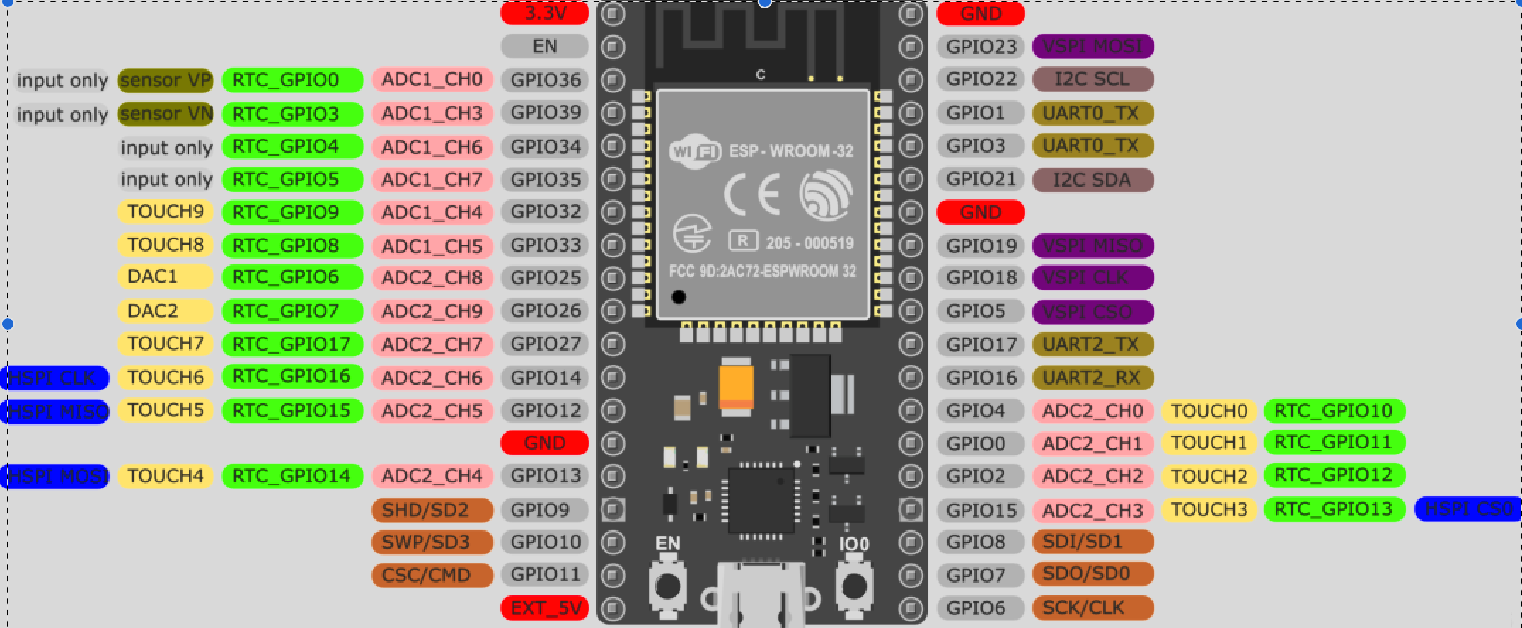
You change the pin assignments in /src/driver/pindef.h Pressure sensor needs to be on a pin that can function as an ADC: pins 10,11,12,13,14,21 are on the I/O connector, 12, 13 and 14 can be ADC. Pin 21 can be assigned to 1-wire. (The diagram below shows the possible pin assignments of an esp32 in general, the pdf link shows which pins are already used by the WT32-SC01 Plus).

I am learning as I'm going along though so this might be wrong and need correcting! @pocketmon is this right?

1713506912251.png
 
Back
Top