Gregredic
Well-Known Member
Pol....I dont see anything in the OP about the price of the control panel. Are you talking about the post that thread that was 240+ posts long?

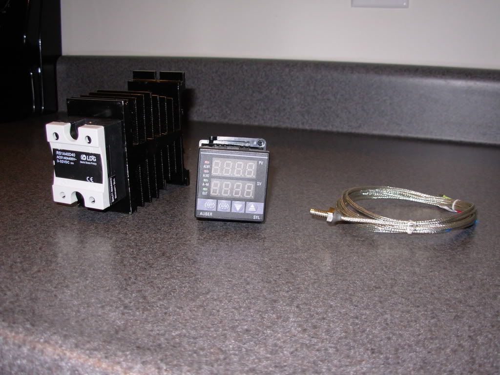
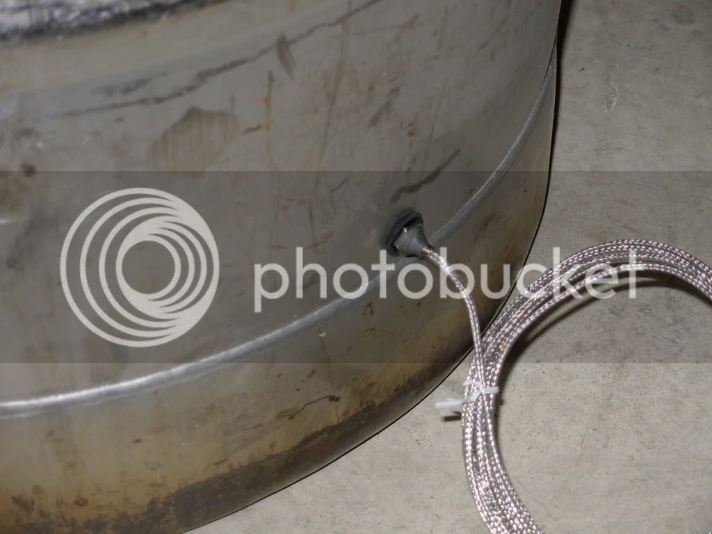
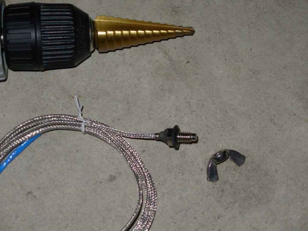
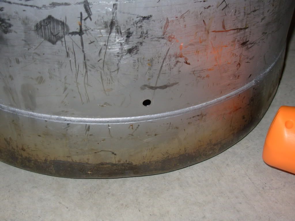
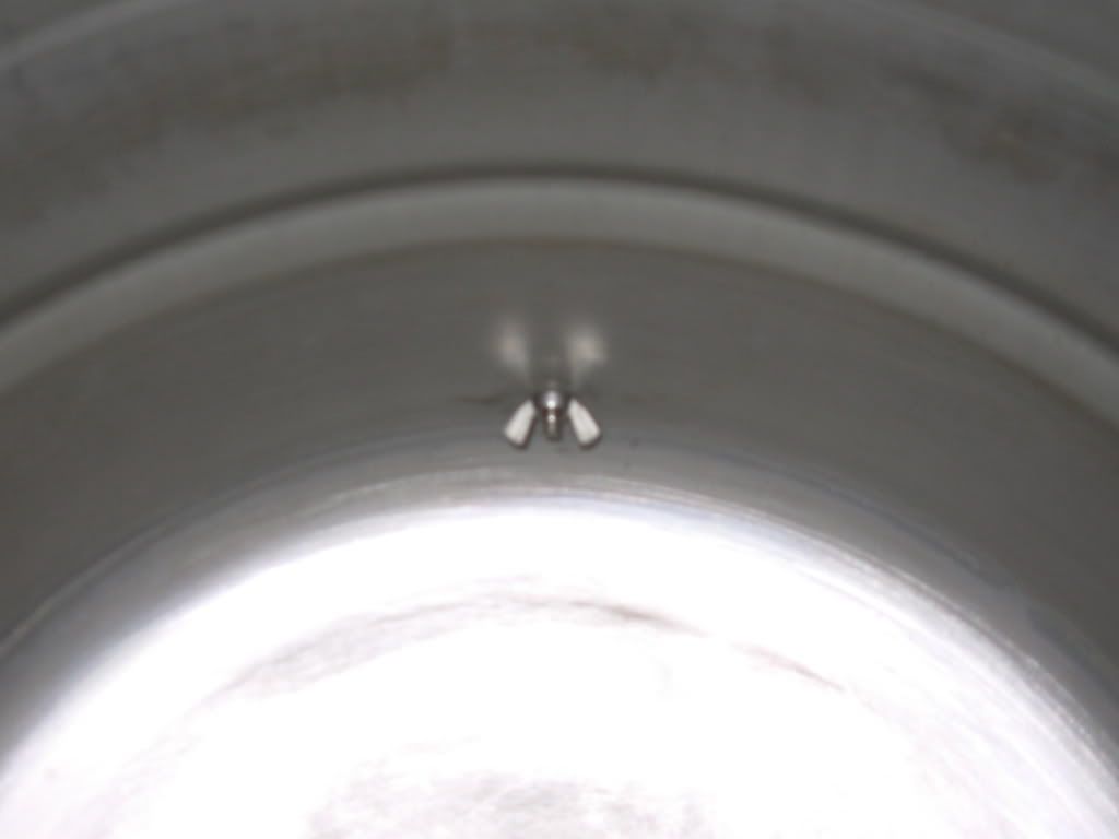
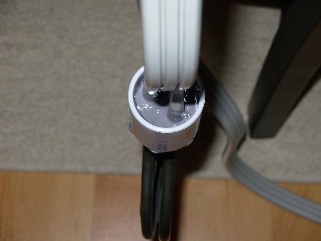
This probe was about $25 less than a probe with a disconnect. I will mount it with a seal and a SS 1/4-20 wing nut inside the keggle so that I can remove it easily to clean the keggle.
Probe length... not really a necessity since it is merely going into the boil kettle. 1/4" long or 3"... it will work the same. Plus it will not get in the way of my chiller coil, heating element, etc. in the keggle already.
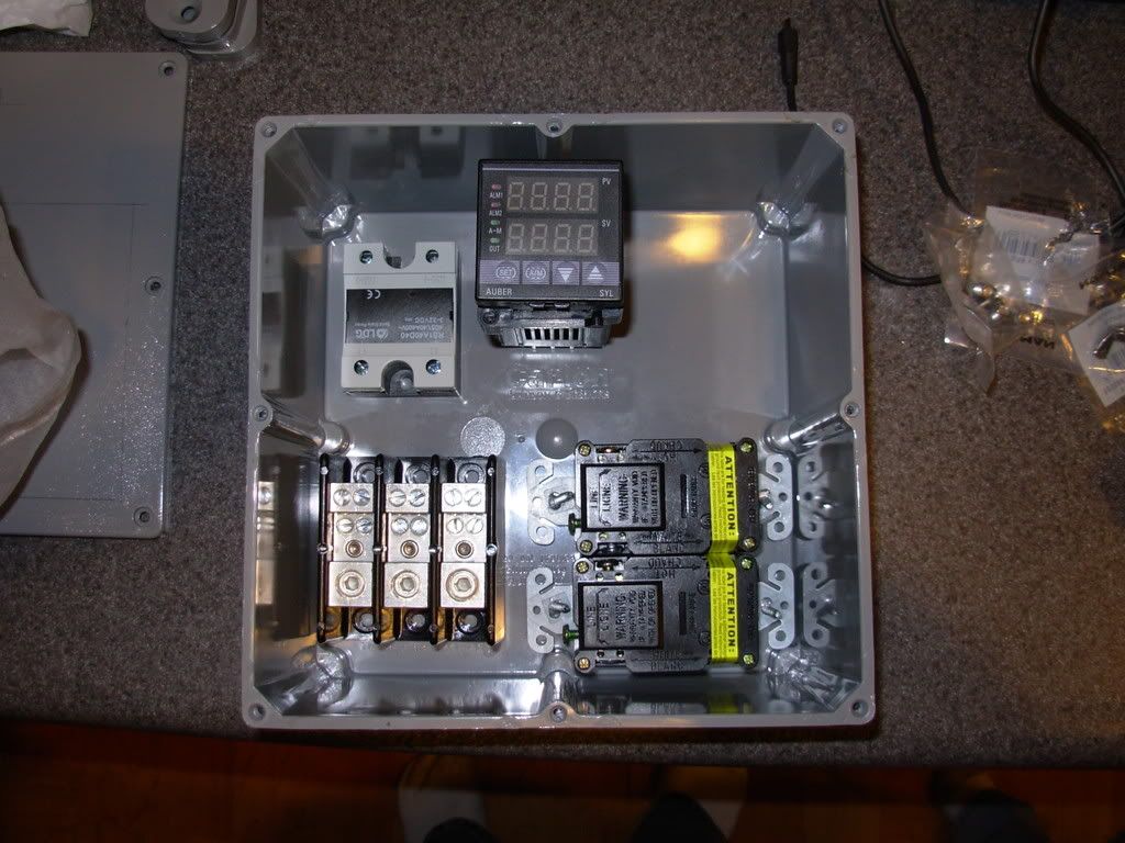
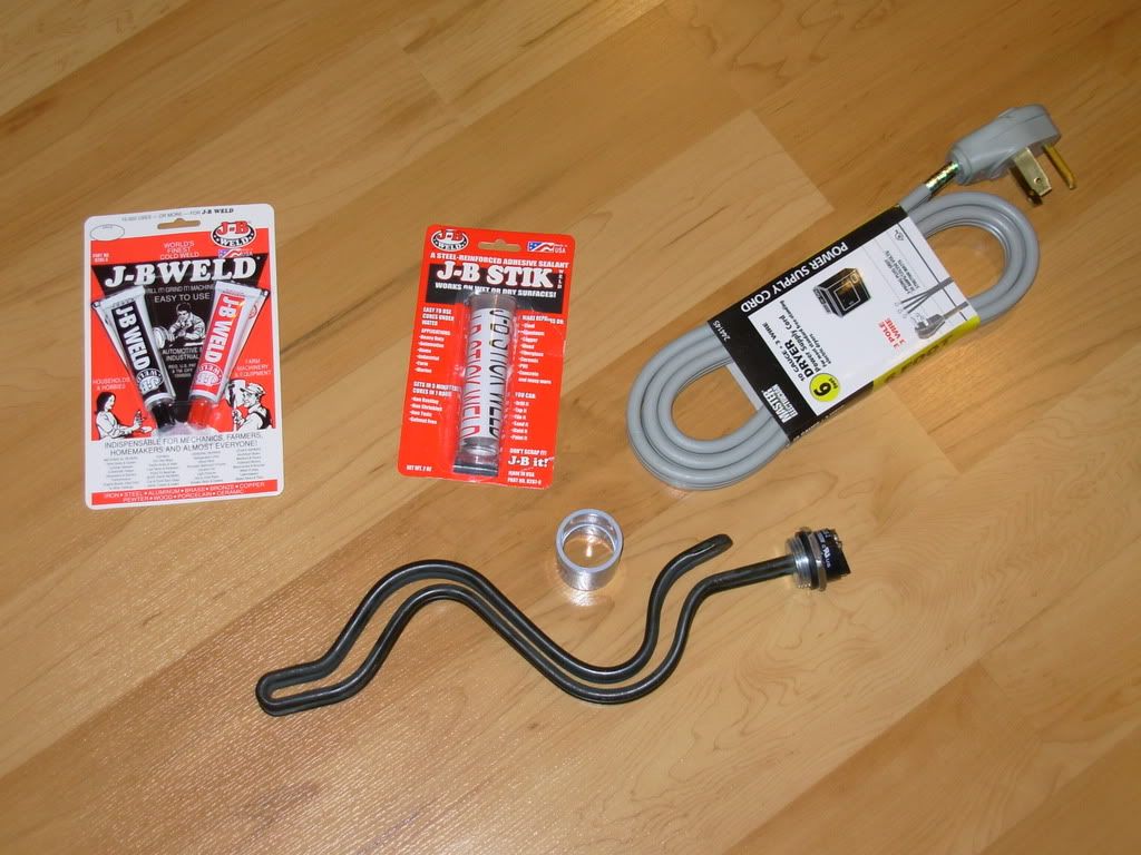
(2) SSRs are not needed, nor is an SSRD. The (2) hot legs to the element will be on a switch... so that regardless of what the PID commands, I can turn off the element completely.
When I power on my panel, the PID will be powered... the BK switch will be OFF, keeping the BK element OFF regardless of the PID command. When I choose to heat the BK I will turn the switch on and the PID will have control of the element in the BK.
When the boil is complete I can turn off the BK element switch, turning off the element, the PID will continue to be powered and will indicate wort temp during the chilling process in the keggle.
Actually today at lunch I spent a little time surfing ebay for SSRs and going to home depot to look at heater element pricing!I think the temp of boiling wort will be pretty homogenous.
I've got a fairly accurate digital with a LONG probe. Moving it around the kettle it's easy to find 10+ degree variances. Sorry if you previously mentioned - whats the need for temperature monitoring in the kettle again?
The purpose of a thermocouple in the kettle? Well, the PID wont operate without a signal from the thermocouple #1. #2 it will be nice to monitor the temp of the COOLING wort as the immersion chiller does its thing.
I dont see why not... assuming of course that I do not kill myself doing this in the coming days!

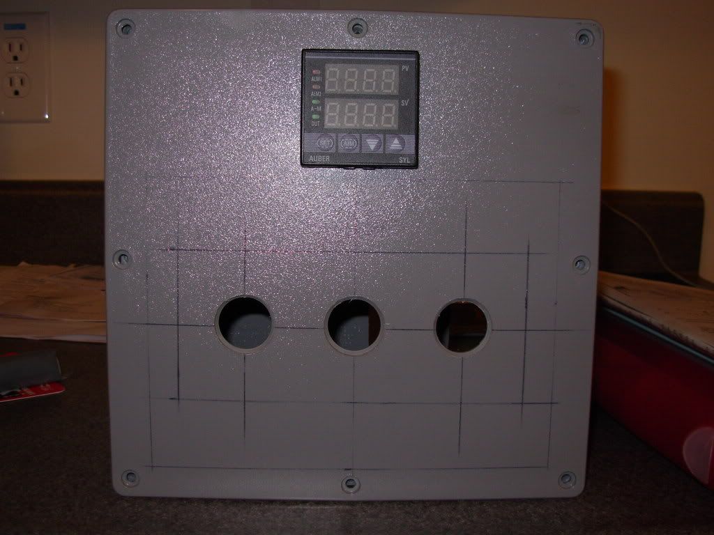
I used a dremmel (sp?) to cut my control box. Worked really well but a hot knife should work too.... I am heading out to buy a hot knife to make the precise cuts in my control box housing for switches and outlets.
HEY, thanks MIKE! I am guessing at the percentages since I have never used a PID for a BK. I generally get about 1.4 gallons of boil off when using a propane burner, thanks for giving me a starting point for the first brew!
Are you using a 5500W element as well for the boil? Are you also brewing 5 gallon batches?
.
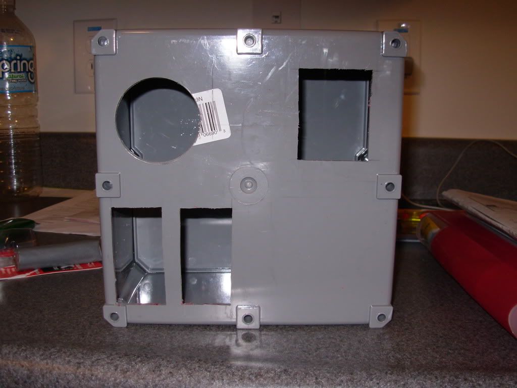
FYI, when wiring THIS box (8x8x4) you need to use 12awg wire where possible, only use the 10awg where needed.(ie. the 240VAC switch and outlet) The box is tight, this wire is rigid, do yourself a favor!
Enter your email address to join: