Basic SSRV Controller build HELP~!

Homebrew Talk - Beer, Wine, Mead, & Cider Brewing Discussion Forum

Help Support Homebrew Talk - Beer, Wine, Mead, & Cider Brewing Discussion Forum:

This site may earn a commission from merchant affiliate links, including eBay, Amazon, and others.

NFryan

Well-Known Member
Joined
Nov 21, 2012
Messages
223
Reaction score
17
Just quick question. Im building a very basic controller with a 40a SSRV from auberins with rheostat. I started my build based on another forums members basic schematic. My only question about it before I make my connections is why don't both hot wires on the schematic go to the relay? and should they?

sch.JPG

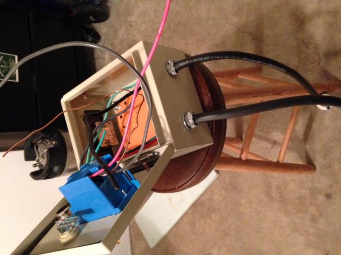
I am going to be using 1 - 5500 w 240v element. I have a 30a gfci breaker which was installed in my panel and tied to a 4 prong dryer outlet. Below is my current controller I am putting together. Please someone let me know if I should have both hot legs going into the relay and then out to the element..

[/ATTACH]
 

Attachments

  • IMG_1901.jpg
    IMG_1901.jpg
    39.1 KB · Views: 319
  • IMG_4016.jpg
    IMG_4016.jpg
    47.7 KB · Views: 254
I don't believe you have a 220V dpst switch currently. I would recommend that you use your lights witch to control the 120V coil on a 40A contactor (both legs) and then send one leg to the ssr as you have shown in the diagram.
 
MadGus said:
I don't believe you have a 220V dpst switch currently. I would recommend that you use your lights witch to control the 120V coil on a 40A contactor (both legs) and then send one leg to the ssr as you have shown in the diagram.

I DO have a 240 v 30 amp dpst on off switch.
 
MadGus said:
I don't believe you have a 220V dpst switch currently. I would recommend that you use your lights witch to control the 120V coil on a 40A contactor (both legs) and then send one leg to the ssr as you have shown in the diagram.

What I'm saying is can I take both hot legs out the switch and put them to one terminal on the ssrv. Then have 2 hot wires out the other terminal to the element?
 
+1 bobby

I looked at your pics earlier, and saw what looks like a regular household light switch, which is what prompted my comment. Is your dpst the on the bottom middle of your control panel face?

Either way, I would be hesitant to route 220v to something I was going to touch. Would still recommend a 40a contractor with a 120v coil controlled by a switch.
 
Bobby_M said:
If you tied both of your hot terminals together, your breaker will trip immediately due to a 240v dead short. It's similar to wirenutting a hot and neutral together on 120v.
So I'm ok to wire it based on the schematic at 240v? No issues burning the coil out early due to one the hot leg going directly to the element and not ssr?
 
ahhh... your rheostat is the knob on the bottom... should have guessed that.
 
Your original drawing is correct, and no you're not going to burn out your element prematurely. The reason is, a 240 volt circuit operates differently than 120 volt circuit. In a typical 120 volt circuit the current flows from the hot leg to the neutral. In a 240 volt circuit the current flows from one hot leg to the other hot leg. Which allows you to use a single SSRV to control the current flow. The SSRV opens the path of current flow between the two hot legs.
 
Your original drawing is correct, and no you're not going to burn out your element prematurely. The reason is, a 240 volt circuit operates differently than 120 volt circuit. In a typical 120 volt circuit the current flows from the hot leg to the neutral. In a 240 volt circuit the current flows from one hot leg to the other hot leg. Which allows you to use a single SSRV to control the current flow. The SSRV opens the path of current flow between the two hot legs.

Another question... So I have a gfci breaker wired to a 4 prong dryer outlet.. In my first pic the left cable on the control box is the 4 wires coming in from the 4 prong dryer outlet... The right wire is 3 wire cable coming out to a 3 prong 30a twist lock connector (which is what the element uses 3 wire 2 hot and a ground)..

My question is... the schematic doesn't account for the neutral wire (white)? Where do I connect it to? As of now I have a black and red the 2 hot leads going to the on off switch, and the green ground going to the on off switch, ssrv, out to the 3 prong and the metal housing.

I'm just not sure where the neutral goes in all this.


Any help would be appreciated.
 
The neutral would be used if you want to run any 120v devices out of this box.

Ahhh I see... So I can just cut the incoming white netutral and cap it with a wire nut and some electrical tape and leave it alone then?
 
So I completed my basic setup and took it for its maiden voyage 2 weeks ago. Everything worked great and I am up and brewing again. Thank you all for the help and quick responses! These pics below were from the initial testing.

1509876_10153657150340055_1236528561_n.jpg

562003_10153657150465055_905002221_n.jpg

1517473_10153657150685055_533983206_n.jpg
 
Back
Top