Arduino controlled fermenter questions

Homebrew Talk - Beer, Wine, Mead, & Cider Brewing Discussion Forum

Help Support Homebrew Talk - Beer, Wine, Mead, & Cider Brewing Discussion Forum:

This site may earn a commission from merchant affiliate links, including eBay, Amazon, and others.

eaglerisingbrew

Well-Known Member
Joined
May 14, 2014
Messages
64
Reaction score
6
Hi all,

I am building a fermenter that is controlled by an Arduino Uno. I have already swapped out relays once as I thought they weren't happy in a humid environment and were failing to turn off the fridge compressor. In the mean time, I am having the same problems with new relays. Obviously not the issue this time. www.eagle-rising-brewery.com shows the set up as it currently stands...

Question - Is anybody else having issues controlling a fridge? What did you do to overcome the issues?

Another question - does anybody have code out there they would be willing to share for an Arduino PID? Thanks.
 
OK need some more information, what relays are you using?

As for arduino code, I use the arduino pid library, lots of documentation for it.
 
Are they mechanical relays? and if so do they have a surge supression diode to reduce the effect of turning of the inductive device? If they don't I would look to see if that is your problem or use SSR to do the switching.
 
Yes, they are mechanical relays. They are a four-relay board from Sainsmart. I tried to use SSRs but the voltage requirements were to high for the Arduino pins. Do you know of any SSRs that would function properly at the 20mA level that the pins put out?
 
OK need some more information, what relays are you using?

As for arduino code, I use the arduino pid library, lots of documentation for it.
I will check out the Arduino PID library and see if that works for my project.
 
Yes, they are mechanical relays. They are a four-relay board from Sainsmart. I tried to use SSRs but the voltage requirements were to high for the Arduino pins. Do you know of any SSRs that would function properly at the 20mA level that the pins put out?

Most SSR I have seen are driven by a IR LED, so I would imagine you could actually drive it straight from a Arduino output pin. looks like the input current is 1.6mA @ 5Vdc - http://www.crydom.com/en/products/catalog/1_dc.pdf
 
I use mechanical relays, but use a transistor to drive the relay, check out this link : https://www.sparkfun.com/tutorials/119
SSRs will work but I prefer mechanical relays for this kind of application, they are cheaper, smaller and fail safe typically. You don't want to switch the fridge on and off too fast anyway, I have a 10 minute minimum on/off time on mine.
 
You should look into the diode thing , when you drive something inductive like a compressor and the relay try to stop it, the motor in the compressor will try to maintain the voltage and it will build an arc between the 2 contacts of your relay and with some time, weld them together.
 
Most SSR I have seen are driven by a IR LED, so I would imagine you could actually drive it straight from a Arduino output pin. looks like the input current is 1.6mA @ 5Vdc - http://www.crydom.com/en/products/catalog/1_dc.pdf

I have tried driving a few different SSRs directly from the arduino. The ones from auber instruments work fine but others require a transistor to drive enough current. In particular I just got some from ebrewsupply.com that can't be driven directly from the arduino.
 
I use mechanical relays, but use a transistor to drive the relay, check out this link : https://www.sparkfun.com/tutorials/119
SSRs will work but I prefer mechanical relays for this kind of application, they are cheaper, smaller and fail safe typically. You don't want to switch the fridge on and off too fast anyway, I have a 10 minute minimum on/off time on mine.

I have a three minute delay on mine. I have been concerned that I may be damaging my compressor at that delay so maybe I will also kick mine out to 10 minutes.

eaglerisingbrew - www.eagle-rising-brewery.com
 
You should look into the diode thing , when you drive something inductive like a compressor and the relay try to stop it, the motor in the compressor will try to maintain the voltage and it will build an arc between the 2 contacts of your relay and with some time, weld them together.

I just checked the Sainsmart 4-channel relay borad schematic and there is no diode/snubber on the output side. I think this is were you need to investigate first. Or buy one of their SSR boards, the 2A ones should be enough for a fridge compressor (anyone want to put their input into that comment?)
 
I just checked the Sainsmart 4-channel relay borad schematic and there is no diode/snubber on the output side. I think this is were you need to investigate first. Or buy one of their SSR boards, the 2A ones should be enough for a fridge compressor (anyone want to put their input into that comment?)

I have a Sainsmart SSR board but my concern is the draw. According to the sticker inside the fridge, the compressor pulls 7A. It is an older refrigerator...

www.eagle-rising-brewery.com
 
I always size my relays larger than the circuit is fused. A standard outlet is supposed to be fused at 15 amps (or at least is rated at 15 amps). My relays are rated at 30 amps (250 vac). Mechanical relays of this size are not much more than smaller ones. Overrating the relay should prolong the life, and just makes me feel safer. Relays, diode and transistor are approximately $6 plus shipping. I can replace the relay several times at that cost compared to the cost of a SSR. this is the one I use :http://www.digikey.com/product-search/en?WT.z_header=search_go&lang=en&site=us&keywords=G8P-1A2T-FDC5-ND&x=0&y=0&formaction=on
 
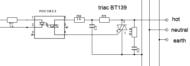
Why not make the SSR yourself? Use an opto coupler/driver to drive a triac with your Arduino.
See schematic diagram attached. The MOC3023 doesn't need much current. The BT139 can drive 16 AMP. A fridge has a high inrush current, but a BT139 is more than enough.

Input on the left, output right ;-)

Have a look at the datasheets for details on the snubber network (C's and R's) surrounding the triac and MOC. The datasheet of the MOC from Fairchild has examples. The values in my schematic are not correct, I didn't come to change them when making my PCB board ;-)
The input resistor (R7) will be somewhere in the range of 200-500 ohms

SSR.png
 
Back
Top