A heating element mystery.............

Homebrew Talk - Beer, Wine, Mead, & Cider Brewing Discussion Forum

Help Support Homebrew Talk - Beer, Wine, Mead, & Cider Brewing Discussion Forum:

This site may earn a commission from merchant affiliate links, including eBay, Amazon, and others.

CanadianNorth

Well-Known Member
Joined
Aug 24, 2009
Messages
119
Reaction score
0
Location
Newfoundland, Canada
I have been running my own little 'electric' brewery for a couple of years.

My kettle has a 5500 watt 220v element in it, and I would typically bring my wort to a boil, then simmer at 40%.

Recently, i noticed that it took much longer to bring my wort to a boil, and my 'simmer' required closer to 75-80% heat.

I did a test through beertoolspro, and it seems like my element is putting out 1800-2300 watts...........

I'm wondering what happened!!!! If I was somehow running 120v through the element I should only get 1/4 power, i seem to have 1/2 all of a sudden......

I've never seen this before, any suggestions?

thanks
 
Ha ha,

I wish it were that easy!!!

It's definitely one 5500 element.
My element is run by an Auber PID that feeds two solid state relays. I did replace the two solid state relays (one for each line of the 220) recently, but can't see how that would affect anything.
 
I just did, it's 10.5 ohms.

10.5 ohms translates to 23 amps at 240v, 23 amps @ 240v converts to 5500 watts, roughly.


so ... it may be the original power source? possible..........
 
Yep, 10.5 ohms is correct for a 5500w element. Maybe you hooked the system up in a 120v configuration when you changed out the SSRs?
 
The mystery deepens.

I checked the power output to the plug (the kettle has a short cord on it with a 4 prong 220v 30a plug). The output is reading 241v.

There is a bit of build up on the element itself, but I can't see that cutting the power in half.
 
Ha ha,

I wish it were that easy!!!

It's definitely one 5500 element.
My element is run by an Auber PID that feeds two solid state relays. I did replace the two solid state relays (one for each line of the 220) recently, but can't see how that would affect anything.

Why did you go with a relay for each hot leg? Most designs just use one relay on one leg.

Brew on :mug:
 
well, it's an inexpensive component and most SSR's, when they fail, will fail open. it's simply an additional safety component to prevent boilovers.

Makes sense. Thanks. Do you drive them with the same PID output, or a different output for each?

Brew on :mug:
 
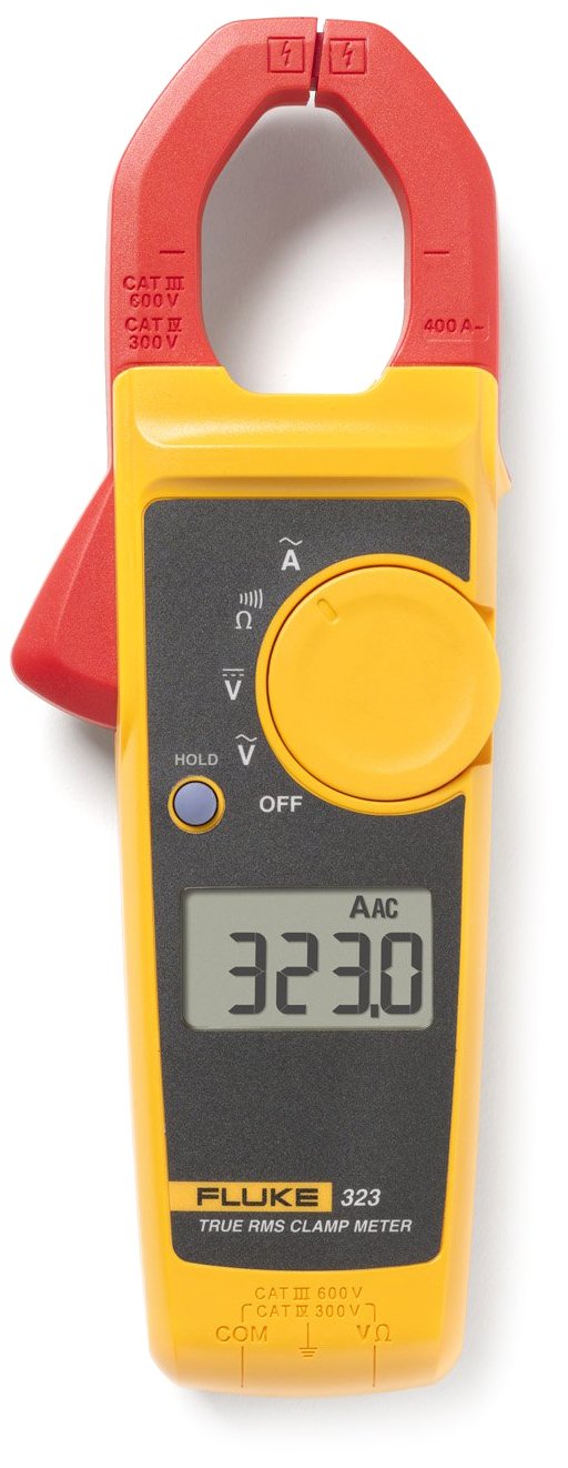
Did you measure 241V under load? Whatever the answer turn the heater element on and measure the voltage between the upstream (input) sides of the two SSRs. Now measure the voltage between the downstream (load sides) of the SSR's (looking for voltage drop across the SSR's here). Get a clamp-on ammeter ($60 at Canadian Tire) and measure the current drawn by the heater when it is energized (resistance changes with temperature so the cold ohmmeter reading is only approximately correct). The actual power delivered to the heater is the product of the voltage and current.

The effect of crud on the element would be reduced heat transfer from the element to the water/wort. This will cause the element to get hotter which in turn causes its resistance to go up with the result of less current draw and less electric power consumption.

If the heater is getting expected power when it is energized but less than rated power overall then the duty cycle from the controller is not what the dial says it is. Verify this by timing the on/off cycle (use the leds on the SSRs) with a stop watch. If you set 60% they should be on 6 seconds out of 10.


I'll check that. My metere was on the SSR output, without the element running. The lights on the SSR's are staying on 100% of the time with 100% power output.
 
I'll check that. My metere was on the SSR output, without the element running. The lights on the SSR's are staying on 100% of the time with 100% power output.

the output is 235V under load.

the performance is improved significantly with a thorough scrubbing of the element.....

I'll have to do a time/heat analysis later.
 
Maybe you can borrow a clamp-on ammeter and measure the current. Note that you have to grab exactly one conductor or the net current will always read zero. I've read mine and got the expected numbers (~23A).

61h18jO2mZL._SL1322_.jpg
 
Looks as if that's your explanation then. It would have been interesting to see how much the current changed between pre and post scrub though.

Tungsten filaments in incandescent bulbs change resistance by 10x when heated (resistance increases when they get hot). Put an ohm meter on the contacts at the base of a cold bulb and it won't make any sense when considering the wattage of the bulb.
 
Note that you have to grab exactly one conductor or the net current will always read zero.
Only if the sum of the currents in the two conductors is 0 i.e. equal and opposite as would be the case if you enclosed both wires to a heating element and there was no leakage of current through any other path. I know that is what you meant to say but you could, for example, use a clamp on meter to measure the imbalance between the two phases of a 120/240 subpanel or system by enclosing the red and the black wires. Or you could enclose just the neutral (white) and get the same answer.

In the present case it might be a good idea to enclose both wires to be sure that the current imbalance is indeed 0 and that, therefore, there is no leakage.
 

Latest posts

Back
Top