2x 4500W elements?

Homebrew Talk - Beer, Wine, Mead, & Cider Brewing Discussion Forum

Help Support Homebrew Talk - Beer, Wine, Mead, & Cider Brewing Discussion Forum:

This site may earn a commission from merchant affiliate links, including eBay, Amazon, and others.
Could somebody explain to me the way the emergency off switch works in the diagram by P-J? if it is being fed 120 VAC, and the switch is closed, wouldnt that cause (120/2000)A to be drawn through those resistors to ground? .06A is what i get which would not blow the fuse but would cause 7.2 watts to dissapate across the two 1kohm, 1 watt resistors. Wouldnt this overheat those two resistors?

Or is it a non-issue becasue the current will only run through that line momentarily until the breaker trips?

In the foot notes of the diagram:
EPO - wired to trip GFCI main circuit breaker with small leakage current. ( 0.06A)
Which will only happen for a few milliseconds while the GFCI trips. It is exactly the same as if you press the test button on the GFCI breaker. BTW: at 0.06A of power that is drawn (7.2 watts), do you really think a few milliseconds of that power draw would harm a pair of 1W resistors? Really???

I guess I should quit making diagrams anymore for the brew community.

...

Edit: (deleted) - Nevermind. I will only come out to be understood the wrong way.!
 
I had never thought of intentionally tripping the GFCI for E-stop functions. That's a good idea. I was planning on using a contactor, but this looks like a cheaper/easier method.
 
I had never thought of intentionally tripping the GFCI for E-stop functions. That's a good idea. I was planning on using a contactor, but this looks like a cheaper/easier method.
Just to let you in on a 'little' of my thinking - When something happens that is somewhat potentially catastrophic, I thing it would be wise to kill all of the power to your brew area. Smoke comes out from 'something'. A relay circuit in your CP does not prevent power from being delivered to it. You trip "your" circuit and smoke continues.

Now what? Run 50' - 100' to the mains panel to cut the breaker. Or run a good distance to pull a plug (dangerous by its self) delivering power to your brewery?

As I said before, I think I'm done....
 
In the foot notes of the diagram:
Which will only happen for a few milliseconds while the GFCI trips. It is exactly the same as if you press the test button on the GFCI breaker. BTW: at 0.06A of power that is drawn (7.2 watts), do you really think a few milliseconds of that power draw would harm a pair of 1W resistors? Really???

I guess I should quit making diagrams anymore for the brew community.

...

Edit: (deleted) - Nevermind. I will only come out to be understood the wrong way.!

Well, do you think i would have asked if i didnt find it questionable? Why, when dealing with a cheap component such as a resistor, would you use one that is not rated for at least the amount of current you fully expect it to handle? why not a single 2k 10W resistor?

I know this is not a big deal, but i dont think myself and the rest of this community need our hands slapped for asking a valid question. And by the way, i very much appreciate the diagrams and info that you have given thus far and hope that you will continue to post them!
Go do it your way and, like I said, "I think I'm done.... "
 
A low power resistor is perfectly fine for this use, do you think the test button in your GFCI outlet uses a big expensive 10W power resistor to do its job? Not a chance. PJ's design looks sound to me.

I do however think that asking questions is the best way to learn.
 
It's exactly what I plan to do, but when I mean plan, I mean, it is my high level intention at this point. I'm going to put two 5500w elements in the HLT and two 5500w elements in the BK. I'll use an interlock so that I can only run either two in the HLT, two in the BK, or one of each at the same time. Yes, it's pure overkill but in the end it's for time savings and scalability. Right now it's a 10 gallon system but if I ever go to 15 or 20 in the future, it's just a vessel change out not a full system overhaul.

I wanted to bump this thread and see if anything ever came from your planning here Bobby. I am throwing around a few ideas for my system and was thinking of integrating 4 5500W elements in the manner where you described so that only 2 could ever be on at the same time. Probably way overkill like you stated but it seems like that what we are good at on this forum. :mug:

Has anyone seen any other threads on this or anyone that has actually done this yet? Like I said I am in the early planning stages but would like to start working towards this soon. Thanks for any info

Pat
Here is a diagram that is partway there. It would require some selector switch modifications to achieve what you are looking for (being able to select any combination of 2 elements). The diagram is for 4 - 5500W elements using a 60A feed. With 4500W elements a 50A feed would be A-Ok.

Please let me know what you think.

As always - click on the image to see a full scale diagram printable on Tabloid paper (11" x 17")


Thanks P-J!! I will take a look at this this afternoon and Im sure I will get back with you on it. Im in the prelim stages and just started a thread about this kind of setup. Thanks for your quick response. Look forward to chatting with you more about this.

Pat
 
Thanks P-J!! I will take a look at this this afternoon and Im sure I will get back with you on it. Im in the prelim stages and just started a thread about this kind of setup. Thanks for your quick response. Look forward to chatting with you more about this.

Pat

Pat,

I did a drawing for a mod to the posted diagram that would allow you to control the elements as you want to. Both ON in the HLT or the BOIL. Or 1 ON - one each in the HLT and BOIL. Selector switch X accomplishes that for the mission.

a11c-RM-SYL.jpg

I hope this makes sense.
 
I think the selector switch can be simplified a bit. The HLT enable and BK enable push buttons are controlling the pairs of contactors associated with each vessel type. If you want to be sure the HLT is OFF OFF, you disable the contactors for those vessels.

The requirement of "any two elements" could be modified as follows. Element/SSR 1 is in the HLT and always being driven off PID1. Element/SSR 4 is in the BK and is always being driven off PID2. Elements/SSR #2 and 3 are in the HLT and BK respectively but are mutually enabled via a double pole double throw selector labeled "power boost" with positions HLT and BK. On the HLT side, PID1 control is connected to SSR 2. On the BK selection side, PID 2 control is connected to SSR 3 (mutually exclusively). You could also use a center off position if you didn't want either vessel to have the extra 5500w at any given time.

To summarize this thought a bit, the selector doesn't have to influence the contactors. I suppose there is a chance for one SSR to fail closed while both HLT and BK contactors are enabled which would fire 3 elements at the same time, but the breaker will deal with that failure.

Is there anything wrong with that?
 
Thanks P-J,

So is this basically two of the selector switches in line. So the first switch chooses HLT, Off or BK. Then Second switch would be Element combinations?. So if I had switch 1 on Boil and Switch 2 turned to the right I would be using Elements 1,4 and to the left would be elements 4,3. And if I had first to HLT then left would be 1,2 and right would be 2,3?Just making sure Im picking up what you are putting down.

Thanks again for your expertise. You are the man!!
 
I think the selector switch can be simplified a bit. The HLT enable and BK enable push buttons are controlling the pairs of contactors associated with each vessel type. If you want to be sure the HLT is OFF OFF, you disable the contactors for those vessels.

The requirement of "any two elements" could be modified as follows. Element/SSR 1 is in the HLT and always being driven off PID1. Element/SSR 4 is in the BK and is always being driven off PID2. Elements/SSR #2 and 3 are in the HLT and BK respectively but are mutually enabled via a double pole double throw selector labeled "power boost" with positions HLT and BK. On the HLT side, PID1 control is connected to SSR 2. On the BK selection side, PID 2 control is connected to SSR 3 (mutually exclusively). You could also use a center off position if you didn't want either vessel to have the extra 5500w at any given time.

To summarize this thought a bit, the selector doesn't have to influence the contactors. I suppose there is a chance for one SSR to fail closed while both HLT and BK contactors are enabled which would fire 3 elements at the same time, but the breaker will deal with that failure.

Is there anything wrong with that?

Thanks for weighing in Bobby!! I couldnt believe when I was looking around and saw you had talked about this type of setup in the past. You validated a little bit of my craziness I think. Now hopefully I can make this thing happen.

I like your wording of "power boost". looking forward to seeing what comes from this discussion. Thanks again!!

Pat
 
Nevermind.. I'm completely off here. For some reason I was thinking any THREE elements. You'd still want a max of 2 but it would be either 1+2, 3+4 or 2+3. The reason I didn't pursue the design yet is because I may be going with a Speidel Brewmeister clone instead.

There should be several ways to implement the choice of those three states. I think it's mostly driven by how you think of the process. Do you want to be able to only have ONE element on at any given time. For example, during the boil is there any reason not to be PWM'ing 11kW? I think so because you will probably get some pulsing when it's 11kW on or off.

That would modify the states to 1+2, 2+3, 3+4 or just 4.

How about two 3-pos selector switches affecting the contactors, one for HLT and one for BK. The three positions would be labeled On (or ONE), OFF, Both.

HLT on turns on just one HLT element. Off obvious, Both turns on both.

BK "on" turns on just one BK element. Off obvious, Both turns on both.

How to prevent more than two to energize at a time (in theory):
The input to the HLT selector would route through an NC contact block under the "both" position of the BK selector. So, when the HLT is set to both, it deactivates power to the BK selector altogether. The opposite happens for the BK selector.

You could set both to off (center position). You could select ON or "ONE" on the HLT, HLT and BK, or just BK. Once you set either one of those selectors to BOTH, only that device fires both. I'm pretty sure this could be done with enough contact blocks, I just haven't figured out exactly how many. They're cheap enough.
 
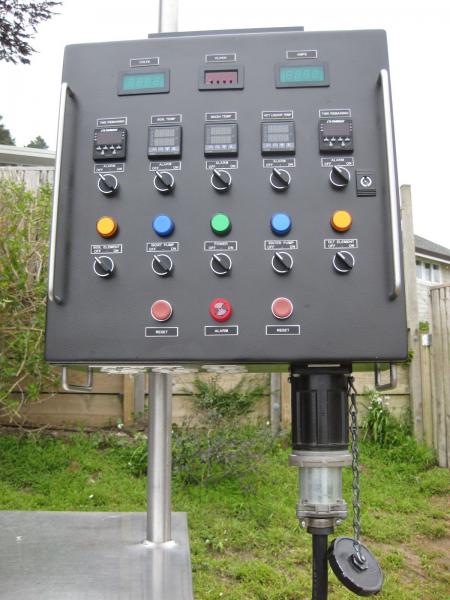
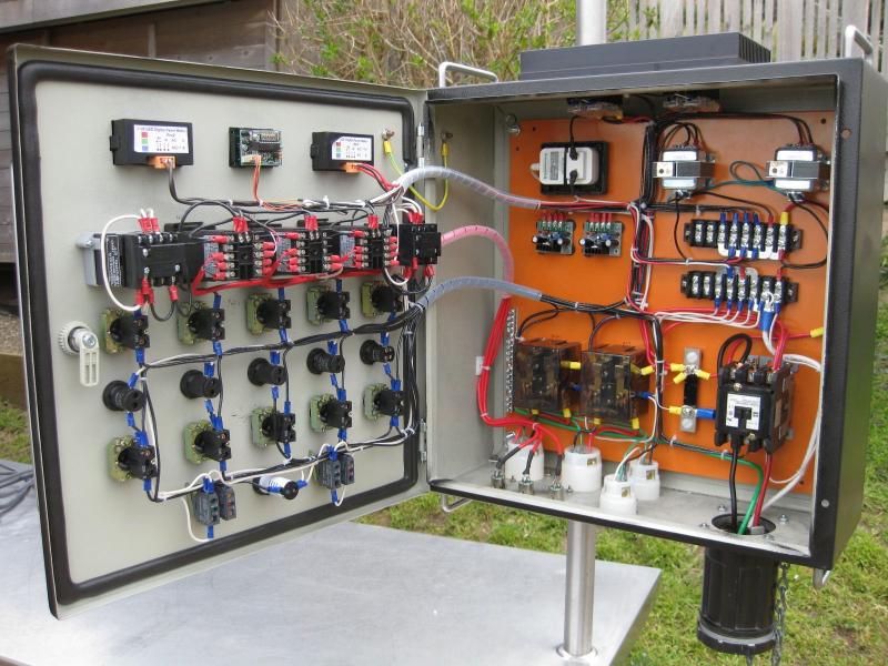
Just to continue the thread and offer another method (on the below pic's), just add another (2) relays and outputs and you can have your (4) 5500W heaters.
If interested, I can give you more details since mine is for back-back batches.

IMG_3160.jpg


IMG_3157.jpg
 
I am working on a build that has very similar goals to this set up so I just subscribed to it and hope to contribute to it more soon.

I have two rigs in the works, one will be a 3 keggle set up, and the other will be a three 55 gallon drums set up.

I want to be able to control both rigs with the same control box, but never at the same time.

my keggle setup will have 1 5500W element in both the HLT and the Boil Kettle

my 55 gallon drum set up will have 2 5500W elements in both the HLT and the Boil Kettle

my Keggle set up is currently functioning great off of propane.

I already have the 55 gallon drums, 6 5500W elements, PIDs, control box, lights, and a 60A spa panal

I am still trying to figure out where to source a bunch of the other equipment such as the heat sinks and relays. I also I wanna get a TIG welder

glad to see there are others attempting this too

and Sparky that looks Great
 
Old thread but I thought I'd chime in.

I'd be curious how many electric brew system builders have actually permitted and got an inspection on their system.
You don't have to since it's not hard wired (usually).

When I put the outlets and lights in my previous brewing room I went through all the proper electrical permitting to do this work. It included a 30A/240V dryer outlet.

All the inspector cared about was that the wiring and the things *attached to the house* were done to code.

The control panel (which he was indeed very curious about on a personal level) did not and does not factor in.

How you, the homeowner, want to use that outlet is up to you. You could plug something in that draws more current than the breaker/wiring/outlet are meant to provide. The inspector just wants to make sure that the breaker is properly sized so as to pop correctly without the wire frying if you were to do this.

...I felt the legality of such an installation should at least be brought up if something happened and an insurance company had to get involved.

That (IMHO) is the crux of it. Someone can use go past the 80% rule if they want, they should just be aware of it before building their setup. They should be aware and told that they've likely entered in a grey area as far as NEC is concerned if they ask. I think it's dangerous to recommend to people that it's fine to do without giving them the "but be aware that ..." speech. I get asked the question "can I use two 5500W elements on a 50A circuit" a lot and I simply mention that in some places (and depending on how you interpret the code), you shouldn't use more than 80% of rated capacity. I tell them to talk to their electrician and explain what they're doing to be sure. Give them the tools to make their own decision.

Kal
 
Back
Top