Need some LM317 Stir Plate Help!

Homebrew Talk - Beer, Wine, Mead, & Cider Brewing Discussion Forum

Help Support Homebrew Talk - Beer, Wine, Mead, & Cider Brewing Discussion Forum:

This site may earn a commission from merchant affiliate links, including eBay, Amazon, and others.

yukonhijack

Well-Known Member
Joined
Nov 19, 2011
Messages
139
Reaction score
11
Location
Albuquerque
I built my stir plate using the old pot/power switch, but the fan was too fast and was throwing my stir bar. I found some information on how to wire up the stir plate with a LM317 regulator circuit. I wired it up as I thought it was supposed to go, and while I get power, I get no spinning of the fan. I have been over the circuit a number of times but cannot figure it out!

Does anyone have a photo of their stir plate with the regulator circuit that they would share? I think if I can see how others have done it (possibly with arrows identifying the wires/leads), I would be able to put this one to bed. Any help is GREATLY appreciated.

Thanks,

Greg
 
I built mine based on the following:

http://www.stirstarters.com/instructions.html

I will try to remember at take a photo of and post the circuit I built (using some stripboard I had hanging around) this weekend . . . having a variable voltage output is very helpful in being able to dial in the speed at which you want to stir, and . . . It works great, but I think more important is the type of stir bar that you use . . . I have found that the octagonal bars with the raised center strip to be the most forgiving with regards to stability.
 
The fan my respond better to pwm. A lot of people feel pwm is overkill but I did it anyway for grins.

Can you post the circuit that you used?
 
That looks like the same circuit mainaic linked to. Did you double check to make sure that your regulator isn't backwards? Also, have you put your voltmeter on the output to see what it's actually doing. Does the fan make a stall noise or any kind of noise at all? A picture of what you have would be helpful.
 
Here is a quick pic (I am in the middle of also brewing a Green Flash IPA).

On the left is the Pot. The Right switch is oriented so the left lead is ground, middle is load, and right is power.

20141219_200055.jpg
 
What are the resistor values for the fixed and potentiometer resistor?

The pic doesn't clearly show how the potentiometer is wired, which can be critical.

Do you have a voltmeter?
 
No, sadly I have no volt meter. I just realized how bad that photo is. I will post up some that are clearer.

The resistor is a 330 1/2 watt, and the pot is the one from Radio Shack (25 ohm) that others have used.
 
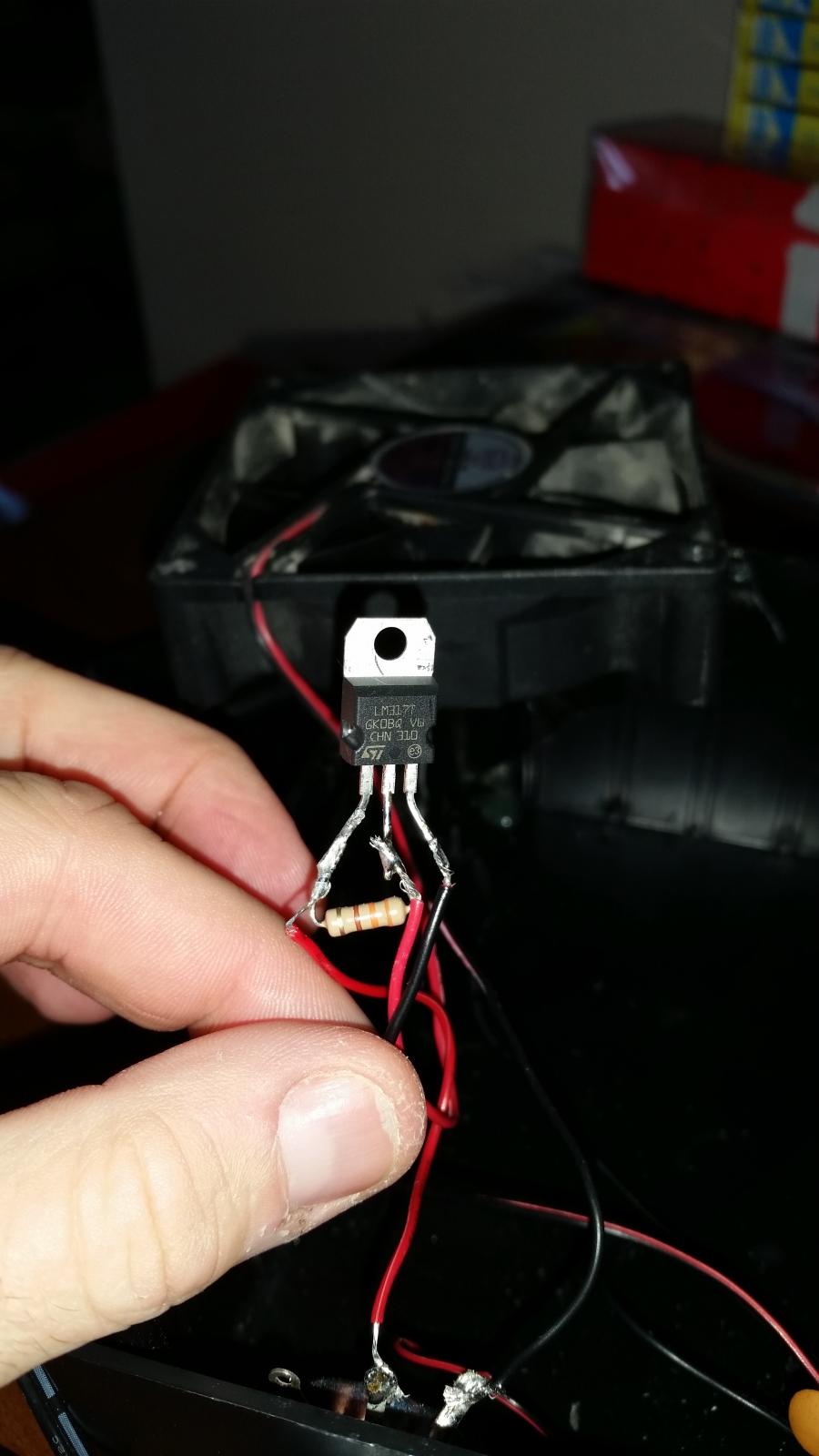
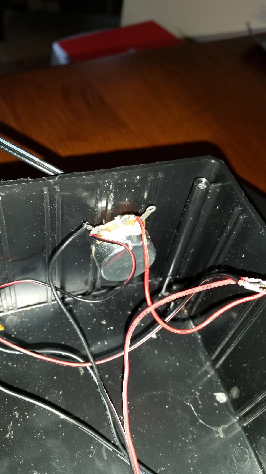
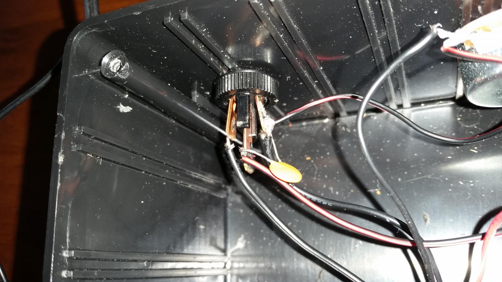
OK, here is what I have.

Power Switch Config:
Incoming power supply hot wire to power pin
Center pin to right pin of LM317
Incoming power supply ground wire to ground pin
Jumper wire to right leg of pot
.1 uf cap jumped across load pin and ground pin

Pot
Middle leg to left leg of LM317
Left Leg to black fan wire
Left leg jumped to ground on power switch

LM317
Left leg to middle leg of pot
330 ohm 1/2 watt resistor jumping left and middle legs
Middle leg to red wire of fan
Right leg to middle pin of switch

2014-12-20 10.00.53.jpg


2014-12-20 10.01.29.jpg


2014-12-20 10.01.45.jpg
 
...The resistor is a 330 1/2 watt, and the pot is the one from Radio Shack (25 ohm) that others have used.
That combination of resistances will only result in a maximum of 1.4v to the fan. The 25ohm pot is used in the pot/fan in series circuit that others have used. The potentiometer for an LM317 circuit must be selected in conjunction with the fixed resistor value to create a useful output voltage. It is also very useful to insert a fixed resistor in series with the potentiometer which sets the minimum voltage out above 0.

I'll offer up a suggestion with parts from radioshack, assuming a 12vdc input and a 12vdc fan:

2.2k ohm fixed resistor between adj and Vout LM317pins.

5k ohm linear taper potentiometer.

4.7k ohm fixed resistor in series with the potentiometer. Attach to ground and one outside leg of the potentiometer. Do not connect a ground to the potentiometer.

Connect the center leg of the potentiometer to the adj LM317 pin. Jumper the unused potentiometer outside leg to the center leg.

This combination of resistances should result in 4 to 6.8 vdc, Vout, applied to the fan as the potentiometer is adjusted from min to max.
 
Thanks for that response. After rubbing my head, I went to the garage and found a lower power wall wort, which seems to work fine. I don't have any speed control (just wired it direct to the power switch), and while it is not as powerful as with the previous plug, it is sufficient.

Thanks!

Greg
 
Also, you may want to keep an eye out for the LM317 getting hot. The example I used recommended using a heat sink. I installed it since the LM317 can generate some heat while in use.
 
Back
Top