HOWTO - Make a BrewPi Fermentation Controller For Cheap

Homebrew Talk - Beer, Wine, Mead, & Cider Brewing Discussion Forum

Help Support Homebrew Talk - Beer, Wine, Mead, & Cider Brewing Discussion Forum:

This site may earn a commission from merchant affiliate links, including eBay, Amazon, and others.
Status
Not open for further replies.
Just to see what I would get... I took a reading across the grd and 5v leads. It is reading 1.1 v. If I take the reading on the wires feeding the sensor I get 5.0v. Is this normal to get this low reading on the leads of the Ds18b20?


I tested mine by placing the sensor and resistor directly into the arduino pins. I would try that to eliminate any extra unnecessary connections.
 
If the sensor is faulty then it may have an internal short. This would cause lots of current to flow which would cause a voltage drop and local heating.

So, it could be a dud sensor. Very rare, but not impossible. Do you have another?
 
Just to see what I would get... I took a reading across the grd and 5v leads. It is reading 1.1 v.
If I take the reading on the wires feeding the sensor I get 5.0v. Is this normal to get this low reading on the leads of the Ds18b20?

I have no idea how you got 1.1v between GND and 5V - or how that's different from "the wires feeding the sensor". Aren't they the same wires?

Anyway...if you had an oscilloscope you'd see the one-wire bus state toggles between 5V (the pull-up resistor) and GND when the system is running...

Cheers!

I should say that when I got the 1.1 v I had the sensor hooked in the circuit. When I got the 5v I had removed the sensor. It immediately drops to 1.1 as soon as I hook the sensor in the circuit.
 
I tested mine by placing the sensor and resistor directly into the arduino pins. I would try that to eliminate any extra unnecessary connections.

I do have another sensor. I just am wondering if there is any way to test and make sure the leads are in the standard location? I need the remaining sensors and would hate to fry another.
 
If the sensor is faulty then it may have an internal short. This would cause lots of current to flow which would cause a voltage drop and local heating.

So, it could be a dud sensor. Very rare, but not impossible. Do you have another?

See my previous post.. I quoted the wrong post.
 
I should say that when I got the 1.1 v I had the sensor hooked in the circuit. When I got the 5v I had removed the sensor. It immediately drops to 1.1 as soon as I hook the sensor in the circuit.

Got it. That sensor has gone to Digital Heaven.

I hooked up a known-good ds18b20 with the power and ground leads swapped and promptly fried it.
When I felt the metal case it was hot. It never worked again...
 
Got it. That sensor has gone to Digital Heaven.

I hooked up a known-good ds18b20 with the power and ground leads swapped and promptly fried it.
When I felt the metal case it was hot. It never worked again...

I figured it was a goner.. Do you know of any way to test which lead is is the positive and grd before I stick it in and hook it up? This one was hooked up in the normal Ds18b20 pin config. I have a meter of that would help in any testing.
 
Well I just tried using an ohmmeter going between the three leads in both polarities and there's really no process that could positively identify anything that way.

Did you mention the wire colors used? (I may have missed it)...

Cheers!
 
Well I just tried using an ohmmeter going between the three leads in both polarities and there's really no process that could positively identify anything that way.

Did you mention the wire colors used? (I may have missed it)...

Cheers!

I was using it direct in the breadboard. I posted a picture of the setup ac few posts ago this evening. In the picture the left pin was grd middle data and right 5v.
Thanks for checking for a hint of trying to identify!
 
Referencing this picture

attachment.php


you are correct: left to right the pins are GND, DATA, and PWR.

Or, should be, anyway...

Cheers!
 
I do have another sensor. I just am wondering if there is any way to test and make sure the leads are in the standard location? I need the remaining sensors and would hate to fry another.

Did you read my post? Sigh
 
Did you read my post? Sigh

I know the feeling. I did read your post but I need a little more info. What indications would I receive if I correctly have the grd and data connected in the test sketch? What is the test sketch? So I should connect the wires and resistor the exact same way except do not connect what is suspected to be the 5v lead? I just need a little more clarification. I really do appreciate your help on figuring this out!!
 
i have a raspberry pi with arduino uno, but when running the script starts and stops all the time. and in the lcd window it says "can not receive lcd text from python script"
Maybe this have been resolved in the thread but its a bit long :)
 
I know the feeling. I did read your post but I need a little more info. What indications would I receive if I correctly have the grd and data connected in the test sketch? What is the test sketch? So I should connect the wires and resistor the exact same way except do not connect what is suspected to be the 5v lead? I just need a little more clarification. I really do appreciate your help on figuring this out!!

The idea is to use his sketch to find the sensor in Parasitic Mode - so you only have to hook up two wires, with neither connected directly to 5V, and with the 4.7K pull-up always attached directly to the A4 pin (which is the only thing you know for sure at the start).

So, hook up one wire to A4, the other to GND, and run the sketch.
If the sensor isn't found, swap those two wires, test again.
Still not found, change out one of those wires for the third and test again.
Still not found, swap those two wires.

Eventually you'll hit the right pair of wires on the right two pins (A4 and GND) and the sensor will be detected in PAR mode. That means the unconnected wire is the VCC lead, and when you connect that to 5V the script should now see the sensor in non-Parasitic mode...

Cheers!

Thank you for the explantion! I just want to make sure I understand correctly. I have the data pin attached to the resistor. the other end of the resistor going to the a4 on the Uno. Then what I believe the grd pin attached to the grd on the Uno.

Do I connect the 5v line to the resistor as well? If not there where do I connect it? Or does it not get connected at all? I guess I am trying to figure where the power comes from if not the 5v. Maybe the a4 has a limited power it can provide through the data line?

Sorry for having to explain this so detailed. I am learning as I go on parts of this. This being that part. I have been researching and trying to understand both modes of this sensor to better help me troubleshoot.
Basically from what I understand I will keep trying different combinations of wires on leads until it finds it in PAR mode. I am guessing with only two wires you can not fry it so getting the wires on the wrong leads is not a big deal.
 
I've created a quick Arduino sketch to tell you what onewire devices you have connected, and if they are operating in parasitic power or not.

To use it, wire up the Ardunio with the onewire on pin Analog 4.

Include some extra libraries:

Sketch -> Include Library -> Manage Libraries
Install:
Onewire. (There is an Adafruit one, don't choose this)
DallasTemperature

Put the code into a sketch, then upload it. You can see the output by looking at the serial monitor (Tools-> Serial Monitor)


The code is here http://geordish.org/one.txt

edit: Moved code to a link

I'm guessing this is the sketch we are referring to. If there is another one please let me know. Thank you
 
Thank you for the explantion! I just want to make sure I understand correctly. I have the data pin attached to the resistor. the other end of the resistor going to the a4 on the Uno. Then what I believe the grd pin attached to the grd on the Uno.

Do I connect the 5v line to the resistor as well? If not there where do I connect it? Or does it not get connected at all? I guess I am trying to figure where the power comes from if not the 5v. Maybe the a4 has a limited power it can provide through the data line?

Sorry for having to explain this so detailed. I am learning as I go on parts of this. This being that part. I have been researching and trying to understand both modes of this sensor to better help me troubleshoot.
Basically from what I understand I will keep trying different combinations of wires on leads until it finds it in PAR mode. I am guessing with only two wires you can not fry it so getting the wires on the wrong leads is not a big deal.

Yes, the 5V needs connecting to the data line via a resistor for parasitic mode to work.
 
I created a quick draw up on fritzing to confirm I am doing this correct. I will connect the sensor pins to the data and grd leads. ( until I find the correct leads to give me results) I mainly want to make sure I have the powering to the sensor set up for parasitic mode.

View attachment 1463246403612.jpg
 
That looks correct - as long as your trial connections are to the columns with the green and yellow wires.

Do not connect to the column with the red wire 'til you have identified the vcc lead...

Cheers!
 
Yes, the 5V needs connecting to the data line via a resistor for parasitic mode to work.

In parasitic mode, the sensor draws the voltage it needs from the data line. So when using elkoe's wiring (without VCC) you are just making sure you have data and ground pins correct.

The brewpi software won't recognize any sensors wired this way.

Once you know you have DATA and GND correct, hook up the 5V line and you should be good to go.
 
i have a raspberry pi with arduino uno, but when running the script starts and stops all the time. and in the lcd window it says "can not receive lcd text from python script"
Maybe this have been resolved in the thread but its a bit long :)


You must read all 5976 pages of this thread before asking a question…


Jk. you are probably using safari or ie. in that case your browser is a dirty liar and there is nothing wrong with your setup. a few pages back there is a post referring to another post in this thread telling you how to remedy this issue, I simply do not use safari to show off my system. chrome or chromium will not give you this problem. if the problem persists then bring us your log files and we'll get to the bottom of this.
 
I have finished testing all possible combinations using 2 leads with grd and data. The sketch returns no devices detected in all possible combinations.

I always had one lead connected to nothing. I know in PAR it seems that the vcc lead is grounded as well. Should I have grounded the lead that was not connected? Except then I would really not be able to tell which is the VCC if that was the case.
 
I felt so close and thought it was pretty much figured out. But now it seems I have taken a few steps backwards. Thank you to everyone who is helping! We will get there!
 
You must read all 5976 pages of this thread before asking a question…


Jk. you are probably using safari or ie. in that case your browser is a dirty liar and there is nothing wrong with your setup. a few pages back there is a post referring to another post in this thread telling you how to remedy this issue, I simply do not use safari to show off my system. chrome or chromium will not give you this problem. if the problem persists then bring us your log files and we'll get to the bottom of this.


Thanks, been trying all day to fix that..:) but did not try another browser...
All good now...)
 
Posting this chart for a friend. He just set up his brewpi and is asking for help. He want's to know if this graph looks right.
13177209_10209906599448635_1504161774137192158_n.jpg
 
It almost looks like the fridge is hooked to the Heat relay.
Notice that the Fridge Setting is trying to go warmer at what appears to be the same point that the compressor turns on and drives the temperature down...

Cheers!
 
Hey there everyone.

Thanks again to FuzzeWuzze and and everyone who has had their hand in this. Just an amazingly fun, easy and cheap project (especially if you are willing to wait and order the parts directly from China at 20 cents on the dollar compared to Amazon).

This is my second build on this design. My first is to spec and uses a deep freeze. I am building the second one because I want to do some lagering. Tying up my system for 8 to 9 weeks is just too much for a 5 gallon batch. Seems crazy... Clearly, I need another one, right?

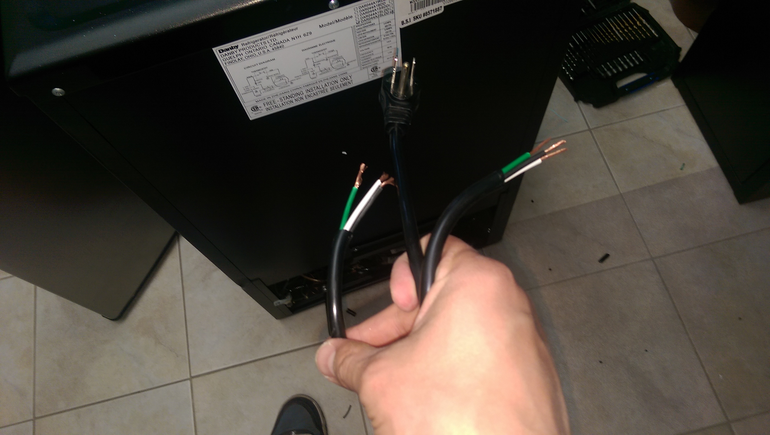
For this one I bought a 2 year old Danby DAR044A2SLDD (I think its a Costco model) on kijiji that had a malfunctioning thermostat. Got it for $60 CAD ($46 in greenbacks at time of post).

In a nutshell this build had me bypass the thermostat, forwent the outlets to direct wire everything in and drill a hole in the top of the fridge to run the temperature probes and power for the heater into it. I went through the top because there are a lot of guides on HBT for making this model of fridge into a keggerator. Seemed like the sweet spot to drill without damage as many have used it for a beer tower.

Pictures of the process below -

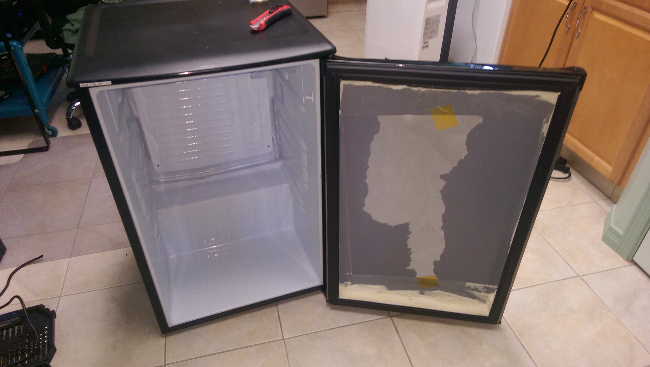
Cleaned up and all of the door storage/plastic removed. Ready for construction! (I removed all of the insulation because I want to fit a big mouth bubbler in it. I am running tests currently to see the power loss. If required, I will insulate the outside of the door to reduce energy loss.)
L8Q6MCQ.jpg


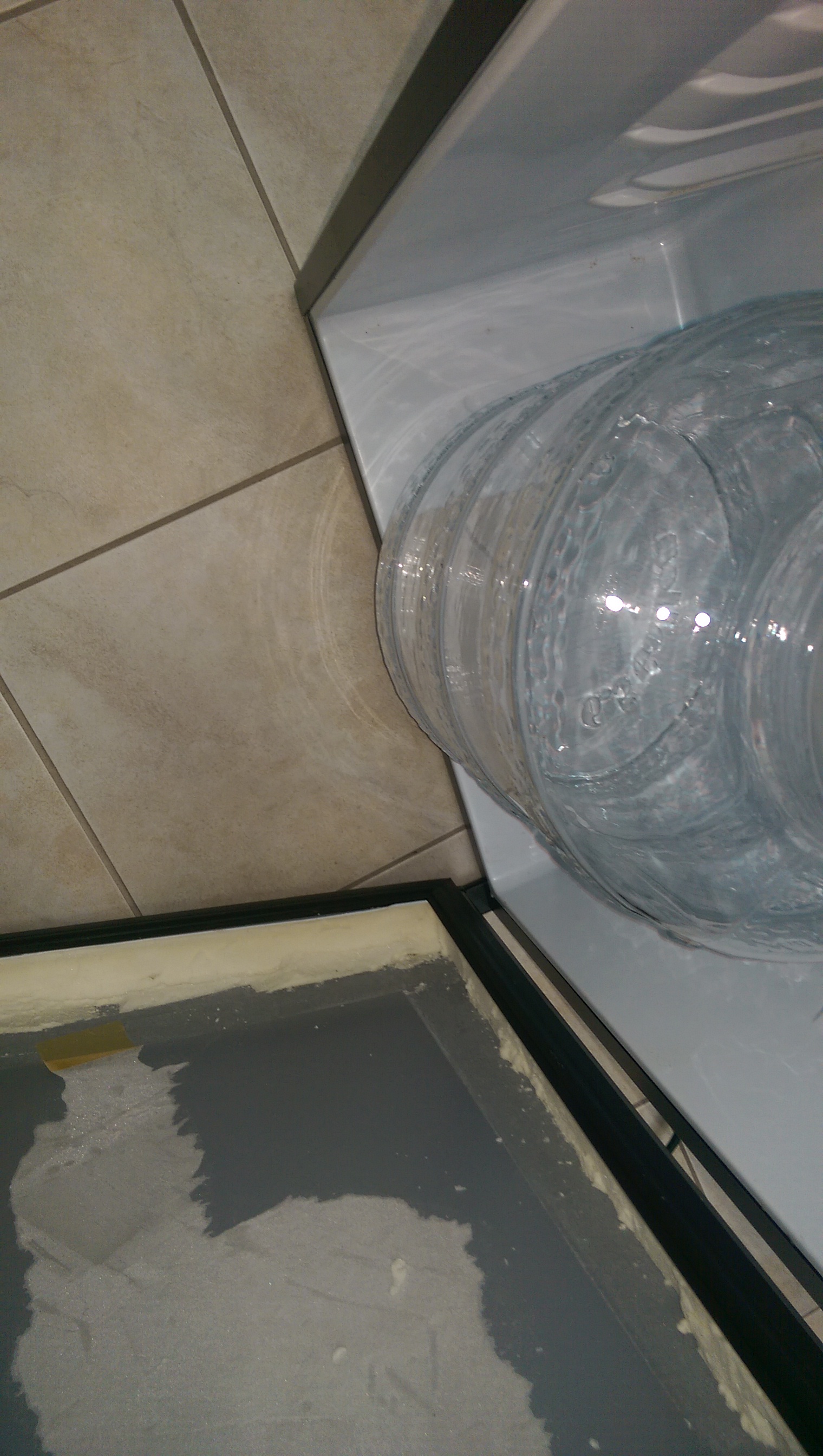
The big mouth bubbler issue... With the insulation carved out the door closes comfortably with the 6.5 gal big mouth bubbler in it.
uAFkNVo.jpg


Ready to start construction.
1Eo3iPX.jpg


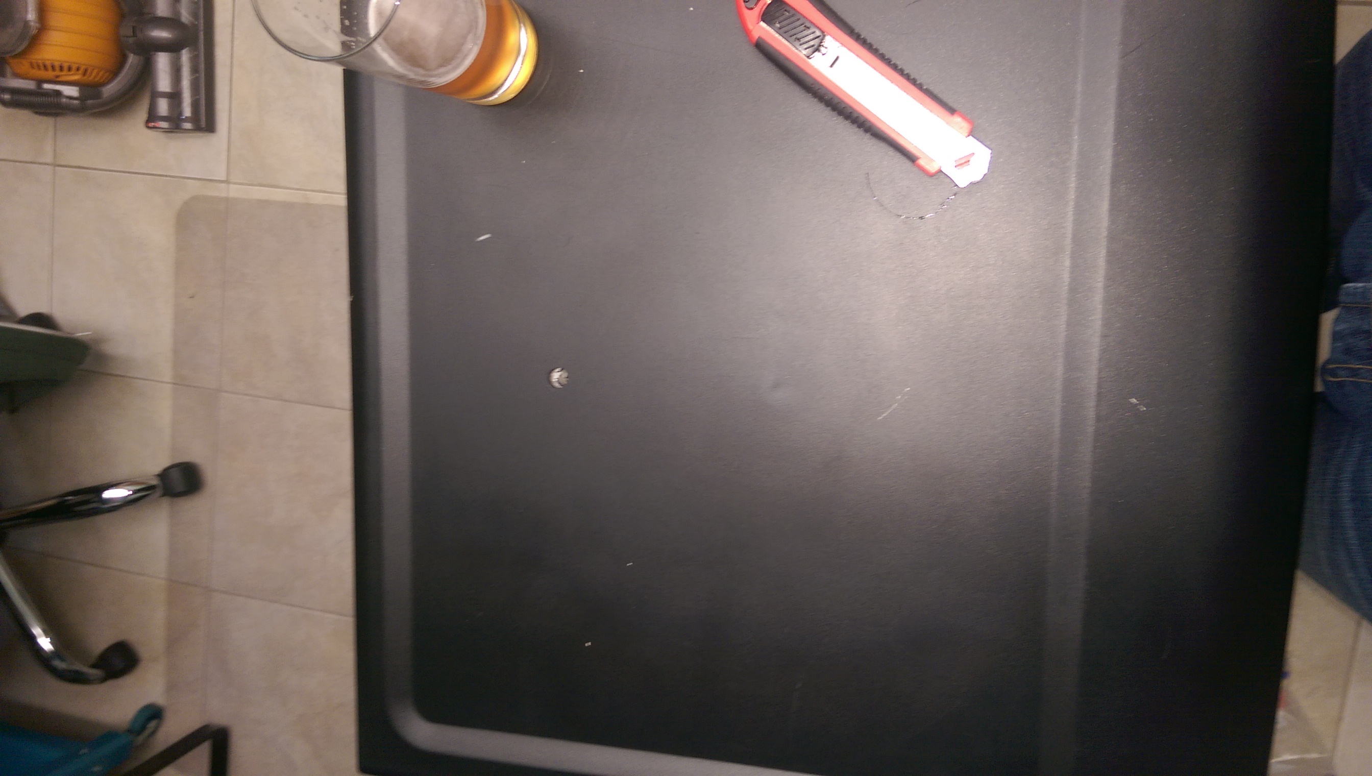
This is the hole I punched in the top to run all the cables into the chamber.
xC1YfAT.jpg


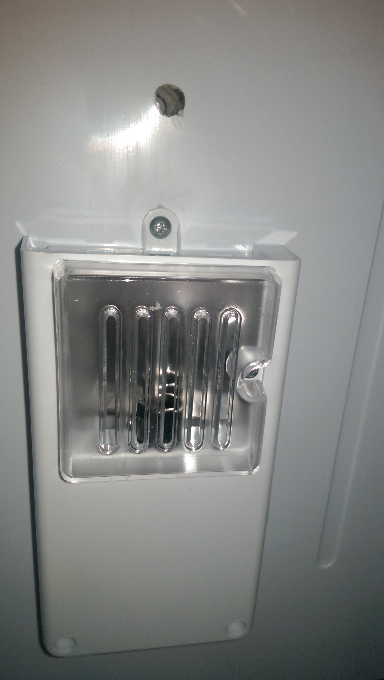
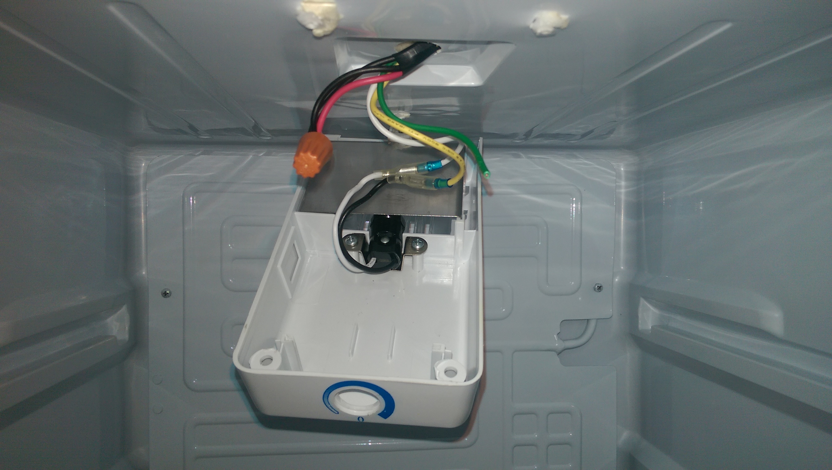
Same hole, but from the inside. Right behind the thermostat/light housing. The temperature probes and power for the heater will run in via this hole. When I am satisfied this works properly, I will seal it with silicone caulking.
gtaLnmu.jpg


Thermostat is removed from the housing and bypassed. Now the fridge will run continuously when powered. Now it relies on the Brewpi to be the thermostat.
S5UTc8U.jpg


Plug cut in half. I am using the leftover part as the overall power cable.
IMSsLYz.jpg


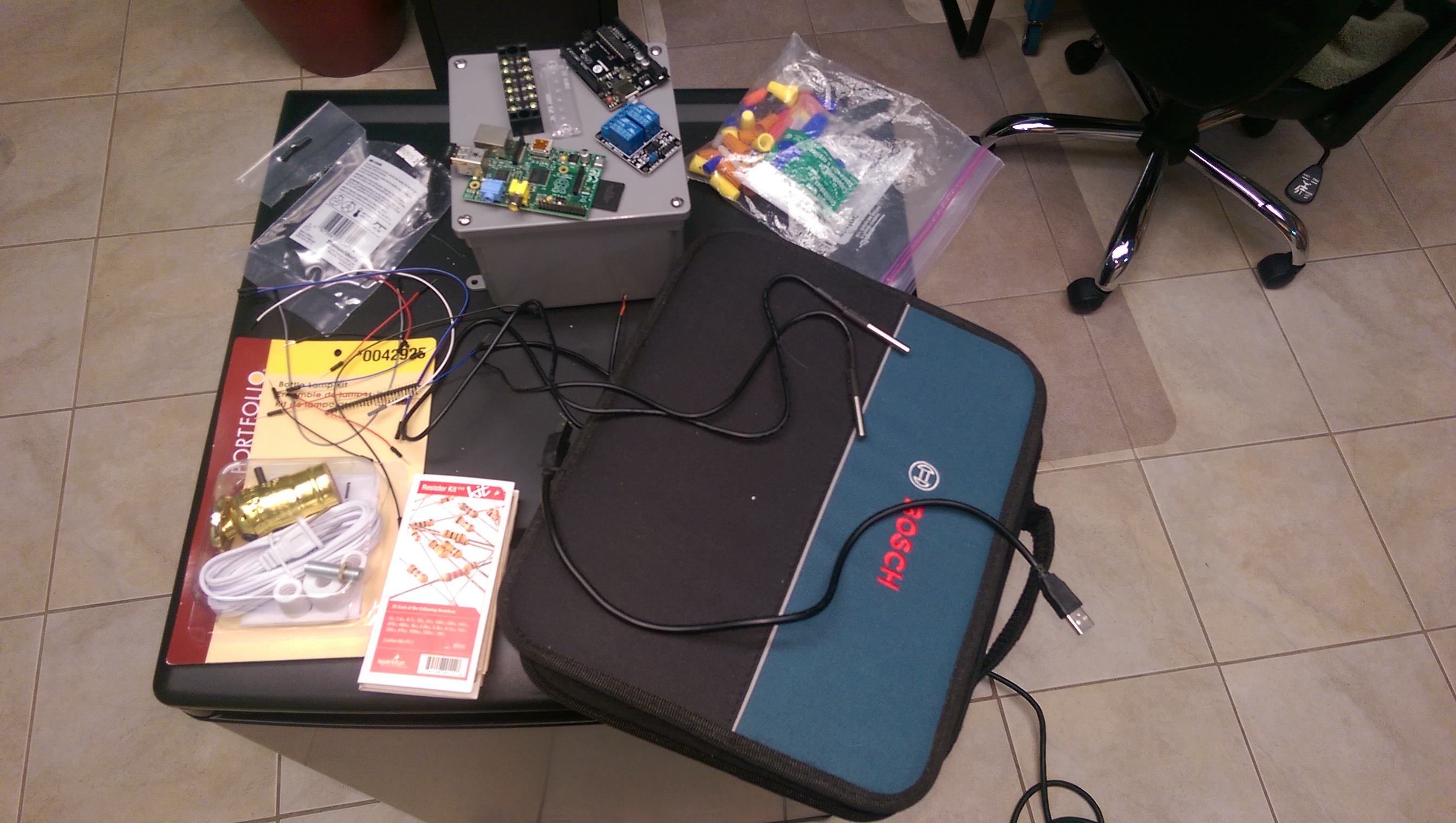
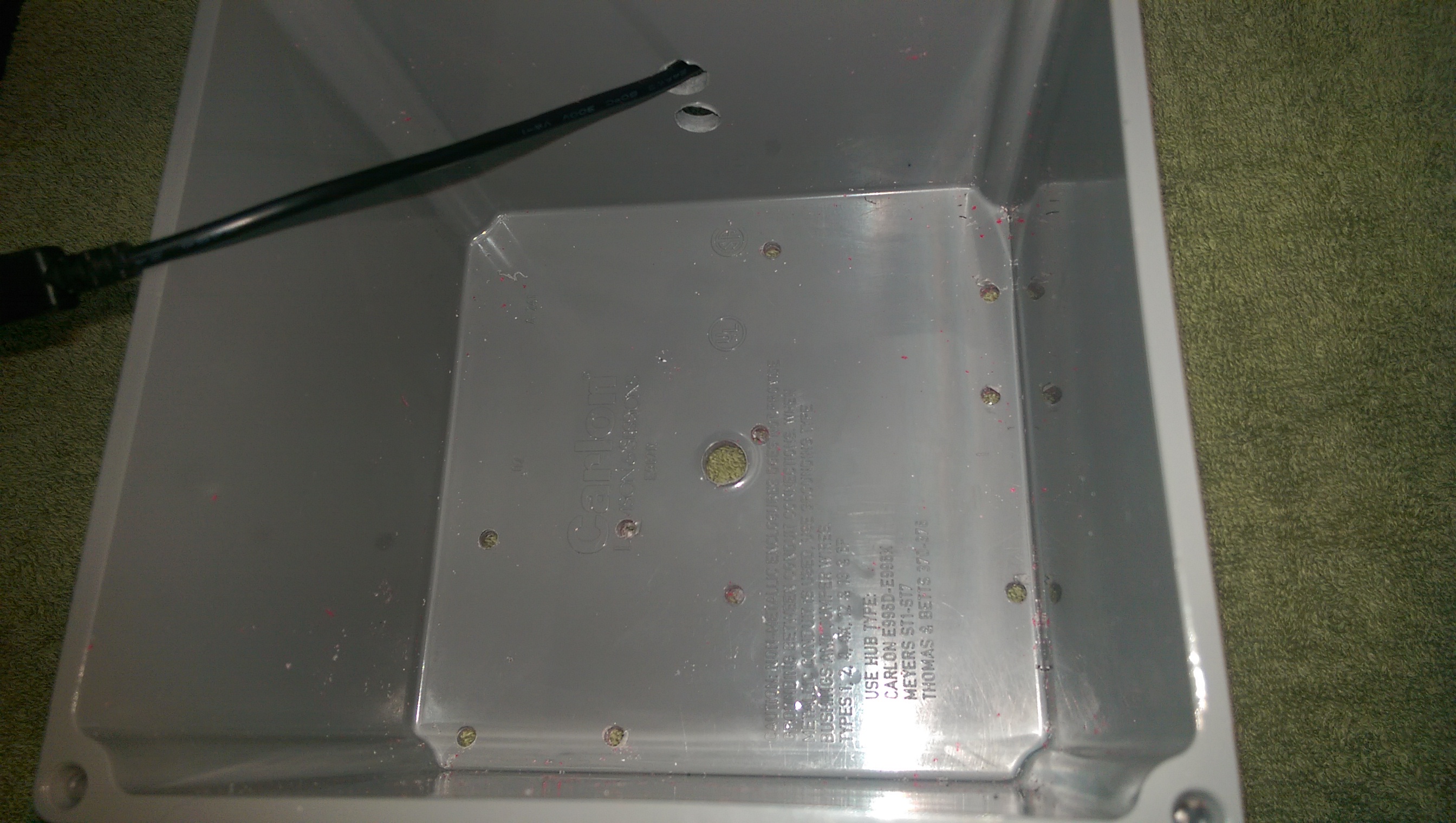
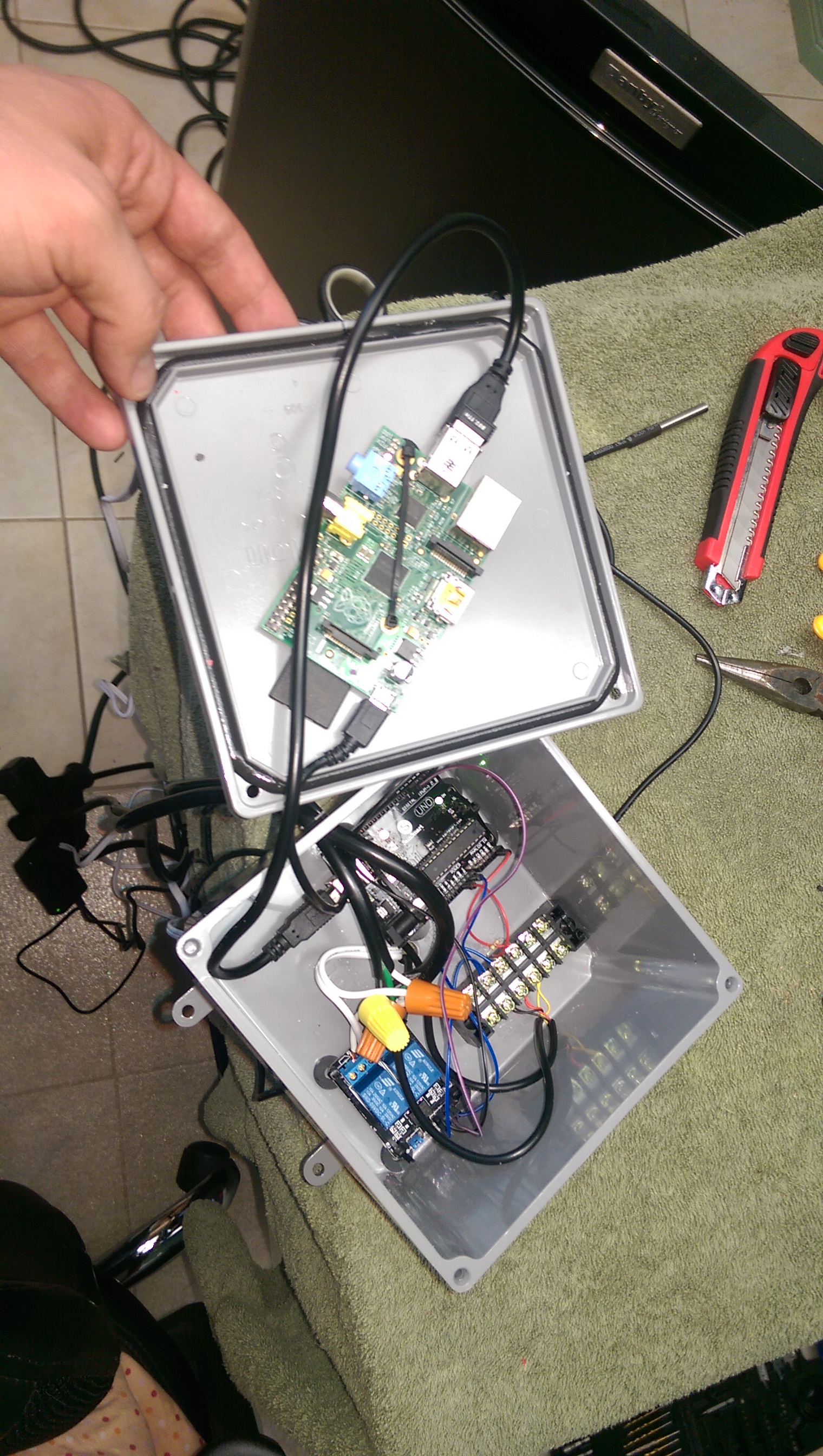
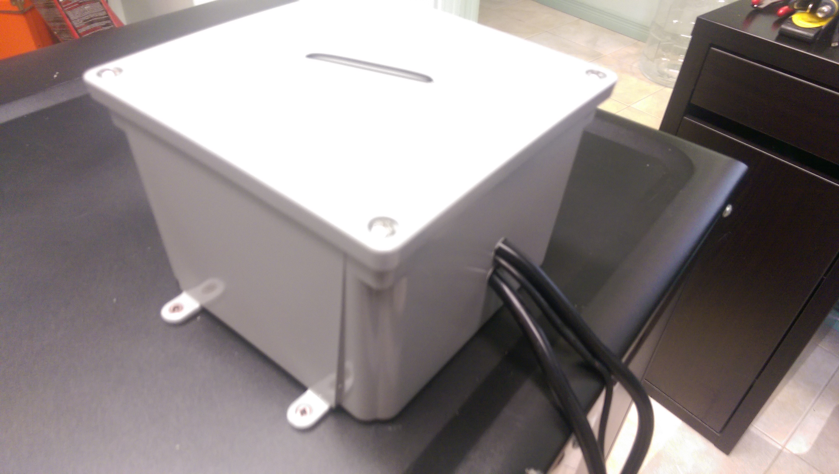
To house the Brewpi I used a junction box from Lowes. Standard 6'x6'x4' box. In this picture I have drilled the holes to mount the parts and run the cables into the fridge.
Q40sdjZ.jpg


Controller assembled in the housing. The Raspberry Pi is mounted to the inside of the lid. I held everything in place with zip ties and rubber spacers under the boards.
uPaCkYH.jpg


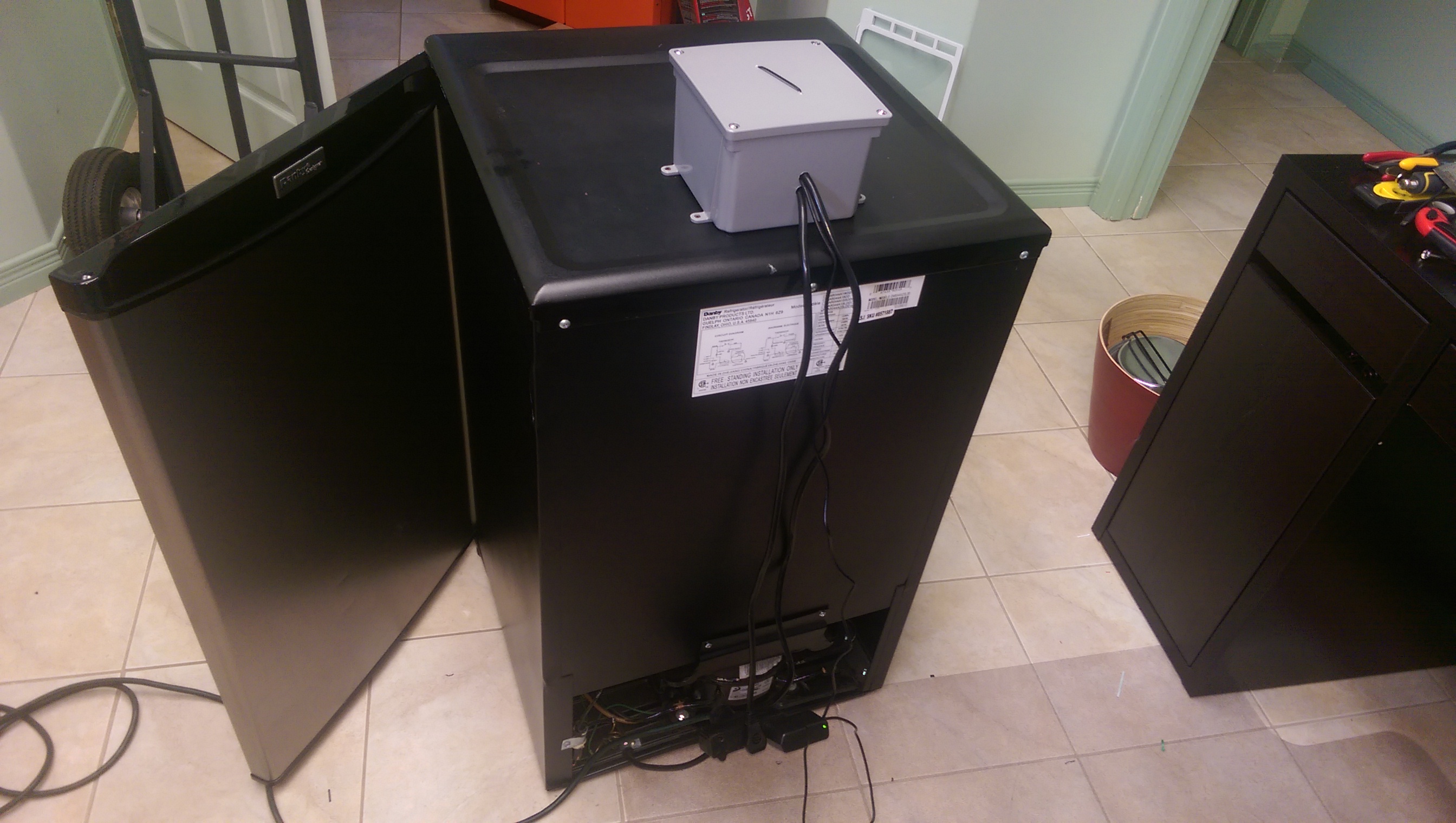
Assembled and bolted to the fridge from the back. Nice and clean.
Ymo5OEr.jpg


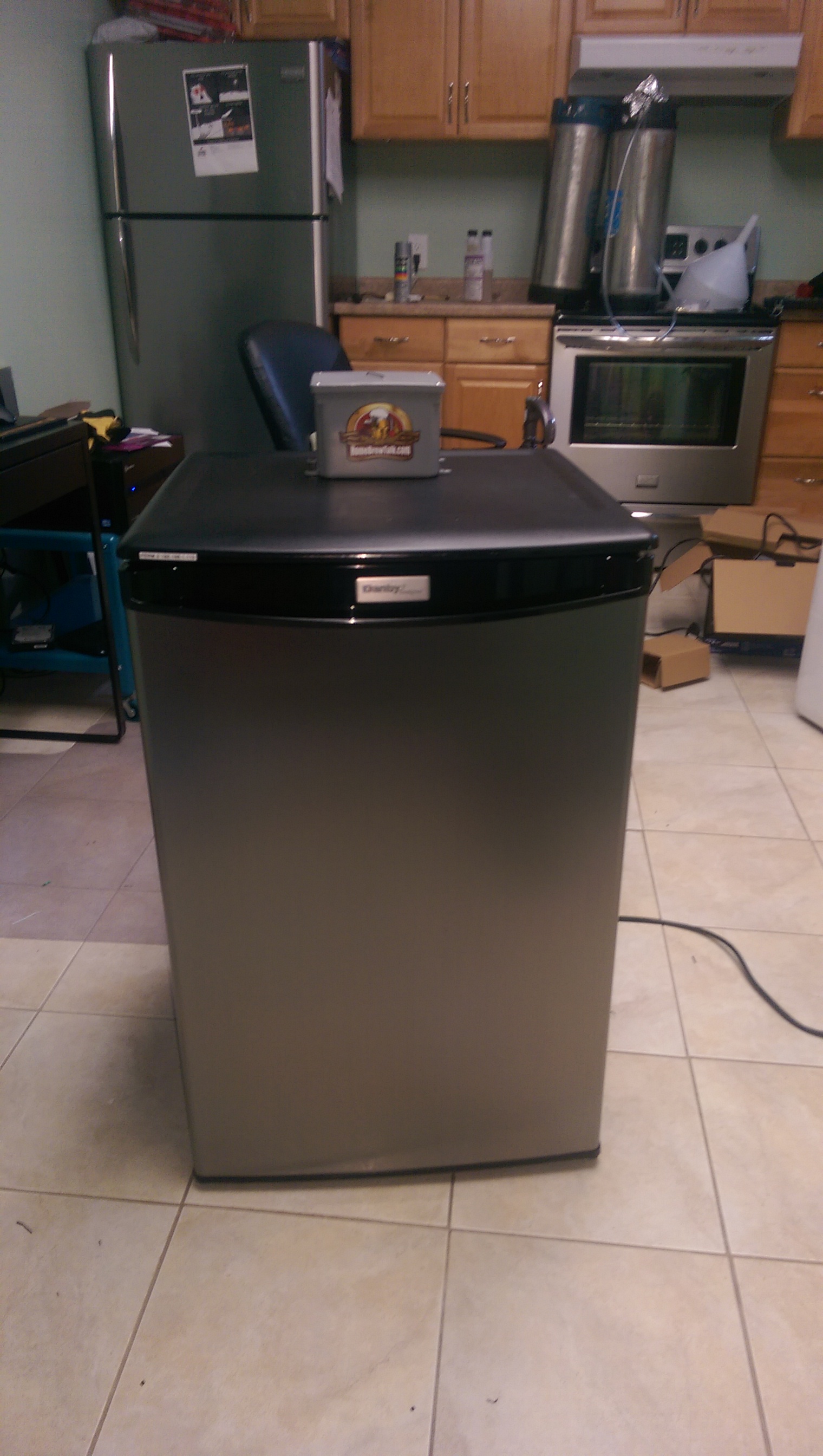
From the front. Note the HBT sticker. After much research, I am told it will make the fridge run faster!
yqlVZFA.jpg


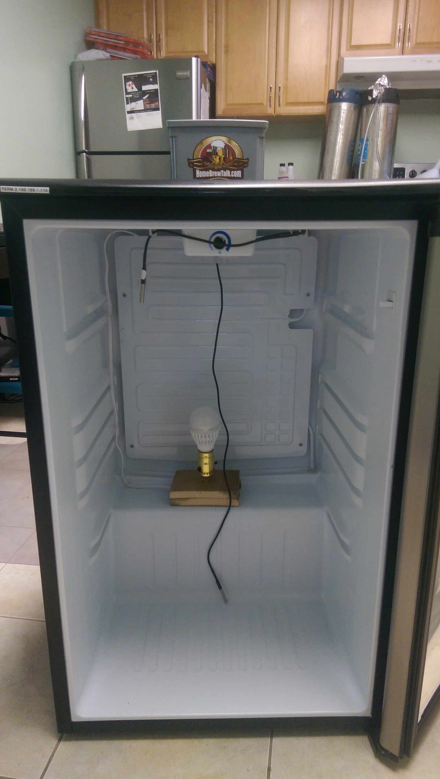
Final product on the inside.. I built the heater from some deck boards and a lamp kit that cost $6. The ceramic bulb I plan to use for it is still on order from china... LED in it to test only.
mFXDMna.jpg


ONE last shot of the control box...
aUClpta.jpg


Thanks everyone who provided guidance on this project.
 
You'll probably be fermenting in corneys with that fridge. nice build, one day I'll finally finish mine.
 
Thanks! I am pretty happy with it. Totally fits my biggest 6.5 gal fermenter (the big mouth bubbler). I may need to insulate the door on the outside though, which is fine because it lives in a closet. I am currently running tests at 50F with an electricity usage meter attached.
 
Posting this chart for a friend. He just set up his brewpi and is asking for help. He want's to know if this graph looks right.
13177209_10209906599448635_1504161774137192158_n.jpg

Is the fridge running all the time? It seems the temperature plummets when the heater turns off.
 
Anyone know why the 4-channel Sain-Smart relay boards are cheaper than the 2-channel ones? Am I missing something really simple? (other than the laws of supply and demand)

In response to what I had asked earlier about a reputable seller for non-parasitic probes, i purchased these and just tested them today and they work with Parasitic mode OFF.

http://www.amazon.com/dp/B00KUNKR3M/?tag=skimlinks_replacement-20

Just FYI for anyone looking for some on Amazon.
Do they fit in the temp wells commonly sold?
 
Last edited by a moderator:
Anyone know why the 4-channel Sain-Smart relay boards are cheaper than the 2-channel ones? Am I missing something really simple? (other than the laws of supply and demand)

I bought mine from Micro Center

where did you find a 4-channel cheaper than 2-channel?

sainsmartrelays.JPG
 
If you are willing to wait 5 or 6 weeks for shipping you can get the 2 channel relays on eBay for like a $1.50 all in.
 
Is there any other reason I might not be able to read my new sensors? I am using a basic sketch that was posted earlier. I can read my other probes in parasitic mode. I connected the first of the new sensors I received in normal config. Pin 1 grd, pin 2 data, and pin 3 5v. I fried it. So the next one I did as suggested by elkoe and connected only two leads at a time to try and find the 5v lead in case they were not the standard config. Nothing. So I contacted the supplier and asked then to send a datasheet, they sent me the maxim datasheet which of course is the one I was assuming it was. So that was no help. Is there any other reason why I would not be able to read these sensors? They say Dallas 18b20 right on the sensor. they will not read in parasitic mode at all. They fry when connected in a normal pin config manner. When I connect them with the probes I can already read, depending on which two leads I have connected, it will sometimes cause the sketch to not be able to read any of the sensors. As soon as I remove the sensor it will start reading the other. Is there any other troubleshooting I am able to do on this sensor?
 
Status
Not open for further replies.
Back
Top