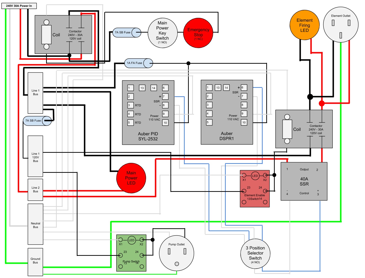
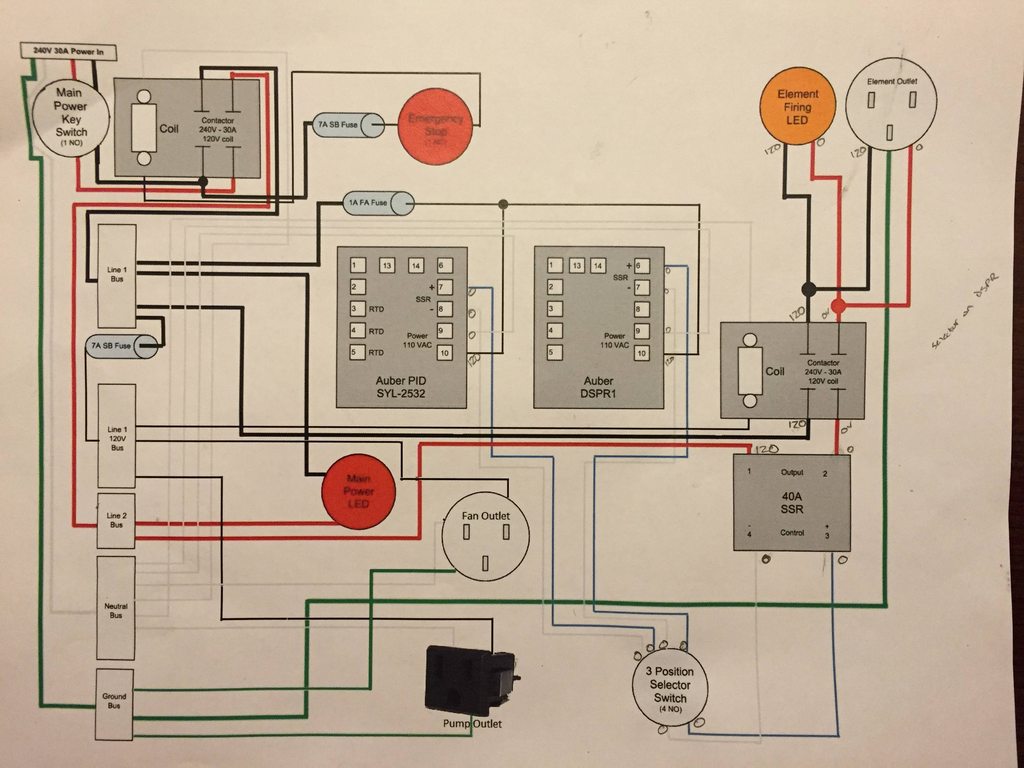
as indicated in the diagram, it is fine. the e-stop button breaks the circuit energizing the coil on the main contactor, causing the contactor to open and remove power to the entire panel. the key switch does the same thing but in an emergency, it is easier to slam down a big red button than turn a key.
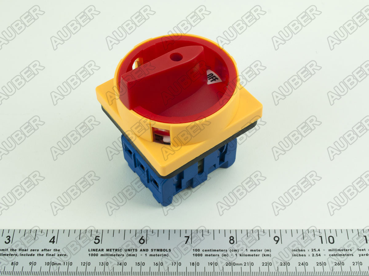
looking closer at your question, it sounds like you want to replace the keyswitch with the 32 amp switch and leave the main contactor in there? if so, the 32 amp switch would be wired in series with the main contactor, not wired in the same way the key switch would be. the e-stop would still work in this case but having a 32 amp switch and main contactor would be somewhat redundant. the main contactor is there as a means of providing complete isolation at the panel, which could be accomplished by the 32 amp switch. plus the 32 amp switch takes up a lot more physical space than the key switch. it doesn't hurt to have both but one or the other is more practical.