Automated HERMS rebuild

Homebrew Talk - Beer, Wine, Mead, & Cider Brewing Discussion Forum

Help Support Homebrew Talk - Beer, Wine, Mead, & Cider Brewing Discussion Forum:

This site may earn a commission from merchant affiliate links, including eBay, Amazon, and others.

blackheart

Well-Known Member
Joined
May 4, 2008
Messages
315
Reaction score
19
Location
Binghamton, NY
Some of you may have seen our current brew system. If not here is the thread.
https://www.homebrewtalk.com/f11/automated-herms-system-132119/

We have hit a few snags with the system after brewing several batches on it. This is not a design flaw in the overall system but rather inadequate valves. The 12v solonid valves we are currently using do not totally seal, closed or open, leaving us with partially closed valves which messes with the pressure needed to get liquids from A -> B

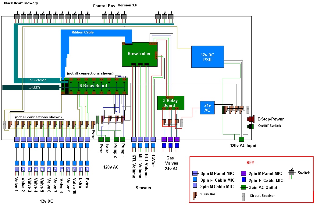
Also, we have been experimenting with building our own automated controller. While this has been fun, in the same time we have been building the brew system, Brew Troller has created more mature and reliable product. The relay board alone is worth using thanks to the addition of built in LED and manual/auto switches.

So we decided its time to rebuild, better, more automated, more modular.

Our current system is fairly modular using TC fittings and silicon tubing. This means we have almost all the parts we need to reconfigure everything with a wrench and some teflon tape. Their were a few other minor things that were bothering us.

- No dedicated water input
- No dedicated output to a fermentor
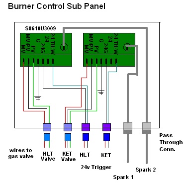
- Lots of wires hanging from the top down towards the burners

The original goal of our brew system was to make a HERMS system that used the coil for both recirculation and cooling. We havent figured out a permanent water connection to the garage/brewery for the winter so we cant rely on a plate chiller etc to cool the beer year round. This has proven difficult to design as many inputs and outputs overlap.

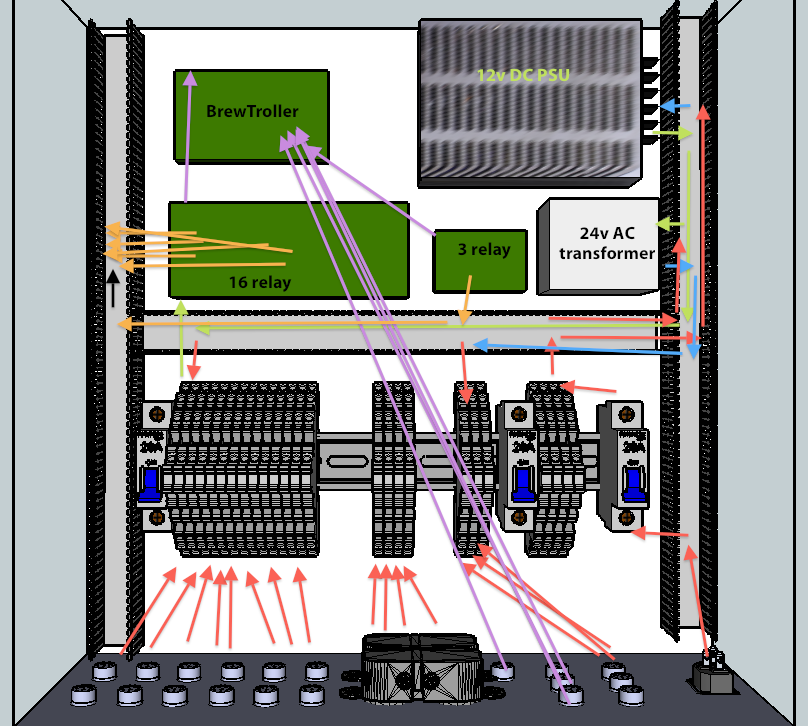
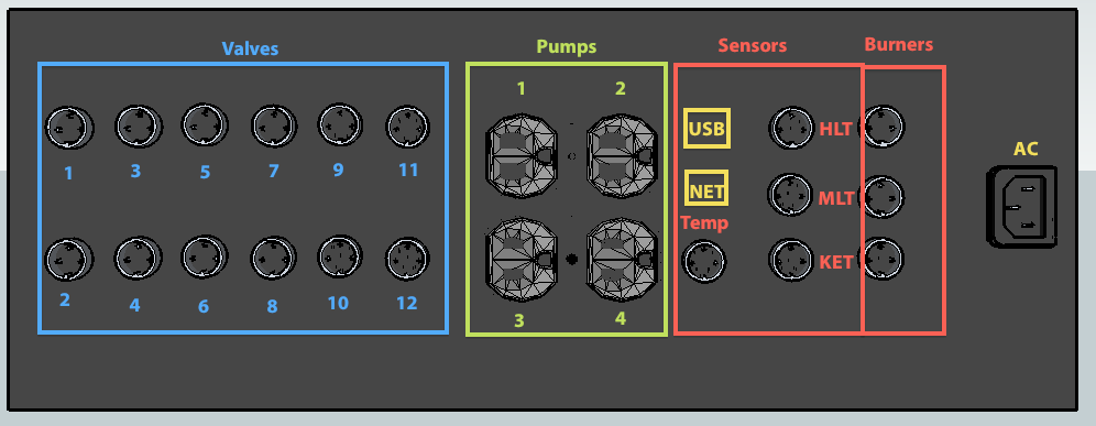
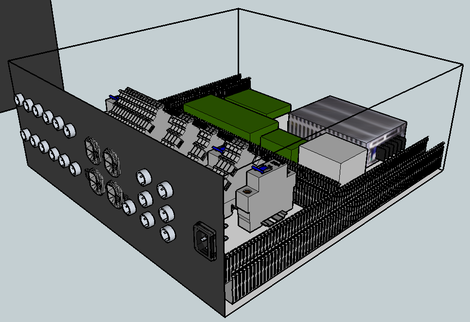
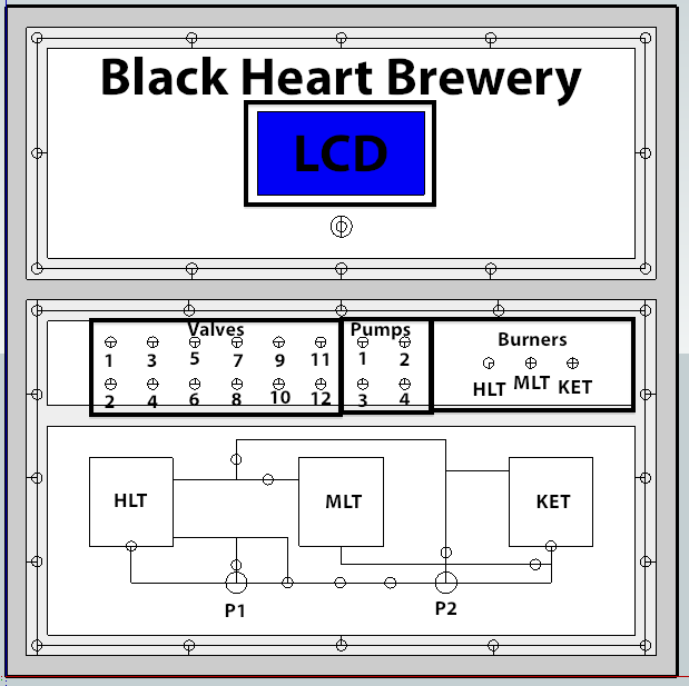
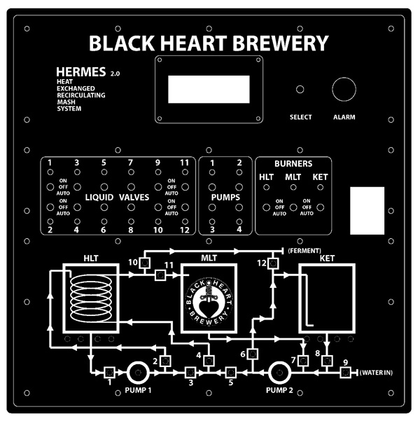
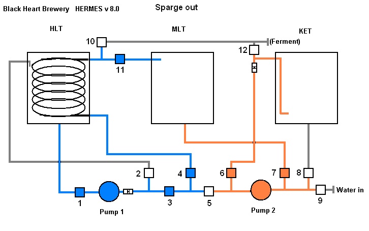
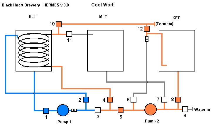
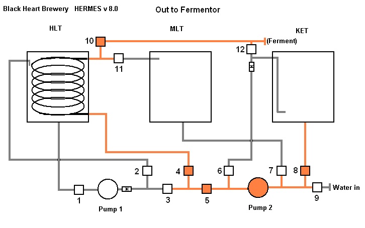
I think we have finally come up with a working design that addresses all of our current issues. We have 12x motorized ball valves, brew troller boards, and a number of other new parts to revamp the system. We are putting 9/12 of the valves under the brew system reducing the number of wires near the burners and the number of tubing runs we need.

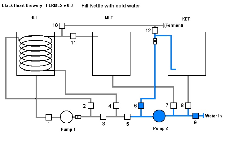
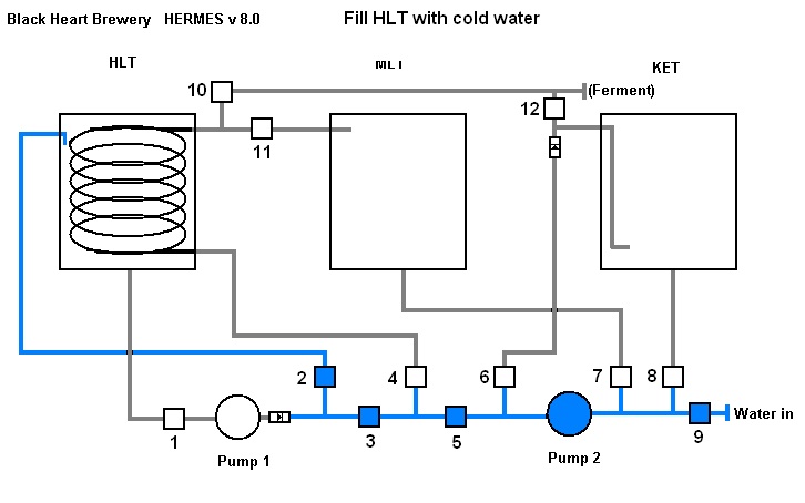
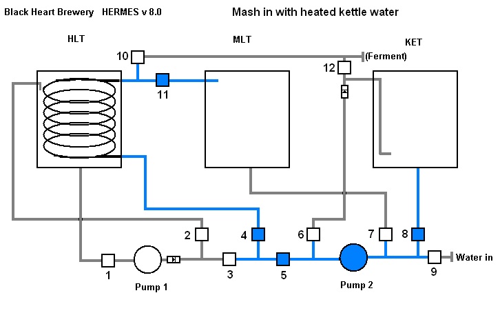
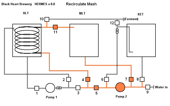
Since we are fly sparging we have designed a system that will allow HLT -> MLT -> KET transfer at the same time, and also, recirculation of the MLT or KET while the water in the HLT is recirculating to maintain its own temp.

So I present you with a short animation of the proposed system to see what thoughts others might have before we go forward and start screwing things together.
HERMES_Animated.gif

( *note one way valves on pump 1 and KET input )

flow.jpg

flow1.jpg

flow2.jpg

flow3.jpg

flow4.jpg

flow5.jpg

flow6.jpg

flow7.jpg
 
Have you found motor operated ball valves that are not cost prohibitive?.. and if so do you have a link? :)
 
Would you be interested in a plate heat exchanger design that would be a bit more flexible and easier to control with the electric ball valves. The heat exchanger would be bypassed after dough in to let the grain particles get trapped in the mash, and it would be sanitized by circulating boiling wort at end of boil. Step temperature control would be by regulating HLT water flow through heat exchanger and would be relatively immune to temperature fluctuations in HLT temperature as long as HLT was hotter than desired leaving wort temperature. After sparge was done ice could be placed in HLT for wort chill after boil to reduce water use and enable low temperature wort for lager style yeasts.
 
Would you be interested in a plate heat exchanger design that would be a bit more flexible and easier to control with the electric ball valves. The heat exchanger would be bypassed after dough in to let the grain particles get trapped in the mash, and it would be sanitized by circulating boiling wort at end of boil. Step temperature control would be by regulating HLT water flow through heat exchanger and would be relatively immune to temperature fluctuations in HLT temperature as long as HLT was hotter than desired leaving wort temperature. After sparge was done ice could be placed in HLT for wort chill after boil to reduce water use and enable low temperature wort for lager style yeasts.

Im interested.

At this point we have 10x valves, 2 pumps, tons of parts, tubing etc, and everything is reconfigurable.

We are moving forward with building the electronics as they are the same regardless of the system design and can be reprogramed easily. The only down side is if we make custom cables a specific length... which is leading me to believe it might be best to make all cables 10-15 ft (for the valves) and take up the slack later as needed, again providing a more modular design.

Wires for temp sensors and volume sensors will always remain the same length as their location will not change.

We also thought about a separate HERMS inside a soda keg but that requires a separate heat source and currently everything is 120v max and that would require some nice welding etc that we dont have access to.

Again, the constant water source seems to be limiting us to what we can do right now with regards to plate chillers etc. The design includes a water input for the warmer months when we can run a hose, but right now we will be dumping buckets of water by hand.
 
I would like to know what the electronics are programmed with and how many temperature probes you set up. I can pretty much see a LOVE controller for the two burners but is it necessary to put a temp probe in the MLT to monitor mash steps?

Other then a much of toggle switches is there already a design for a PIC controller or similar to do all the valves, turn off and on the pump and burners?
 
Everything is controlled by the brew troller relay boards. They allow both manual and automated controls. The brew troller itself controls the autmated features using an ATMega controller. Love controllers are great, and we use them for fermentation etc, but for real automated controls they are dumb.

We have two temp probes per kettle and one extra for the HERMS coil out. One is mounted in the center of each kettle and the other at the bottom for the sight glass opening. This gives a better average picture of what is happening temp wise. Temp probes are SS with 1-wire temp sensors.

Here are some pictures....

Overall wiring diagram
connections4.jpg


Box design and layout.
insidecontrol.png


Bottom connections
io.png


side view. 16x16x6"
controlside.png


We may need to make it a little larger if we are going to add in auto igniting burner valves and a controller instead of the standing pilots we are using now.
 
Forgot the front panel....
Two large cutouts in the steel covered with acrylic plates which makes it more modular and easy to make switch cutouts and a diagram of the brew system. Top would house the LCD and encoder knob to control the BrewTroller, leaving extra room for a future larger LCD. The bottom half would house both the manual/off/on switches for all the controls, as well as the diagram of the brew system with LED's for each of the valves. Flip a switch to turn on a valve and that valve lights up on the diagram.
controlfront.png
 
As requested I have taken a little time away from the .Net programming and put this revised HERMS diagram together http://picasaweb.google.com/kevin.ladue/HeatExchagerHERMSSystem#5559576427482065922. I hope it might be of some use for the folks with plate exchangers that do not want to go to the trouble of winding tubing.
The concept is you bypass the HX after dough in to let the stray grain particles get trapped in the grain bed, then circulate hot water from HLT through the HX to raise the leaving wort to next step temperature. Control of heat exchanger outlet temperature is by one electric ball valve in the HLT water circuit (V-7),you can pulse the motor open/closed in small steps to achieve temperature control.
The plate heat exchanger should allow for much easier temperature control and much faster flow and temperature rise over the SS tubing coil method. It will not be as fast as direct steam injection to circulating wort method I use, but should be a significant improvement.
 
Thanks to kladue we have ordered 2 new valves, pilots, and 2 auto igniting controllers to swap out for our current system.... Looks like we will have some parts to ebay soon.

Looks like the two controllers will go in a separate sub box near the valves. 24v on/off will still come from the main control panel as shown above. The exception is that it does not go directly to the valves but instead to the controller which then handles lighting the pilots etc.

We would love any additional comments on the overall system if anyone has any ideas/thoughts/suggestions/ridicule
 
One thing to note is that some BT users have experienced horrible interference from the autoigniting valves. There is a good discussion on BT forum that will help isolate things and prevent interference. Otherwise thongs look good to me.
 
After talking to Klaude the sub panel is really the best idea. Here is how the sub panel would connect to the main control panel, 2x 2-pin mic connectors, one for each of the two gas valves connect the two boxes.

Inside the sub box, 6x6x4", would be the two S8610U3009 controllers and thats about it. A 3 pin MIC connector connects the sub panel to each valve. Here is a drawing of what it would look like.

connect_sub.jpg


This is the box we are most likely going to use. It is weather sealed and the center where we will mount it will be cool enough for the plastic to hold.
http://www.lowes.com/pd_10030-223-E...ox&pl=1&currentURL=/pl__0__s?Ntt=junction+box

And this is a cool connector that is a pass through grommet for the spark wire which we shouldnt splice.

Connector
 
Anyone have thoughts on taking a NEMA 1 enclosure and cutting large holes in the door and bottom to mount 5mm Acrylic on it? we would most likely not cut one single hole but leave some support bracing in place so it did not flex to much.

I'm just wondering how we will attach a threaded spot to the case.... maybe end up welding nuts on the inside of the box.
 
We picked up a 16x16x6" box from e-bay and started designing the control panel. Going to start cutting it up soon. 3-5mm black acrylic that is laser etched and cut will go on top to hold all the specific components and provide some nice labels for switches etc. Here is what it should look like when done.

BOX_COLOR.jpg


Drilling, cutting and installing more components later. More pictures to follow.
 
My name is Jay, and I am a brewer over at Black Heart Brewery. Here is a video we put up online showing the new box - almost done!

 
Last edited by a moderator:
Blackheart, what valves are you using and where did you get them? I was wondering what the price on them is.
 
I was working on copying the build of you guys. I started with the brewstand. I about have that built. Family is asking for Christmas ideas for me. I was going to send them the link for these valves and tell them to just get me one of them. See how many I can get over Christmas. Wow, those valves are 79.99 a piece.
 
Thats is one sweet panel. I really like the system schematic with indicators. I will definately be stealing that idea... once I save up the $1,000,000 to drop on a crazy high tech brewery :D
 
Not sure if you purchased your gas valves yet but you may want to consider the Honeywell SmartValves for simplicity. With these valves you will not need separate ignition controllers. Your panel is already set to provide the 24VAC to the valves. The valves handle the entire ignition sequence at the presence of 24VAC. I use the intermittent hot surface ignition with standing pilots and works great. 24VAC applied to the smart valve and the hot surface igniter lights standing pilot, once the thermocouple sense the pilot the main gas valve opens and ignites the burner. Safety and simplicity. The only drawback to this compared to a standing pilot with solenoid main gas valve is it takes a few seconds for the main burner to light once the process is initiated. Nice build by the way!!!

Here is a link -

Honeywell SmartValves
 
Would it be possible to reduce the number of ball valves by using 3-way ball valves? For example 7 & 8 and 10 & 11 could be replaced w/2x3-way. Are there others? I'll need to spend some more time looking at the flow.

Great work by the way!

Chris
 
Would it be possible to reduce the number of ball valves by using 3-way ball valves? For example 7 & 8 and 10 & 11 could be replaced w/2x3-way. Are there others? I'll need to spend some more time looking at the flow.

Great work by the way!

Chris

I thake that back, 7 & 8 wouldn't work, they both need to be closed at the same time.
 
So how has the system been working out? Any tips for those of us blatantly stealing ideas from your build?
 
From your diagram, you're using 2 check valves; one at the exit from Pump 1, and another just prior to entering the Kettle.

Do you have a source for these?

I found an inexpensive ($12.99) one on Amazon (B005F7PZTO), but it has a crack pressure of 4.5 psi. Since the March 809-PL-HS pump appears to only produce a maximum of 5.23 psi (from the March website), that seems like pretty close tolerances...

Better would be one with a 0.3 psi crack pressure, but those cost more than an electrical valve!

Thoughts?
 
blackheart - A couple of comments on your brew logic... I was trying to modify your logic to fit my 3-pump system, and I ran across a couple of issues (lest I'm missing something)...

1) It appears you'll need another valve (electric or otherwise) at the end of your elevated line going to the fermenter, or else the "Cool Wort" diagram that brings wort back into the BK (e.g., whirlpool) will "leak" substantially. ;)

2) I think you'd be better off reversing the flow through your heat exchanger, delivering the wort to the top of the coils rather than to the bottom, thereby allowing the wort to "fall" through the coils, rather than trying to push the wort up through the coils against both gravity and the resistence of the coils.

3) I also think you'd be better off filling the MLT through valves 8->6->12->10->11. I know that defeats your check valve below Valve 12 (replace it with an electric valve), and it will require you to put another valve at the exit from the heat exchanger, but it will also avoid you having to run your hot strike water (e.g., 170 degrees) through your heat exchanger (likely sitting at 148-153 degrees, awaiting recirculation of the mash to start), thereby cooling your strike water down to your mash temperature before going into the MT, and then getting further cooled when it gets mixed with room-temperature malt.
 
We have made a few modifications to our system. We have removed valve 1 as it is pointless to prevent water from the HLT from hitting pump 1 as water from HLT is the only thing pump 1 pumps and it has valves 2 and 3 right after it to stop the flow. (pumps do not prevent flow while off)

If we had the option we would have done electric heating and a heat exchanger. This HERMS system was built based on the facts that we have no year round source of running water (winter time) and no floor drains. This means we need a closed system. Also, the tipping dump system for the kettles is pointless with so many wires and hoses connected everywhere. Its great that they are bolted in place and will not slide off but other than that we never ever use the tipping feature. A wet dry vac sucks out all of the spent grains and excess water when we need to clean or drain the system.

We used 2x temp sensors per vessel, we only needed one + 1 on the output.

We should have hard wired everything and used TC fittings for all valves and T's etc. This would make everything water resistant for hosing down etc and allow repositioning of valves and a more stable manifold of valves.

Sealing seems to be a huge issue. If the flow isnt good we cycle all of the valves and we reseat the TC fittings every few brews.

PBW is great and boiling it and circulating it through the system cleans everything out. It also destroys teflon tape... again, if we could afford to weld on TC fittings and use those for everything we would.

We also start boiling water in both the HLT and KTL. We use the KTL for mash in so the HLT water can be used via the HERMS coil to control mash temp and then we use that same water for sparge out. We do a combo of recirculating and batch sparging. No need to recirculate for a whole 90 minute boil but some does help.

Overall the system is working great and we have brewed many successful batches. The Kettle return line acts as a 3 way valve. It has one input and two outputs. The input enters one part of a T, one output is capped with a TC fitting and TC cap. The other output goes through a valve before entering the kettle. We recirculate the wort to chill it from the bottom of the kettle, through the coil, and back into the kettle with the kettle return valve open. When the wort is cooled enough we turn off the pump and connect a transfer hose to the sealed TC fitting on the kettle return. We then close off the valve which prevents wort from entering the kettle and instead forces it to go into the transfer hose and across the brewery into the fermentor. When done we reverse this process to empty and clean the system. We could have added another valve, or used the extra valve 1 that we removed etc to do this but its not really necessary...

We can build our system with fewer valves, shorter lines, and over all make it less complicated or less automatic. We built on a number of other existing designs from this forum and others. We also have had numerous people contact us for various questions and building clones of our work. Our design certainly isnt perfect but it works for us. our best advice would be to take what we have done and make it better and make it work for you.
 
Back
Top