Arduino controlled fermentation chamber

Homebrew Talk - Beer, Wine, Mead, & Cider Brewing Discussion Forum

Help Support Homebrew Talk - Beer, Wine, Mead, & Cider Brewing Discussion Forum:

This site may earn a commission from merchant affiliate links, including eBay, Amazon, and others.

xrattiracer

Member
Joined
Jun 4, 2012
Messages
17
Reaction score
0
Location
Seattle
Yes, my first post on homebrewtalk is about the fermentation chamber I have been building :)
I have all of 2 brews under my belt, but I dont have a place with stable temperature and I love gadgets so hence this build. Also been wanting to use an Arduino for something, and this seemed perfect.
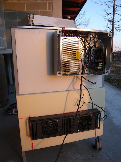
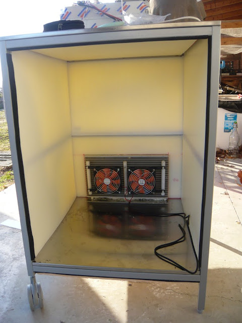
As an overview, I enclosed a stainless steel cart from Ikea with insulation and installed a peltier module. There are several reasons I went with this method.
1) Needs to be portable. My house is very small and the fermentation chamber normally lives in the spare bedroom, but needs to be able to be moved elsewhere if that room is needed.
2) Needs to be small. Kinda goes along with the above, but also necessitates the peltier module as there is not enough room for a compressor and associated plumbing.
3) Needs to be able to easily switch from heating to cooling. The climate here generally stays pretty close to fermentation temps, so there are times of the year when it will need to cool during the day and heat during the night. The peltier setup makes this easy.
4) Needs to be able to be monitored and controlled remotely. Because I can, mostly :)
Parts used, mostly sourced off ebay:
Ikea Flytta stainless steel cart.
1.5" styrofoam for insulation, with plywood walls.
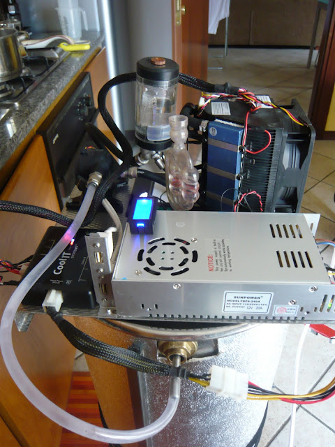
Arduino mega with ethernet shield.
400 watt peltier module.
12v @ 36 amp switching power supply.
box of misc large heatsinks.
25 amp h-bridge controller.
DS18B20 OneWire digital temperature sensors.
Ikea Dioder LED strips (hey, it needs light inside, right?).

The physical built is complete, however I am having problems cooling the hot side heatsink with the weak fans I have, so I have some much stronger ones on order. If that still doesnt work, I will water cool the external side. And until I can get that under control, I can't start experimenting with PID control.
I have plenty more pictures, but this should get it started :)

IMG_20120528_161732.jpg


IMG_20120528_150626.jpg


IMG_20120513_135720.jpg


IMG_20120604_130603.jpg
 
Curious: Why use an Arduino Mega and not a regular arduino? Just what you had on hand?

Really neat, though. I used a fridge with some bad control parts for my arduino-controlled fermentation chamber/kegerator, which was a lot simpler to implement.
 
I wanted to get a mega just to play with mostly. It will probably get swapped out with one of the smaller ones eventually.
 
Very cool. What kind of H-Bridge controller are you using? I've been meaning to do something like this for a while, but every time I go onto digikey to pick out mosfets my eyes kind of glaze over.

(I've got one of the old NuCool fridges, but I've been thinking of bypassing the controller to do both heat and cool in terms like this.)
 
Hi

I think you will need something that looks more like the blower on a forced air furnace and some ducting to get the heat off of your heat sink.

Bob
 
Well the new (extremely loud) fan has the heatsink temperature under control, but I am not terribly happy with the maximum temperature differential i am getting.

Capture3.jpg
 
hmm, i am rather unimpressed with the photo gallery here, it resizes stuff down to useless levels and wont show the original image...
the yellow line (interior temperature) is just touching the 60F line on the right.
green (exterior ambient temp) is about 73F.
red (hot side heatsink temp) is about 78F.
it made it down to 58 or so after awhile at full power, and running it at 50% power it is holding 63F.
temp rises back up pretty quickly when turning the power off so I am wondering if there isnt enough insulation. I would think that 1.5" of styrofoam would be plenty (I dont recall the exact R value).
this may turn out to be an expensive exercise in futility...

Something's not working right...I'm not sure the power on my system, but it's two peltiers and four 60mm fans for a grand total of 130W. I get about 40ºF differential without much difficulty.
 
maybe that peltier module just has horrible efficiency. i mean, everything off ebay is high quality, right? ;)
there are a few thermal interfaces that dont help with efficiency either, with the 3/4" aluminum blocks i added to make room for insulation between the heatsinks.
at 25% power it is maintaining 8 deg below ambient.

What kind of aluminum blocks are those? Mine is just a peltier with heatsinks on both sides and a fan on each of the heatsinks. The insulation is good, but it's not amazing.
 
just some 6061 flat bar stock that i cut to size and surfaced with sandpaper. used silver thermal compound between all thermal interfaces.
 
oh, you can see them in the 3rd picture in the original post. they are just to space the heatsinks apart from each other to match the wall thickness of the chamber.
 
Ah, gotcha. The problem has got to be some combination of 1) the box, 2) the heat transfer contacts and air flow, 3) the wiring, or 4) the peltiers.

Start with the easy stuff. If you turn everything off, how long will the box hold temp?

Edit: oops, you already answered that. Better insulation is key. Its probably not the walls but the joints. Also, your only seeing a 20 deg difference on the actual plates?
 
the sensor on the external heatsink is just jammed between the fins. I dont yet have one on the interior heatsink, just the ambient sensor about 6" off the bottom in the middle.
I was fairly careful with making sure there were no gaps in the insulation and used 45 degree wedges in some of the corners, but i could add more and there are some joints that i didnt tape that i still could.
 
I'm doing something very similar, I might just steal a few of your ideas. I built a chamber from scratch to accommodate my 15g conical, and I was just trying to figure out how I'm going to heat and/or cool it. I'm just north of Seattle, so I have the same weather you do. Looks like I'm going to have to learn how to use arduino and what a peltier is.
 
the sensor on the external heatsink is just jammed between the fins. I dont yet have one on the interior heatsink, just the ambient sensor about 6" off the bottom in the middle.
I was fairly careful with making sure there were no gaps in the insulation and used 45 degree wedges in some of the corners, but i could add more and there are some joints that i didnt tape that i still could.

It would be very interesting to know how much of a differential you are getting directly on the surface of the TEC. This would go a long way towards testing whether the peltiers are actually duds.

You could also do a positive pressure test on the box if you have a big fan and some duct tubing. Pump air into the box and see where it leaks out. In my experience, insulation problems on this kind of thing are more likely to be caused by air convection currents rather than direct heat conduction through the materials themselves.
 
Hi

The surfaces of the heat sinks need to be very flat where they contact the TEC. There needs to be some pressure clamping the TEC between the two surfaces (they eventually crack if there's not). You also need to be sure there's no silver thermal goop bridging the two surfaces of the TEC (Indeed it does happen). Pretty much all TEC's are the same stuff, so yours should work as well as any others.

Bob
 
I was wondering if you managed to resolve your issue with keeping the temperature low. Apparently my `cold-room` is not as cold in the summer and I need to make myself something similar in order to keep brewing...
 
I was wondering if you managed to resolve your issue with keeping the temperature low. Apparently my `cold-room` is not as cold in the summer and I need to make myself something similar in order to keep brewing...

Hi

How much cooling do you need to do? Are you 10F to hot or 50F?

Bob
 
so far I have not. I added a more powerful fan to the cold side heatsink as well, and it actually got worse. This leads credence to the before mentioned problem of air leaks, but I so far have been working on other projects and have not spent any time trying to resolve that issue. I intend to get a can of expanding foam and go crazy with it though.
 
Hi

How much cooling do you need to do? Are you 10F to hot or 50F?

Bob
Roughly about 5-10F off, so I'm assuming that peltier powered should be sufficient, but I have seen a lot of setup that aren't completed or were abandoned due to inefficiency
 
Well the new (extremely loud) fan has the heatsink temperature under control, but I am not terribly happy with the maximum temperature differential i am getting.

What visualization tool are you using for this? I really like the look.
 
Hi

A TEC is a wonderful device. Properly used they can do all sorts of neat things. There are a few things to consider though.

Like any cooling system, they pump heat. That heat winds up in a heatsink. They also use power to pump heat. It also goes into the heatsink. They are less efficient than a compressor, so the heatsink area they need will be large. They also act as a thermal "short" between the cold and hot side of the system. When they are off, heat flows "the wrong way".

TEC ratings can be a bit interesting to go through the first time. That's doubly true if they are posted on eBay :cross:. A 120W TEC likely *uses* 120W, but it does not *pump* 120W (more likely it pumps 60W). Most are rated for a 40C differential. That's at zero power pumped. At 20 or 30 C you might be using 60W to pump 20W.

20C sounds like plenty of temperature difference for just about anything you would ever need to do. Unfortunately that's the difference between the surface of the hot and cold heatsinks (surfaces of the TEC). If you are running 100W, a 0.1 C/W heatsink will heat up 10C. That's a pretty good heatsink, even with air. You just lost half of you pumping delta. The cold side isn't quite as bad since you don't have as much power there. Figure the same heatsink with lots of air only has a 4C drop. Ok, you started with 20 now you have 6. That's 6 at the heatsink surface and you still have to get the chamber to equalize with the heatsink....

Just to put some dimensions on the heatsink at 0.1C/W: With no air involved it's likely a finned block of aluminum dimensioned in feet on a side. Huricane speed air can get than down to multiple inches on a side. Water cooling blocks and large (>foot square) radiators are another alternative. You will need a high pressure pump with a pretty good flow rate though. Lots of air moved with fans either way.

In no way am I trying to say you should not do this, only to point out that there are some limits to what you can achieve.

Bob

This is all good info :)
I spent a lot of time trying to understand the math involved to figure out what would be appropriate for the application in regards to TEC power and heatsink sizes, but wasnt able to come up with any "ballpark" numbers (and didnt want to run through the rather complicated equations to come up with way too specific info).
With that in mind, the approach was just to go with what i figured would be severe overkill. And yeah the one variable that I could not find when looking for TEC modules was efficiency so I was concerned (and still am) with that as well.
I think what i have should be viable, assuming the TEC efficiency is at least reasonable.

Hi

More or less - a TEC uses >two watts to pump one watt. That's before you take all the goofy heatsink issues into account. Indeed it's more complex than that, the rate varies with the delta T. At a 40C differential you are using 120 watts to pump nothing at all. At zero degrees of delta you pump about 60 watts with 120 watts of power.

...

Of course at zero delta, you are pushing 180W into your 0.1 C/W heatsink. That heats it up by 18C. Net is that you are using 120 watts to warm the load 18C while moving 60 watts.

Crazy stuff...

Bob
 
Hi

very nice project and implementation.
I'm an Italian homebrwer and I have build more or less in the same time a termostatic fermentation chamber with peltier cells that looks like yours !

P1080508.JPG


P1080498.JPG


instead using an arduino controller I have used a ready made TEC controller from tetech with PID regulation and h-bridge power output

http://www.tetech.com/Temperature-Controllers/TC-36-25-RS232.html

here you can find the full set of picture

the full thread here
https://www.homebrewtalk.com/f51/hot-cold-fermentation-cabinet-tec-peltier-module-307438/

Now I'm moving to a different project for cooling a conical fermenter via a TEC water chiller (surplus from CPU cooler)

P1080851.JPG


full thread here
https://www.homebrewtalk.com/f51/conical-fermenter-cooler-chiller-peltier-329448/

Currently I'm using the native controller of the unit but I would like to move to an Arduino based controller

I have stared to evaluate the system and I have some doubts how to drive the H-bridge circuit via PWM.
Reading some specific forum I understood that ther is no uniform opinion on PWM frequency...someone state that the PWM frequency shoud be in a 1Khz range in order not to destroy the peltier cells.

How do you mange the PWM frequency with arduino? could you post some diagram on how to connect the arduino PWM and the H-bridge? Any code example on PID and PWM algorithm is also appreciated

sure of your support
regards
Davide
 
Hi

is there anyone that can hlep me understanding the Arduino PWM frequency issue ?

thank you and helo from Arduino native town in Itlay
regards
Davide
 
Hi

is there anyone that can hlep me understanding the Arduino PWM frequency issue ?

thank you and helo from Arduino native town in Itlay
regards
Davide

industry spec is 25hZ

Through work i had to do some PWM fan work

the webs all talked about bit banging (writing a pin on/off) thsi was sorta ok but when you tried to look for serial input the fan went 100%

then i found http://www.arduino.cc/en/Tutorial/SecretsOfArduinoPWM which explained how to use the specific PWM registers so you had a true PWM controler

following is the code i am using for another project with PWM control. I skepped PWM timer 0 as i was using that timer for something else but in the 2560 there are 4 others

Where DC stand for Duty cycle and the ## is the timer

change the dc and you change the fan speed


<Varible declaration>

int dc01; //duty cycle
int dc02;
int dc03;
int dc04;
</Varible declaration>


<Void Setup>

TCCR1B = TCCR1B & 0b11111000 | 0x01;
TCCR2B = TCCR2B & 0b11111000 | 0x01;
TCCR3B = TCCR3B & 0b11111000 | 0x01;
TCCR4B = TCCR4B & 0b11111000 | 0x01;


pinMode(12, OUTPUT); //Enable the pin that timer1 controls
pinMode(9, OUTPUT); //Enable the pin that timer2 controls
pinMode(2, OUTPUT); //Enable the pin that timer3 controls
pinMode(7, OUTPUT); //Enable the pin that timer4 controls


//this setting is for 50%+- to prevent fan runaway

OCR1B = 125; //time machine motor fan
OCR2B = 125; //Stir plate motor fan
OCR3B = 125; //cabinet fan
OCR4B = 125;


TCCR1A = _BV(COM1A1) | _BV(COM1B1) | _BV(WGM10); // init timer1 configure for fast PWM
TCCR2A = _BV(COM2A1) | _BV(COM2B1) | _BV(WGM20); // init timer2 configure for fast PWM
TCCR3A = _BV(COM3A1) | _BV(COM3B1) | _BV(WGM30); // init timer3 configure for fast PWM
TCCR4A = _BV(COM4A1) | _BV(COM4B1) | _BV(WGM40); // init timer4 configure for fast PWM

</setup>


<Void loop>


OCR1B = dc01;//time machine motor fan
OCR2B = dc02;//Stir plate motor fan
OCR3B = dc03;//cabinet fan (blow over cooling coils
OCR4B = dc04;

//change the dc## and you change the fan speed

</Loop>
 
Back
Top