E-Rig Schematic review please

Homebrew Talk - Beer, Wine, Mead, & Cider Brewing Discussion Forum

Help Support Homebrew Talk - Beer, Wine, Mead, & Cider Brewing Discussion Forum:

This site may earn a commission from merchant affiliate links, including eBay, Amazon, and others.

SweetSounds

Well-Known Member
Joined
Jan 18, 2010
Messages
1,424
Reaction score
22
Location
Des Moines, Iowa
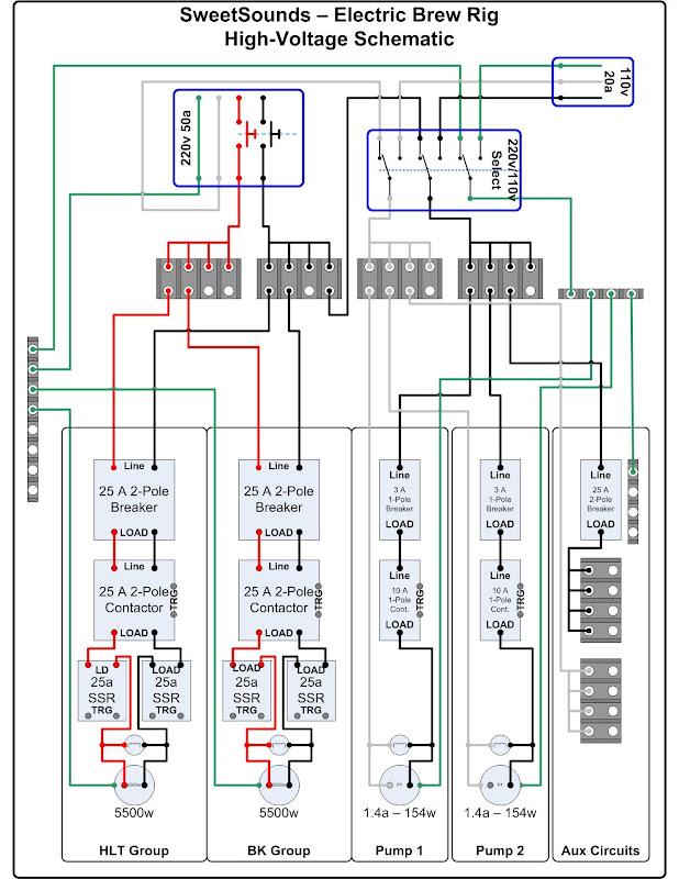
This is the high voltage schematic for my coming electric project. Peer review is the best way to find those little things that slip away when you're trying not to cross the streams, so - please have a look and see if I missed anything!

Background - It will be powered by a 4-wire 50 amp 220v GFCI protected circuit at home. But, I also want to be able to run it from any 220v circuit if I travel with it. Since a lot of the 220 I run into is no-neutral 3-wire (Range plugs, for instance) I have added a switch before the 110v equipment to break it off to another separate 110v circuit. In other words, I will be able to switch the 110v stuff from a dedicated 110v feed to the 4-wire 220 feeding the rest of the panel, when available.
SSR and contactor triggers are not in this drawing - I'm still working on the low voltage control part of the system. (The drawings are still on paper ;) )

Link to the high resolution version you can actually read:

The schematic:
E-Rig%20Electrical%20Schematic.jpg


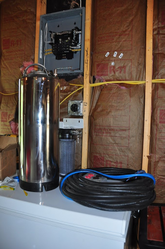
Just for fun, here's where she'll feed when it's at home! :D
DSC_9277.JPG
 
Seems pretty good. What size elements are you using?

I would hesitate using a switch and seperate 110v circuit. Actually I think I would just scrap the whole 110v being broken off of the 220v circuit all together and go with a separate 110v leg. That is how I did mine. It keeps my 240v under 30 amps.

You don't want to get into a situation where you or somebody else flips the switch and throws two live circuits together. It is just not good practice.
 
I'm not an expert and haven't really got my head around it completely yet but here are a few questions;
Why separate contactors in front of the SSRs?
I don't think I would "switch" the ground.
Not real sure about the 110/220 switching... Are you thinking of using a 3 wire 220 AND 110 feed when a 4 wire 220 is not available? Or are you just gonna limit yourself to using 110 when 4 wire is not available?
Your aux circuit says 2-pole breaker but only one line, is that a typo?
 
Seems pretty good. What size elements are you using?

I would hesitate using a switch and seperate 110v circuit. Actually I think I would just scrap the whole 110v being broken off of the 220v circuit all together and go with a separate 110v leg. That is how I did mine. It keeps my 240v under 30 amps.

You don't want to get into a situation where you or somebody else flips the switch and throws two live circuits together. It is just not good practice.

The elements are 5500 watt LWD 220v from Lowes. The straight ones that bend back on themselves.

If someone did flip the switch, it would power down the PIDs, PWM, and all of the fail-safes in the design (Which I haven't posted yet...)
The switch, for the record, will be break-before-make so connecting the 110v with 1/2 of the 220v circuit will be impossible, barring an insulation failure - (The contacts are rated not to fail before 2.5Kv).

I'm not an expert and haven't really got my head around it completely yet but here are a few questions;
Why separate contactors in front of the SSRs?

The contactors are part of the fail safe in the design. This will become more clear in the low voltage drawing. It works like this:
The normally closed relay output of the PID will trigger a relay connecting the contactor trigger circuit to the contactor, and the SSR + lead to the SSR of the appropriate element. Then, the contactor circuit passes through the panel mounted "PID - Off - PWM" switch (BK example here) through the center NC contact block. If the switch is in the "Off" position the NC contact opens, killing the contactor - and the element, regardless of any other input. There's a float switch in the contactor circuit for the HLT block as well, preventing the HLT element from firing without sufficient water present.
This mitigates several failure modes:
PID temperature alarm triggers - NC relay breaks, killing SSR signal, and contactor
Float switch triggers - Breaks contactor trigger
Switch is "Off" - Breaks contactor power
24v power supply fails (For low voltage electronics) - N.O. relay opens, kills contactors
(In 110v mode) 110v fails - 24v power supply loses power, see above :)

I don't think I would "switch" the ground.
Not real sure about the 110/220 switching... Are you thinking of using a 3 wire 220 AND 110 feed when a 4 wire 220 is not available? Or are you just gonna limit yourself to using 110 when 4 wire is not available?
Your aux circuit says 2-pole breaker but only one line, is that a typo?

That is exactly what I'm thinking. I have 50 amp 4-wire service at home, but if I take it somewhere, I'd like the option to run the elements on 3-wire 220 and the 110v devices from a separate circuit.
I am deliberately switching the ground on that part of the circuit to completely isolate the grounds of the 220v and 110v elements, when run separately. Grounds should only be joined at the panel right? I could ground everything together I suppose. I'll have to research the code on that...
I don't intend to support 110v power for the elements themselves. 220 of some form is usually available anywhere I would take this thing. I have 175' if 50 amp SJOW whip for the feed, if necessary :D

Yep - typo. The only 220 in the drawing is the elements.
That may change if I wind up working out a trade for some 220v pumps, though. In which case I would need a total of about 2 amps of 110 for the rest of the equipment. I think maybe then I'd dedicate a 110v line for that stuff and forget about switching it from a 220v hot leg and neutral.
 
I don't want to start a build thread until I start building, but here's the reasoning behind some of the complicating crap I added to the design...

All of the high voltage stuff that will switch on and off, will be switched through contactors or relays. This is because all high voltage/high current parts will be mounted in their own 16 x 14 NEMA enclosure.

That main enclosure will feed 110v to a separate 16 x 14 "Control" enclosure to power the PIDs. Then there will be a 14 pin mass connector from the control enclosure to the power enclosure. This will feed 24v DC to the control enclosure, and trigger circuits back to the power enclosure. Think of the control enclosure like a tethered remote for my brewing rig :D

This is for 2 reasons.
1) All high voltage is isolated and protected. I don't know why I like it, I just do.
2) If I decide to automate, all I have to do is wire a BCS-460 or BrewTroller to the connector, and it can run the high voltage enclosure, and therefore the whole rig.

I can control it with anything, and power it from any 220v circuit ;) I'll get working on the low voltage schematic here next week... It takes a LONG time to draw them out and make sure it's right. :drunk:
 
Seems pretty good. What size elements are you using?

I would hesitate using a switch and seperate 110v circuit. Actually I think I would just scrap the whole 110v being broken off of the 220v circuit all together and go with a separate 110v leg. That is how I did mine. It keeps my 240v under 30 amps.

You don't want to get into a situation where you or somebody else flips the switch and throws two live circuits together. It is just not good practice.

Huh???????? Looking at his diagram where do you get that? He has a switch that either selects a 110vac tap off the 220 vac line or an independant 110 vac source.
 
With 5500 watt elements, you are cutting it very close with 25 amp breakers, contactors and SSRs. To prevent nuisance breaker trips and overheated SSRs, I would step them up to 30 amp breakers and contactors and 40 amp SSRs. It really won't add much to the cost of your project.
 
I think I mis-interpreted the diagram. I read it that the square in the upper right was the switch and he would just turn it on if he needed the separate 110v source.

After looking at it a little more I understand what he wants to do. I was just a bit confused with the drawing and his overall design. It should work fine that way.
 
With 5500 watt elements, you are cutting it very close with 25 amp breakers, contactors and SSRs. To prevent nuisance breaker trips and overheated SSRs, I would step them up to 30 amp breakers and contactors and 40 amp SSRs. It really won't add much to the cost of your project.

You're right - The breakers will be 32 amp DIN rail mount, and the SSRs will be 40 Amp. Another typo...

This is exactly why I posted this thread. To catch the stuff you lose in the fog of schematicing :mug:
 
It'l work, but I'd still get rid of the 110V ckt. What's the point? If you want two boxes, power one off the other. 2 power plugs is odd.

Nice diagram. Clean and easy to read.

Thanks!

The point is, I want to use a proper GFI 220v 50a when I'm at home. At the same time, I want to be able to run the rig from a 3-wire 220v circuit if I take it somewhere. I can't peel 110v from 220v when there is no neutral. The only purpose is flexibility - if I ever need it. I don't know that it'll ever move. I don't know if I'll ever throw that switch. But, 50 amp 220v circuits are hard to find. 30 Amp 220v range and dryer plugs are almost always somewhere to be found within 175 feet of anywhere I can see myself brewing. Less then 175 feet and I'm good to go..

All of the high voltage components will be triggered by low voltage signals from the control panel for several reasons. I get to keep the HV components isolated, interlocks are easier at 24v then 120v, and I want to use a BCS or BrewTroller to run the rig - Someday...
 
Maybe it's just me, but I'm not real comfortable with 2 separate supplies in the same box. I asked a similar question when I was designing my system. In the end, I ended up just wiring for a 4-wire.

If you are interested in eliminating the questions about switching to a separate 110 circuit...
you could move all the 110 volt stuff into your "control" box and have a plug on it to connect to a receptacle in your "high voltage" box. If a 4 wire supply is not available, you just plug the "control" box into a separate outlet. Your "control" box would have 2 cords, a 110 cord and a "umbilical" cord for control lines. The umbilical would always be plugged into the HV box, the 110 cord would "usually" be plugged into the HV box.
 
That's a great idea!
The problem is right now I have other 110v stuff like pumps and the 24v power supply... So it's not just the PIDs that need the 110.

If I wind up with 220v 809 pumps, I think that would work out great...
 
The normally closed relay output of the PID will trigger a relay connecting the contactor trigger circuit to the contactor, and the SSR + lead to the SSR of the appropriate element.

Arron; I find this a bad idea as a signal loss to the PID will cause the contactor to close and energize the element. Why not reverse the design to use NO PID contacts instead with a signal required to energize the contactor?
This way any signal failure will prevent the contactor from closing.
Your way any failure will cause energizing the contactor with not having a built in failsafe system. JMO.

Yea,
I need to get on the low voltage drawings - It'll make a lot more sense then...
If we forget about all the other elements of the design and focus on the HLT contactor circuit, it might make more sense.

From the 24v supply, it goes through the N.O side of a relay, that is powered by the on/off switch. If the switch is off, or the system loses power, the relay opens killing the contactor.
Then it passes through the NC relay in the PID, so that the alarm will disconnect the contactor, killing the element.
Then it goes through the float switch, killing the contactor is the water levell is low.
The BK is similar, without the float switch.

If the PID loses power, the SSR signal will stop, killing the element.
 
You can have a electronics failure without a power failure to your system causing an element to be energized off the NC PID contact what i'm talking about.

Carl,

I am not suggesting that using two separate AC sources is optimal but the failure you describe can happen even if he is using one AC source.
 
Wayne; my thinking use the PID's NO instead of NC contacts. This way a signal going thru the PID's NO contact will not go thru the PID unless the PID calls for a closed contact. Only when the PID calls for heat will the signal voltage to the SSR be available. With going thru the PID's NC contacts and the PID not wanting heat the SSR still will be powered up, I find this a bad practice. I hear ya on the one power source to feed the brewery, multiable power sources scares me. If i'm all wet on this thread reply tell me, i'll pipe down.
 
Ok,
So I got the low voltage part of the drawing finished - Hopefully it will make a little more sense now.

I have also eliminated the 120v switch, as I think I'm getting 220v pumps - They are the last of the 110v in the old design. Now I can run off of any 220v circuit! It won't matter if it's 2 or 3 wire. Just have to watch my current draw...

If you click this link to the high res version you can download the file with the button above the picture. It's the only way I can think of to get my fellow HBT'ers the full E-Size drawing ;)

Ok, Bring the pain! :mug:

E-Rig%20Electrical%20Schematic.jpg
 
Crap, it just looks like a game of Tron to me. Of course i'm electrically challenged.


.
 
I'm confident in the high voltage side - 220 to breaker to contactor to element.

I'd like validation on the interlock design on the low voltage side - N.C. PID relay to N.O. power relay to switch to float to contactor type stuff..

I think I got it all right, but you kinda go blind after staring at a drawing like that for too long... :drunk:
 
I don't think you'll want to connect the PID and PWM "-" signals together as they flow to your SSR. You have no idea what potential, relative to ground, those two lines are at.

DC is "+" and "-", which is not necessarily the same as "hot" and "ground".

I've seen equipment in labs in college that put out a "9VDC" signal, but when measured relative to ground, the "+" was at +4.5V and the "-" was at -4.5V. And, I've seen other equipment (in that same lab) that put put out "9VDC" and the two lines measured +9 and 0. So, don't assume that the two circuits "-" lines are the same potential relative to ground.

You will want your PWM vs PID selector switch to switch both the "+" and "-" lines that go to your SSR.
 
also, your "BK PID" is still ultimately in control of the element in your BK because of the alarm wiring that controls the DPDT relay at the output of your PWM/PID selector switch. (Meaning PWM getting through to the element is dependent on whether the PID says it is allowed.)

Actually... what is the alarm for on the BK's PID? To make sure you don't go over boiling temps? :D

edit: actualy, why is there even a PID controlling the BK? Isn't your PWM all that is necessary?
 
I don't think you'll want to connect the PID and PWM "-" signals together as they flow to your SSR. You have no idea what potential, relative to ground, those two lines are at.
Good point - And they will both be switched. I drew that poorly.
The "PWM-Off-PID switch is actually 2P3T

also, your "BK PID" is still ultimately in control of the element in your BK because of the alarm wiring that controls the DPDT relay at the output of your PWM/PID selector switch. (Meaning PWM getting through to the element is dependent on whether the PID says it is allowed.)

Actually... what is the alarm for on the BK's PID? To make sure you don't go over boiling temps? :D

edit: actualy, why is there even a PID controlling the BK? Isn't your PWM all that is necessary?
Another good point :D
The PID is there because I'll be heating my strike water in the BK. I want to be able to hit a specific temp and hold it there.
In "Boil mode" it'll just boil, and I doubt the alarm will ever be set under 215 or so. It also allows me to play with "Brutus" like setups, less the HERMs in the BK.
But it's mostly there so that if the power dies to the control panel, the elements die with it.

There are a few more components that I still want to add too... A few more RTD sensors for mash temp, HERMs output, and chiller output, and a main volt meter, and Ammeters on the main and both elements. I just haven't found suitable devices yet ;)
 
Good point - And they will both be switched. I drew that poorly.
The "PWM-Off-PID switch is actually 2P3T

Do you mean 3P3T?


Walker said:
<why is there even a PID>
Another good point :D
The PID is there because I'll be heating my strike water in the BK. I want to be able to hit a specific temp and hold it there.
In "Boil mode" it'll just boil, and I doubt the alarm will ever be set under 215 or so. It also allows me to play with "Brutus" like setups, less the HERMs in the BK.
But it's mostly there so that if the power dies to the control panel, the elements die with it.

Ok. If you have a PID on your BK, then do you need the PWM? A PID that sports a manual mode will perform the function of a PWM, and you won't need the selector or a separate PWM circuit. Less is more.

My system has a PID and PWM with a selector switch to control the BK, but that's because I will likely add a dedicated electric HLT and/or tinker with a RIMS tube in the future. If I do one of those two things, my selector switch will be abandoned and the PWM will be dedicated to the BK while the PID becomes dedicated to a HEX.
 
Do you mean 3P3T?


Ok. If you have a PID on your BK, then do you need the PWM? A PID that sports a manual mode will perform the function of a PWM, and you won't need the selector or a separate PWM circuit. Less is more.

My system has a PID and PWM with a selector switch to control the BK, but that's because I will likely add a dedicated electric HLT and/or tinker with a RIMS tube in the future. If I do one of those two things, my selector switch will be abandoned and the PWM will be dedicated to the BK while the PID becomes dedicated to a HEX.

Wait - It'll need to be 4p3t? I gotta think about that one

You're probably right. But I'm also not sure what my process will intimately be. I've been bouncing back and forth between RIMS and HERMs and maybe a Brutus-like setup. I want it to be flexible enough that all I have to do is re-label the panel if I want to change things up.
Hell, I'm getting close to just ordering 3 more PIDs for the rest of the temp sensors. They are cheap enough, and have alarm relays. it's tough to find panel mount RTD displays with an alarm for less than the little $30 Auber PID.
 
Wait - It'll need to be 4p3t? I gotta think about that one

Why 4 poles?

Your diagram has a 2P3T switch. One pole of that switch is passing through 24VDC to the lamp and BK contactor when the switch is in either of the ON positions, and the other pole is passing through either the PWM or the PID "+" signal.

You just need 3P3T so that you can also switch the PWM or PID "-" signal as well as the 24VDC and "+" signals.

Yep - You're right.
I'll get the drawing fixed.

E-Rig%20Electrical%20Schematic.jpg
 
The "24VAC" relays you are using... is that the trigger votage being referred to, or the max load voltage allowed through it?
 
Wait - It'll need to be 4p3t? I gotta think about that one

You're probably right. But I'm also not sure what my process will intimately be. I've been bouncing back and forth between RIMS and HERMs and maybe a Brutus-like setup. I want it to be flexible enough that all I have to do is re-label the panel if I want to change things up.
Hell, I'm getting close to just ordering 3 more PIDs for the rest of the temp sensors. They are cheap enough, and have alarm relays. it's tough to find panel mount RTD displays with an alarm for less than the little $30 Auber PID.

LOL... This sounds so familiar. Mark my words... you're gonna end up with a BCS-460 or Brewtroller (go ahead, ask how I know ;) )
 
LOL... This sounds so familiar. Mark my words... you're gonna end up with a BCS-460 or Brewtroller (go ahead, ask how I know ;) )

That, sir, is EXACTLY why I'm building the low voltage control panel separate! Well, that and I'm getting 8 16 x 14 x 8 panels... Might as well use 2 :D

Essentially, everything that switches on or off is remotely triggered with a 24v AC signal or SSR feed from a PID. I'll just have to fashion the BCS or BrewTroller a harness that will connect to the high voltage panel to run the relays and contactors.
 
That, sir, is EXACTLY why I'm building the low voltage control panel separate!

BTW, I like the idea of the controls being on a tethered panel with the burly part of system separate.

That thought rolled through my head after I was all done building and realized that I could have bought two smaller enclosures and mounted the 240V stuff in a box under the stand and then just had a small box with a couple of switches and control circuits in it mounted where I could easily reach it.

I am NOT going to rebuild things, but I think the idea is a good one.
 
Yep!
Sure is.

I switched to 24v AC mid-design because I can't find 24v DC contactors, and I can find 24v AC relays.

I'll get that changed too :tank:

Cool. One last thing... :D


Those relays are double-throw, but that's not really necessary. Normally open single throw would work. Don't know if it makes a difference in price or if you want the double throw to give you flexibility for some other thing you might want to add later.
 
BTW, I like the idea of the controls being on a tethered panel with the burly part of system separate.

That thought rolled through my head after I was all done building and realized that I could have bought two smaller enclosures and mounted the 240V stuff in a box under the stand and then just had a small box with a couple of switches and control circuits in it mounted where I could easily reach it.

I am NOT going to rebuild things, but I think the idea is a good one.

Thanks!
I don't want to have to rebuild mine either, which is why I'm trying to cover all the bases in the first shot.

I know the process is going to change - Because I don't have a process yet. My first run with this rig will be my first all grain beer. Months of lurking and asking questions has so far proven to be just enough to get me in trouble (Just ask SWMBO ;) )

I'll make a note on the relay - Good catch.
 

Latest posts

Back
Top