A 3-Vessel 2-Tier 1-Pump E-RIMS for 30A

Homebrew Talk - Beer, Wine, Mead, & Cider Brewing Discussion Forum

Help Support Homebrew Talk - Beer, Wine, Mead, & Cider Brewing Discussion Forum:

This site may earn a commission from merchant affiliate links, including eBay, Amazon, and others.
I'm having a hard time seeing the point, as well, especially after your explanation.

Maybe a fuse between the PID and the SSR, in case the SSR ever shorts? In that case, would the 5A catch the short in the SSR before any damage to the PID? Can SSRs even short?
 
I'm having a hard time seeing the point, as well, especially after your explanation.

Maybe a fuse between the PID and the SSR, in case the SSR ever shorts? In that case, would the 5A catch the short in the SSR before any damage to the PID? Can SSRs even short?

The output of an SSR can short within itself, meaning that it is constantly on. However, the input is isolated from the output using an optical link (LED and photo transistor) so there is no worry about the input shorting to the output other than by a wiring mistake. It is impossible to protect against all wiring mistakes, fuse or no fuse. If you really want a fuse then it should be on the power input to the PID, and I am not going to fault such a setup.
 
As you are pointing out, the 24VAC system is floating with respect to ground. I thought about it (connecting it to 120V Neutral) but I think there are only drawbacks with that connection, safety for one. In some systems it will be connected to earth ground via a large resistor to reduce electronics interference, yet preventing large ground currents. Do you think it is necessary? I am not sure.

Well, I'm not an electrician, but here is my opinion. I would connect the 24V system neutral directly to the chassis ground. With this arrangement, ground faults will trip the primary breaker. I think this would be desirable since your HLT float switch will be sitting in water and is a potential point of failure. I work at an electric utility and have seen pressure switches go to ground from moisture getting in through bad gaskets.
 
Well, I'm not an electrician, but here is my opinion. I would connect the 24V system neutral directly to the chassis ground. With this arrangement, ground faults will trip the primary breaker. I think this would be desirable since your HLT float switch will be sitting in water and is a potential point of failure. I work at an electric utility and have seen pressure switches go to ground from moisture getting in through bad gaskets.

You have a good point there. I will connect it and check it out. Thanks.
 
Well, I'm not an electrician, but here is my opinion. I would connect the 24V system neutral directly to the chassis ground. With this arrangement, ground faults will trip the primary breaker. I think this would be desirable since your HLT float switch will be sitting in water and is a potential point of failure. I work at an electric utility and have seen pressure switches go to ground from moisture getting in through bad gaskets.

Sdugre, I have been thinking about your suggestion. As you mentioned it I knew I had read about this before here on HBT. But when I think about how a ground fault in the float switch can trip the GFCI I realize that I don't understand how this will work. I made a very simplified circuit diagram of the whole system, showing only parts essential to this issue.

FloatGroundFault.jpg

On the left we have the main panel followed by the sub panel where the GFCI is located. The GFCI measures the currents in L1, L2, and N to make sure that they balance. If there is an imbalance it means that some current is "escaping" though ground somewhere and the GFCI will trip.

The control panel has a 24V transformer, a switch, and a relay. The 24VAC neutral is connected to earth ground as you suggested.

The HLT has a float switch that can close the loop with the transformer, activating the relay. The HLT has a heater element whose cable is providing ground for the HLT.

A ground fault in the float switch is shown as a resistor and a dashed line. The orange loop shows how the ground fault current will circulate through the transformer. Zero current is flowing towards earth ground, which means that the GFCI will not trip.

What am I overlooking here? Did you mean that it will trip the over-current protection? (Transformer has 2A CB.) Is there another way that a float switch ground fault can trip the GFCI? Anybody please share any insight you may have.
 
You are correct. A fault beyond a transformer will not trip the GFI. My thinking was it would trip your 2A breaker.

However, I just had a conversation with two electricians at work on this issue, and they said that it's not necessary to ground the neutral of control transformers under 50 volts and 50 VA. In fact, swimming pool lighting circuits are usually 12 VAC and ungrounded. Bottom line is I don't know what I'm talking about, so I apologize for the confusion.

No worries, it was interesting to look into this anyway. It is too bad that it didn't work because it'd be useful if it did.

Something went wrong with the circuit diagram. I just swapped the PNG file for a JPG and it seems to work again.

Thanks for the updated information any way.
 
Today I soldered a 1" s.s. lock nut to the BK for the heater element. For a more detailed description with pics, see my sig. "How I soldered...".

BKInside.JPG


I put the center of the heater four inches above the bottom. My idea is that the heater is not going to interfere significantly with the whirlpool as the trube cone is forming. This remains to be seen in actual practice though. Stay tuned for results in the next few weeks.

In the upper right you can see a whirl pool fitting and a 4" Pt100 temperature sensor peeking through a sight glass 'T' from brewhardware.com.

I am almost ready for a test brew. Just some plumbing needed for the counter flow chiller and the water filter. I do not have the brew stand ready, not even close (I don't even have the material), but I can jury-rig the main parts for a test brew, perhaps next week. I am so exited I can hardly wait!
 
Did you ever find a replacement for this? This looks like it would work, but is a bit pricey.

Great job on the rig, BTW

OK, so now I need to replace those DPDT relays. I tested the panel some more with all elements connected. The relays worked OK for a while, but then two of them gave up their ghosts. As it turns out it was not their inadequate current rating (30A on NO, but only 3A! on NC) that did them in, it was my after-the-fact "fix". I only need SPDT relays, but these had two poles; DPDT. I decided to parallel the two poles to mitigate the low NC rating. That was a mistake. In theory it is fine, but in reality it failed.

In retrospect I see what happened. The NC contacts are connected to neutral while the NO contacts are connected to a hot. The common terminals are connected together and to one side of the heater. One pole may switch just a hair quicker than the other. During the short time that one pole is still connected to neutral, the other pole makes contact with the hot, and we have a dead short in the relay. This does not seem to happen when the heaters are not connected, so the slight contact arcing when making and breaking currents must play a role in this.

I ordered three open Potter & Brumfield 25A SPDT relays for $12 each from Ebay. Hopefully I can install them in time before the weekend and do the inaugural brew (11 gallon Rye PA). New recipe, new ingredient, new brewery, what can go wrong? :D
 
Good luck with the first brew.

Did you test out the system with water? Just curious how well the RIMS works at two different power levels.
 
Good luck with the first brew.

Did you test out the system with water? Just curious how well the RIMS works at two different power levels.

I did not spend enough time at high power to be able to tell. The relay soon welded itself stuck in low power mode. I tried to heat 6 or 7 gallons of water with the RIMS on low (750W), but it took too much time. It held temperature well on low though. The plan is to use high power to step up the temperature, and switch to low power to maintain temperature.

The Little Giant pump worked really well with a strong flow once it primed. It was a pain to prime, though. Any air in the input hose made priming real slow. I need to find a way to deal with this. Maybe I can bleed the output into a can, somewhere below the input liquid level. I experimented a little but it got messy real quick.
 
Do you plan on tuning the PID on high or low? I would think low would be best for maintaining a constant temp, but maybe you'd overshoot when ramping up to a higher temp on high?
 
Quaffer-
Awesome build and great ideas, thank you!

I have read over this multiple times and I think this is a good solution for what I want to accomplish.

My goal is to go all-grain electric with keggle HLT , Keggle boil and a cooler mash tun.
For now I won’t have a herms/rims.

I had assumed I’d have to run two 240 lines to power each 5500 w element. BUT it would seem that I can get by on one 240 run and a 120 (to run pump).

I really like the idea of a single 240 line and maybe a 120 if need be. This way I can relocate/move whatever and not have to worry about access to two 240 lines.

What I cannot decipher for the life of me is how you take 240 to 120 on demand.

Thanks again,
Loptr :mug:

You have to be sure to run a 4-wire cable to the control panel. You will need both hot lines, neutral, and ground. 240V is achieved by connecting both hot lines to the load. 120V is achieved to connect one hot (either one) and neutral to the load.

I think your question is how I switch a heater between 240V and 120V. If you can read schematics, this here PDF will show how it is done.

I will try to explain. For each of the heaters I have one beefy contactor that can break all connections to the heater and the following relay. There is an SPDT relay that switches one side of the heater element between neutral (low power) and the other hot (high power).

I have now installed properly rated SPDT relay for low/high power switching. With my current setup, there is still occasionally a problem switching from high power to low power. On high power there is a strong current that does not like to be interrupted. If we are unlucky and switch the relay at a point in the cycle where the current is at its peak, then an electric arc is draw across the contacts of the relay. After repeatedly switching high-low-high-low for a while I hit the point where a strong arc occurred and the circuit breaker triggered.

My interim solution is to only switch from high to low when the PID output is off, which means that there is no current going to the heater. I just wait a little until the PID switches off then I switch to low power. Alternatively I can set the PID to manual and 0% output.

I am going to experiment by rewiring one power switch. Currently from left to right I have Off, Low Power, High Power. I will try to move the off position to the middle, like this: Low Power, Off, High Power. If this eliminates the arcing then I will rewire all the switches that way. It is pretty simple; I swap one contact block from NC to NO, and then add a NO block to the other side. No changes to the wiring harness needed, just one local wire at the switch.
 
On request I have uploaded the Sketchup model to Google's 3D Warehouse. I had to split the model in two because it was too large for a single upload. The control panel is a separate model that can be imported into the brewery model.

There should be several components useful for sharing, both in the brewery and the control panel. Click on the pictures to go to the 3D Warehouse.

 
Did you ever post a parts list with sources and prices? sku numbers are helpful as well.
Just finding appropriate hardware given all that is out there is a challenge.
Even knowing the source, say Mouser, you can spend hours looking for something appropriate.

Thanks - Greg M.
 
Did you ever post a parts list with sources and prices? sku numbers are helpful as well.
Just finding appropriate hardware given all that is out there is a challenge.
Even knowing the source, say Mouser, you can spend hours looking for something appropriate.

Thanks - Greg M.

I have not posted a parts list. I will try to give you some of the parts numbers.

Terminal block end stop: Mouser part No. 845-CA802
Terminal block endplate: Mouser 845-EP2.5/4UN
Terminal ground block: Mouser 845-CGT4U
Terminal block: Mouser 845-CTS4U-N
Altech 2A circuit breaker: Mouser 845-1CU2R
Altech 3A circuit breaker: Mouser 845-1CU3R
Altech 15A 2-pole circuit breaker: Mouser 845-2BU15R
Altech 5A circuit breaker: Mouser 845-1BU5R
Mean Well +5V, +15V, -15V power supply: Mouser 709-PT45C
Tamura 50A Hall effect current sensor: Mouser 838-L03S050D15
24x12 VAC 50/60 Hz control transformer, 75VA: Automation Direct PH75PG

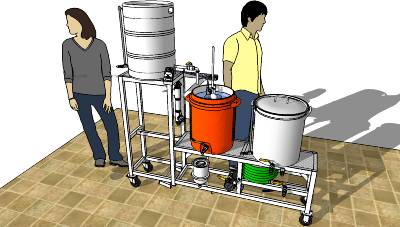
If you open the Components window in Sketchup you will be able to glean some information from the component properties. For example:
Siemens 42CF35AJ 3-pole contactor, 50A resistive

The switches and lamps on the front panel were from whoever had a good price on Ebay, often direct from China. In my experience it is less risky to buy directly from the Chinese than from some shady two-man operation here in the US. I have always received what I ordered from China, but not always so from domestic sellers.

PIDs, SSRs and their heat sinks (40A, 25A) are from Auber Instruments. Note that Auber recommends far larger heat sinks than the ones included with some SSRs on Ebay. If you are going to mount the heat sinks inside the panel like I did, then I suggest you use Auber's recommendations. For forced air or external heat sinks you may get away with the smaller ones.

Most the other electrical parts came from Ebay or some obscure place on the web, can't remember all of it. If you have a specific parts number request I will try to look it up for you.
 
Thanks for the part numbers and sources -
Acouple of mine, alternatives to Auber
I use giorgio11185 on eBay for SSR's and heatsinks:
$14 for a 25amp 480v ssr with heatsink, free shipping
for Auber's 40 amp contactor/relay, pioneerbreaker.com has them for half the price, with
reasonable shipping. Auber's shipping is fast but very expensive.
 
You have done such excellent work, man.

How's it going on this build? Have you brewed on it yet?

I have TIG welded the locknuts onto my HLT and BK. I would like to know/see how you wired up the element(s). Did you use a conduit box?
 
You have done such excellent work, man.

How's it going on this build? Have you brewed on it yet?

I have TIG welded the locknuts onto my HLT and BK. I would like to know/see how you wired up the element(s). Did you use a conduit box?

Thanks, Earthbound. I have brewed ten times on the system even though it is not finished yet. I got a MIG welder before the holidays, and I have almost finished the brew stand now. A few more details then paint. I will post an update.

I have not finished the connections to the heater elements. I just jury rigged some protection around the connections so I would not bump into them. Not ideal. I am leaning towards gluing PVC fittings on the elements, but make it so that I can open them up in the back and tighten the terminals. If that does not work then conduit box. It will take some experimentation I think.
 
Subscribed. Can't wait to see the finished product and don't forget to take picture of every angles including elements in MLT
 

Latest posts

Back
Top