I'd really like to talk with you on your progress. I think you are going to have an awesome system.... I'm anxious to get back to this project, so I will be giving P-J another call soon and taking more pictures as I go.
Thanks for the update.

I'd really like to talk with you on your progress. I think you are going to have an awesome system.... I'm anxious to get back to this project, so I will be giving P-J another call soon and taking more pictures as I go.
Isle Royale? You're forgiven.")

I'd really like to talk with you on your progress. I think you are going to have an awesome system.
Thanks for the update.
 Not used to takin more from the table than I bring.
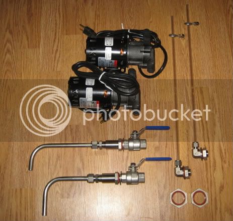
Holy Cow, this is EXACTLY what I need!
Only difference is I will run a 2000w RIMS in my MT. I assume thats not difficult to add?
What an awesome thread. Thanks for sharing your time and knowlage guys.
I'm a firm believer in the 'Pay it forward' theme. But, I'm workin from a pretty big deficit on here.


The PIDs use temperature sensors that are places in the kettles. The sensors can be mounted differently depending on your choices. In the systems that I've built, I use thermal wells.Ok, how does the PID get the actual temp reading. Am I missing something?
The PID temp probe info is illustrated on the PID diagram:My 'RIMS in a toolbox' is set up that way, but I did not see it in the schematic in this thread.
Or did I overlook something? Electronics is not my strong suit.

Awesome! I'm really interested in your build and how things turn out for you. As you know, I'm in your corner cheering you on.My enclosure is ready to be milled for the hole layout now! ...
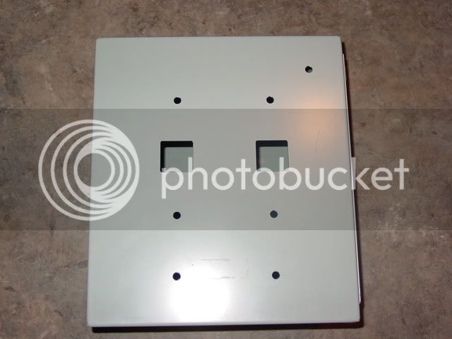
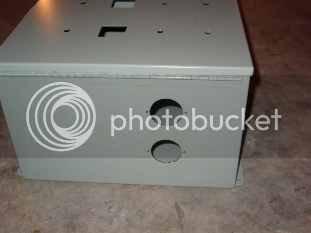
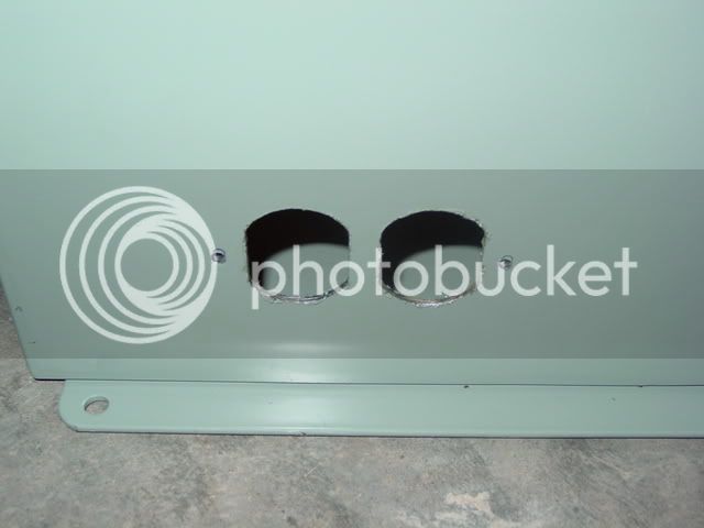
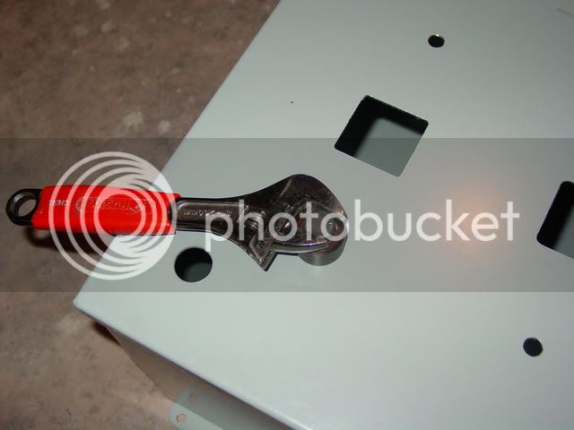
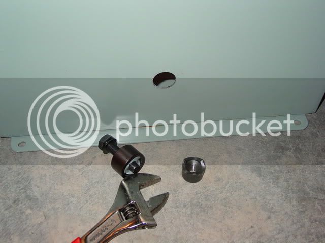
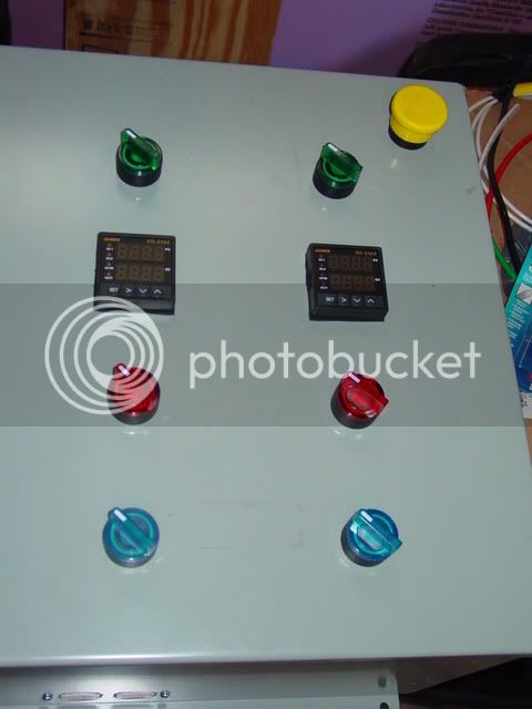
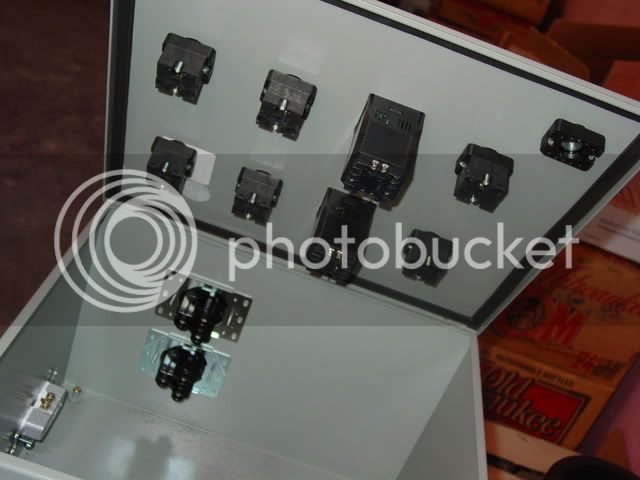
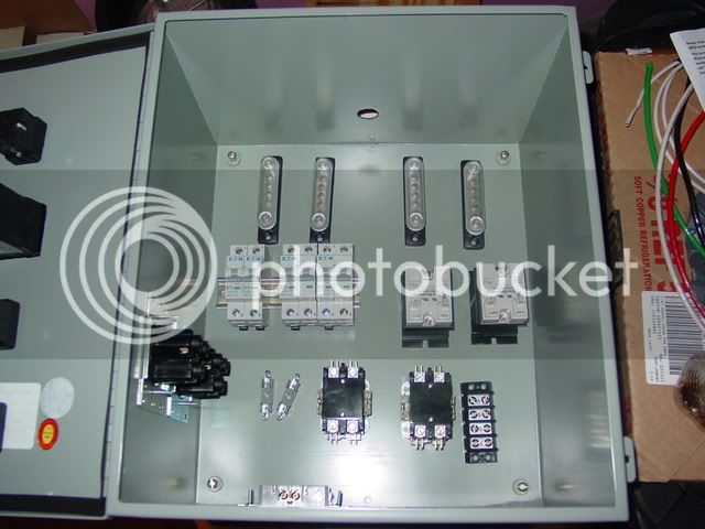
We milled out my enclosure today!
I didn't take any pictures of the process, but we had fun doing it. Took about 4 hours with plenty of BS-ing and taking our time.
I'll take some pictures of the milled box and post 'em up when I get a chance.
TB
This link will take you to an excellent wire gage chart: cerrowire.com
If you intend to use crimp on connectors, solder the crimped connection after crimping. This is important on the high current lines (heating element connections for example). Trust me on this one, it will save you a lot of grief down the road.
I don't mean to come across in a negative way, but you throw out a bit of info and then say don't ask.I've done some marine wiring and you can do either soldering or crimping but NEVER combine them. I thought is was a great combination as all marine wiring comes tinned, but in fact it will make the connection weaker. Don't ask me for the details at this moment but if have seen the guidelines from the connectors years ago.
Walker (if you're still here), how did you run your TC or RTD wires through your enclosure? Do you have any pictures of that?
Thanks,
TB

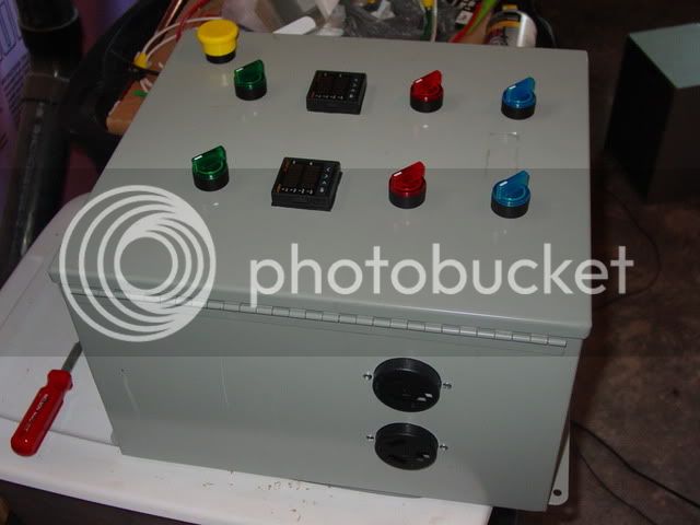
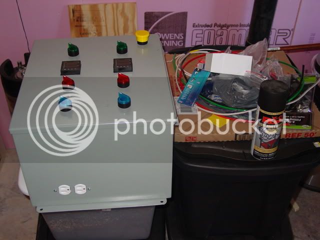
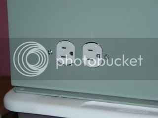
i have the exact same box as you. pretty much identical. i just got mine all wired up and water tested last night for leaks. what i did was install those omega panel mounts from auber. i used tc's instead of rtd's tho. I mounted the omega's right above the 240 outlets.
i mean i was testing the box to make sure everything works. i was water testing the pots to check for leaks. i built the same thing that you are building.
http://yfrog.com/3d0821001437aj
http://yfrog.com/n90821001437j
http://yfrog.com/my0821001438j
http://yfrog.com/6z0821001435aj
http://yfrog.com/mr0821001435j
http://yfrog.com/j00821001434aj
http://yfrog.com/9d0821001434j
sorry for the links. didn't have another way to get them to you without email.
rian
Enter your email address to join:
