OP
OP
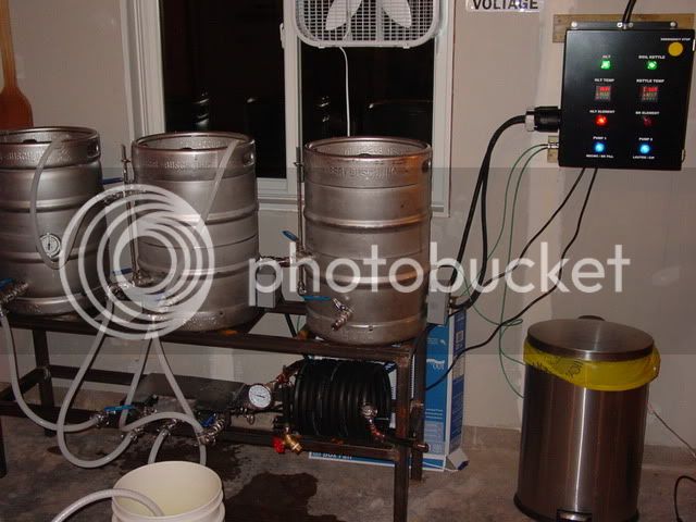
No issues yet. I have not done back to back brew sessions, nor do I plan to. I have stuck my hand in the box after a brew day (unplugged of course!) and it was warm, but not hot. I would think that with the size of the enclosure and the heat sinks, there isn't much risk of overheating.Hey man I hope all is well....working on my build more now and was wondering if you have had any issues with heat in your box? I am planning on mounting my SSR's and heat sinks similar to yours.
With a CNC end mill!I was also curious on how you cut the holes for your PID's and 110 outlets for the pumps? Thanks in advance.
I realize that isn't a tool that everybody has access to, so you might want to ask what others have done. Or, you could find a machinist who appreciates good homebrew and ask a favor.
Good luck with your build!


 ).
).