Not to hijack, but when are we gonna see that new rig, Jon?
Soon.... Maybe I'll put some teasers in my old build thread.

Not to hijack, but when are we gonna see that new rig, Jon?
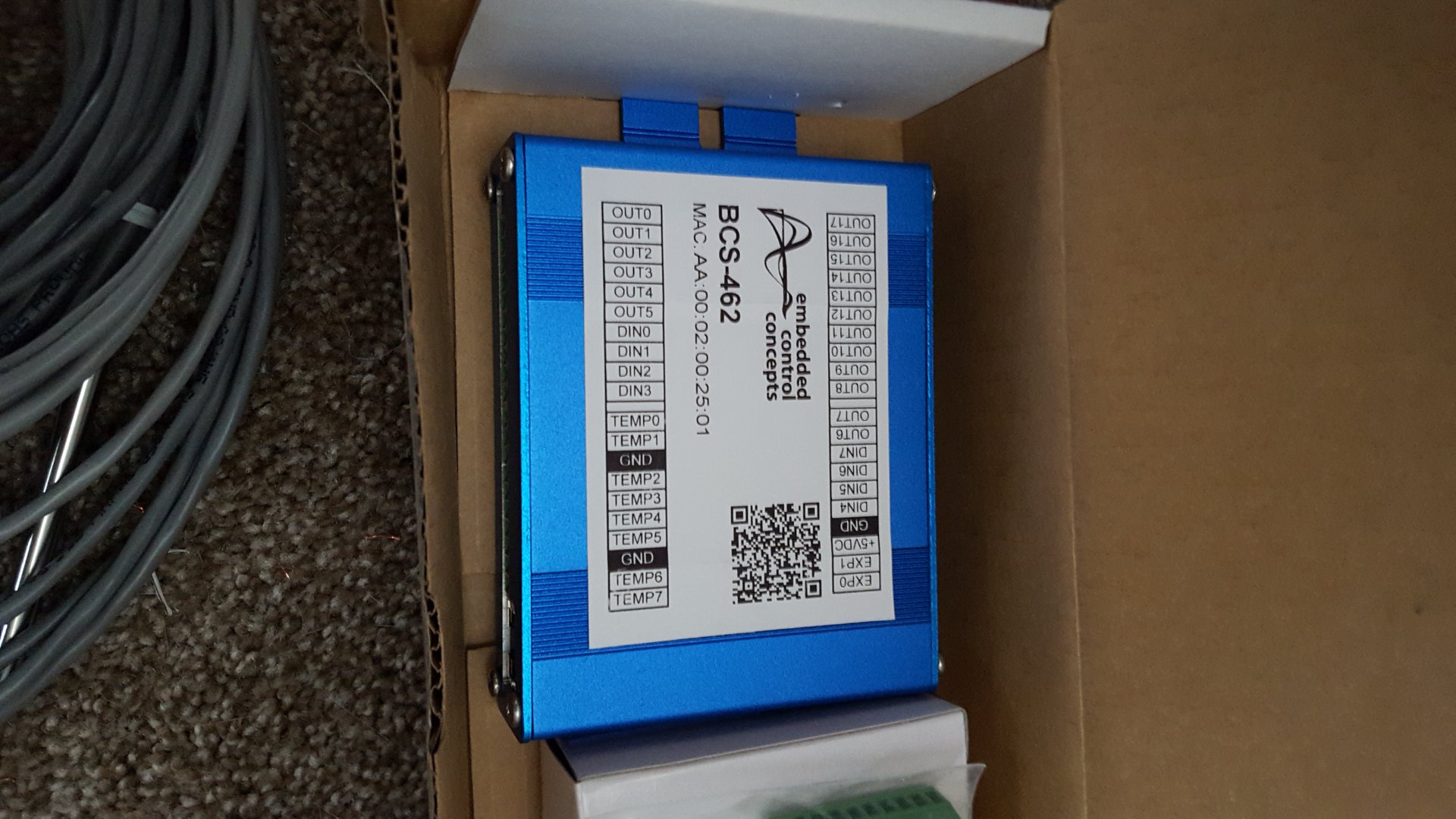
so slight issue. Pretty sure the relay I purchased isnt working with the BCS. I did however manage to get the BCS up and running via wifi, go me and me semi IT skills. I assume the output on the BCS is too low to trigger the relay. I went ahead and dropped the coin for a DIN mount one that is recommended by ECC so we will see.
What are the specs on your relay? Are you trying to "trigger" the relay with 5V or "power" the relay with 5v? The relay coil uses more power than the BCS outputs provide. The outputs are only used to "trigger" the relay and the relay must have it's own power. The outputs of the BCS are limited to 20ma each. If you overdrive them, you run the risk of burning out the output driver circuit.
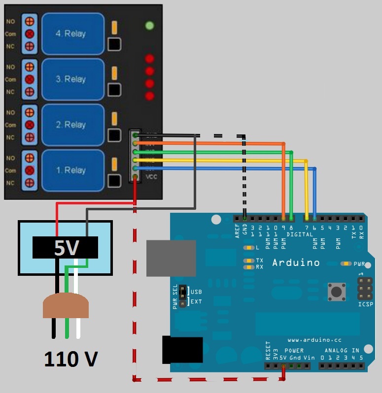
One thing that can also stop a board from working properly is by not having the grounds tied together. Do you have a jumper going from your 12V negative terminal to the BCS negative terminal? All grounds must be tied together.
I didn't try this. Would this basically be adding the wire for the dashed black line in the picture I linked above?
Yes. For low voltage control systems to work together, they must all use a common ground.
This may or may not solve your issue though. Depends on whether or not the board is triggered by an active high.
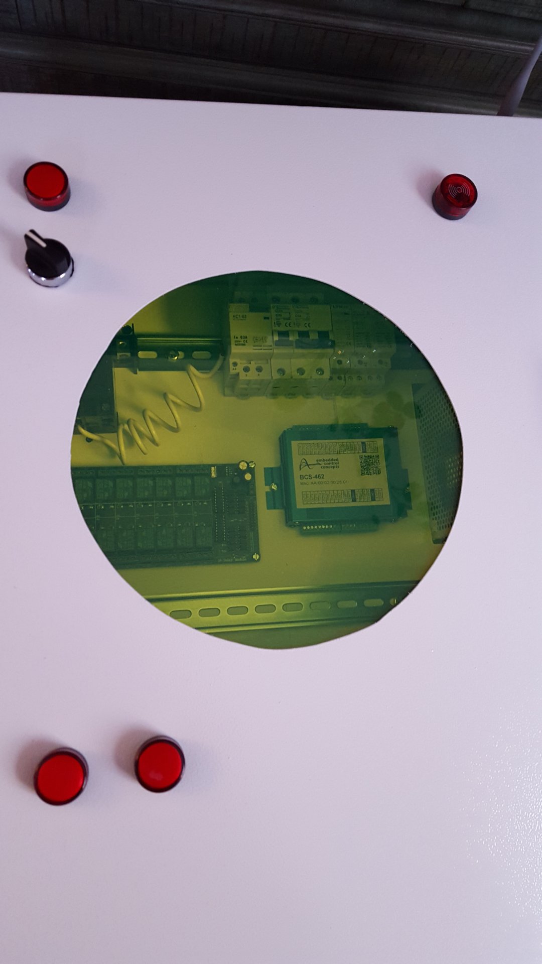
But your board in post 127 above will definitely not work while the one in 128 will.
The first board (blue one) could actually be modified to work, but it would take a bit of soldering. It's the opto-couplers that require the inverted signal, so you could just bypass them. You can remove all 16 opto-couplers and place a jumper over two of the pins. You can then run the BCS 5V trigger voltage right into the ULN2803 darlington drivers on the board (18 pin chips).
Best solution though - use the Electronics-Salon boards.
Let us know how that crimp tool works!
What sensor is in the probes?
I think there are two mistakes you can make that will lead to certain wifely doom...
1. Let that hot glue gun dribble on the carpet
2. Trim stranded wires and leave all those little copper needles in the carpet fibers just waiting to attack her delicate toes.
Oh gotcha. Make sure you compare with an accurate thermometer like a thermapen. You want to make sure temperature is conducted properly from fluid to thermowell to probe to thermistor.
Enter your email address to join: