Got a pic of the inside? Trying to figure out how you got the 'in' and 'out' on the same side of that little box. Since the pump has them in a 'L' configuration.
Here you go...
I opted to not mount the pump via the bracket for two reasons:
1) I needed to rotate it at an angle to get the outlet aimed correctly
2) The threaded inlet collar is beefier than the plastic mounting base anyway
Because the clearance of the outlet didn't allow the CPVC elbow to fit, I used my heat gun to form the connecting piece. This allowed me to mount the QD's directly to the threaded portions of the pump and the CPVC connector to act as bulkhead fittings thru the project box wall using some large OD washers to firm things up as that's where there will be pressure on the box to insert/release the QD's etc...
The connecting piece of CPVC appears more collapsed at the angle in the pic than it does in person. In any case, the inner diameter of the pump outlet is actually smaller than the ID of the CPVC, so there's no real restriction. I tested the pump flow after it was all plumbed together, and it was nowdifferent that when running solo.
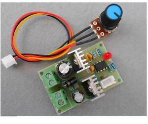
The pump PWM controller, on/off switch, and speed adjust pot all mount directly on the lid. The power connector is epoxied in the lower left corner.
Hope this helps


")