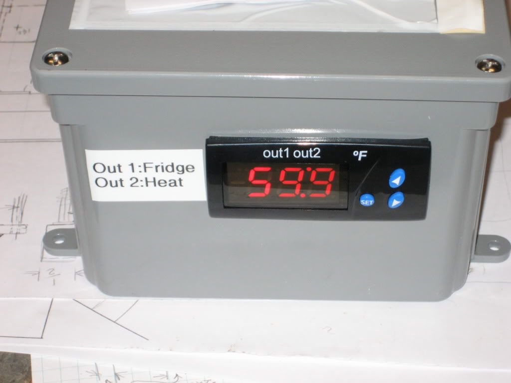
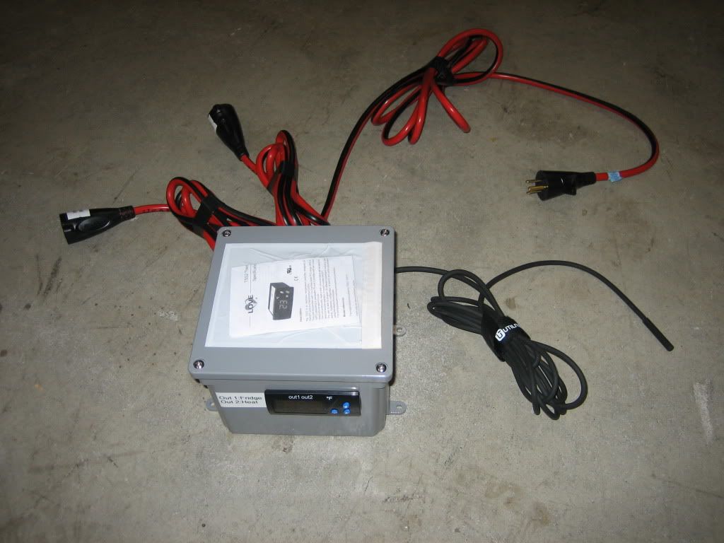
Here is what I did using a Love TSS2 with a TS-61 temperature probe. I bought two extension cords to provide the wire and plugs & receptacles. I left about 6ft of cord attached to the female receptacles into which I plug my fridge and heater (40w heating pad). The male end of the extension cord I left about 10' long so I could easily plug it in and then slide the fridge back in place. According to the wiring diagram I have the fridge running off the higher capacity set of contacts and the heater off the lower capacity contacts.
I contained this inside a PVC plastic enclosure which is why the enclosure is not grounded. All the outlets in my brew area are GFCI protected providing an added layer of protection.
Keep in mind that all wiring (except for the temp probe) must carry the full current load of your fridge & heater. I used 14ga wire. You can use house wiring wire nuts or Lowes & Home Depot sell small insulated junction strips that allow you to tie up to four wires together. They are in the aisle next to the electrical tools & supplies (wire strippers, wire nuts).
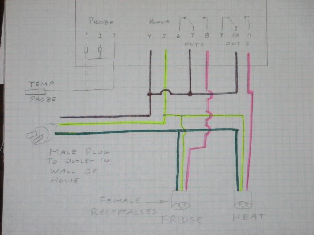
Connect the two wires from the temperature probe to terminals 1 and 3. It does not matter which wire goes where. Shown as pencil lines on drawing.
From the male (prongs sticking out) plug of the extension cord cut off the outter layer of insulation exposing the three wires inside, and do the same with your two female receptacles.
Connect the three green wires together so you can pass the ground connection on to your heater and fridge. There is no ground connection to the Love controller. Shown as green on drawing.
Connect all the white wires from your two female receptacles and male plug and run a jumper up to terminal 5 on the Love controller. This is your common and serves as a ground. Shown as yellow on drawing.
Now, take the black (hot) wire from your male plug and connect it to terminals 4, 7 and 10 on the Love controller. This is getting always "on" power to the controller (terminal 4) and to your two output relays (terminals 7, 10).
Connect the black wire from a female receptacle to terminal 8 and label the receptacle "fridge". Output 1 (terminals 6, 7, 8) is the output that can handle up to 16amps.
Connect the black wire from your other female receptacle to terminal 11 and label the receptacle "heat". Output 2 (terminals 9, 10, 11) is the output that can handle up to 8 amps.