
azwillnj
Well-Known Member
TLDR: This is going to be a huge post, If you are just interested in the photo gallery and some short descriptions click this sentence.
I would like to start by saying thank you to everyone on this forum, the wealth of knowledge on here is incredible, I couldnt have done it without you guys.
I started my brewing journey last Christmas when my girlfriend got me the Midwest beginners kit in the Irish Stout variety.. It was all uphill from there (downhill financially lol). After brewing about 8 extract batches I decided to step it up a bit, and being an engineer I am unable to half-ass anything and so starts my build.
I made an immersion wort chiller out of copper for my extract batches and because of that after much research and reading about everything I decided to go with an E-HERMS system using my chiller as the heat exchanger coil.
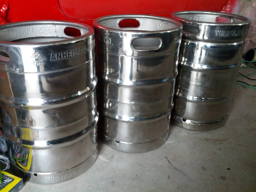
I managed to get three kegs from the local distributer for the deposit and spent over 50 hours polishing all three of them. It was a terrible experience but I guess in the end they look nice and it was sorta kinda worth it.. maybe?
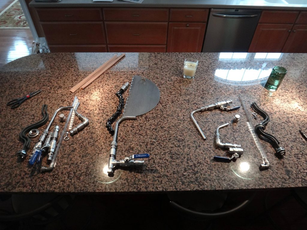
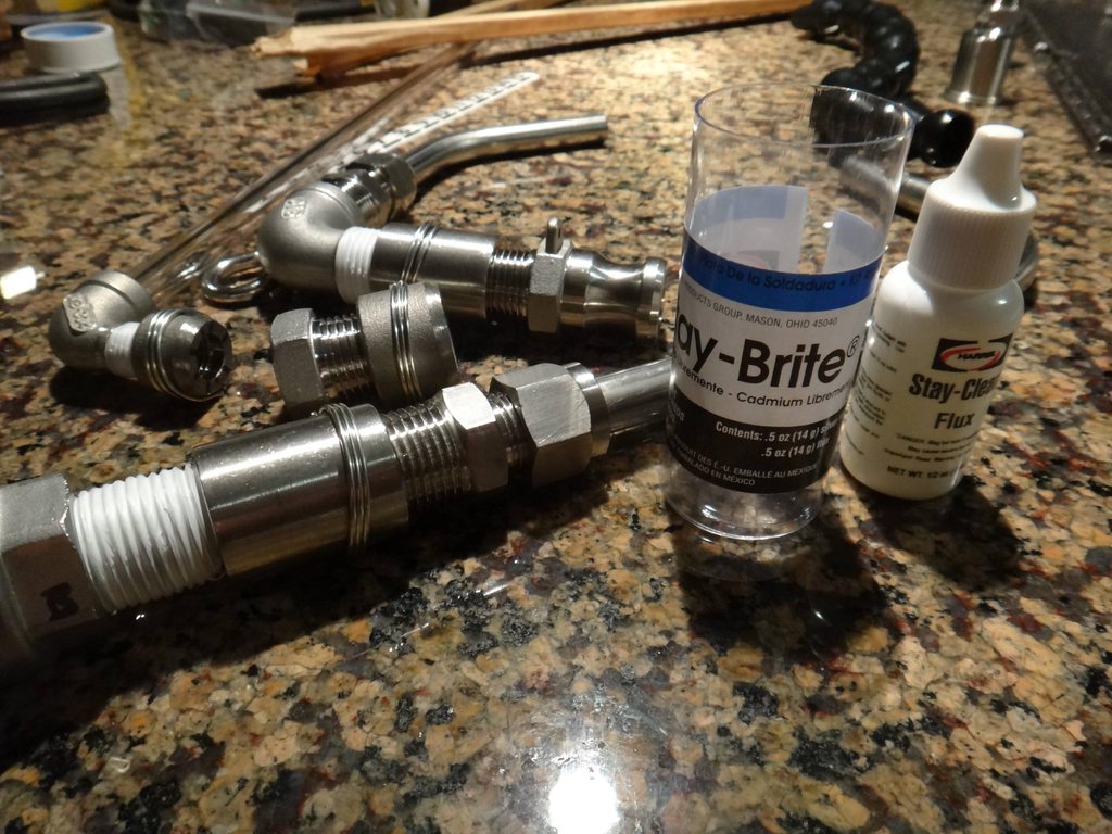
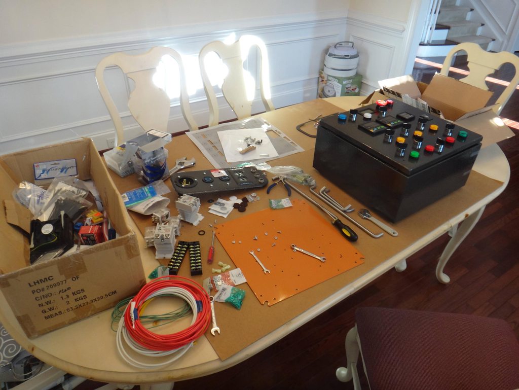
I got all the parts from www.brewhardware.com and www.bargainfittings.com and laid everything out on the counter to make sure everything was in order.
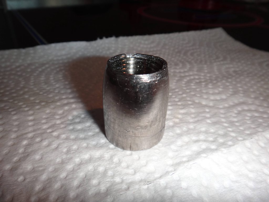
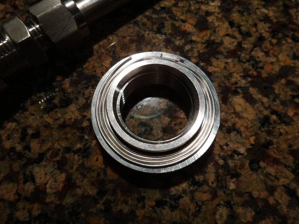
I decided to go with the solder-in-the-couplers method instead of weldless fittings following in the footsteps of a bunch of people in the DIY section. I also decided that I didnt wanna pay the shipping from McMaster to make the dimple tool so I made my own from an extra coupler. I tightened the coupler onto the end of a bolt and then put the bolt in the drill press. I turned the drill press on and used a grinding wheel on my angle grinder to shape the coupler into a cone. Here is the coupler after dimpling all the holes.
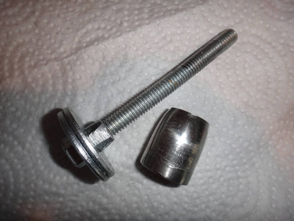
I also modified a nut to fit on the bottom of my guide bolt that would fit perfectly in the wrench side of a standard socket by grinding the nut into a square with the angle grinder. The special nut also helped to hold the socket centered so the coupler pulled through correctly.
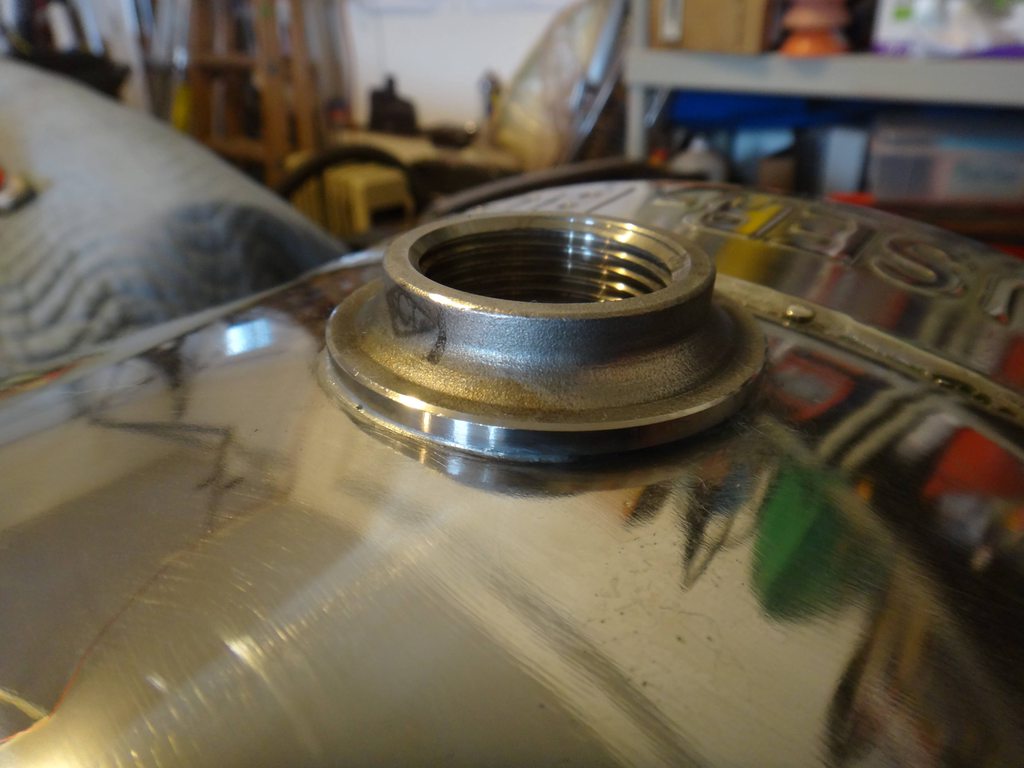
I found that two of the Stay-Brite solder and Flux kits was exactly, to the mm enough to solder in 14 fittings: 10 - 1/2 couplers, 2 1/4 couplers for sight glasses, and 2 1 NPT welding spuds for the heating elements. I portioned everything out to begin with to make sure I had enough solder and everything was in order. I found that three rings of solder around each fitting filled the valley made by the dimple tool perfectly.
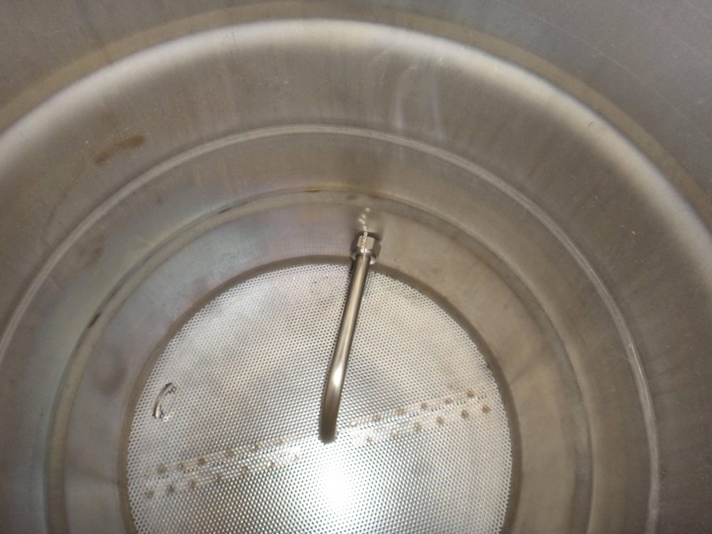
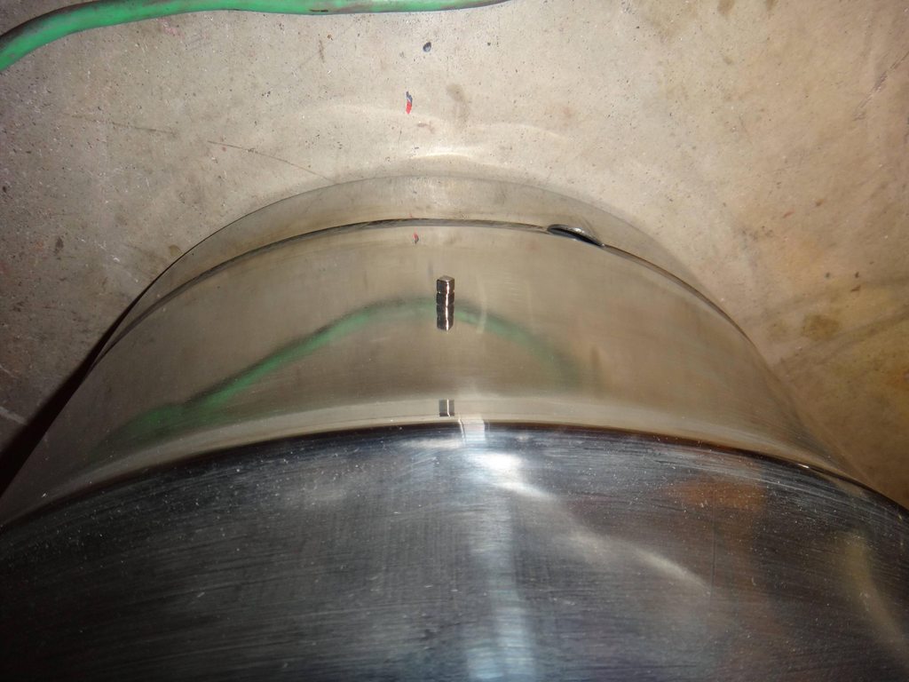
After much thought I decided that the easiest way to position the holes for the dip tubes was to use Bucky Cubes. (They are small super strong magnet cubes that arent available to buy anymore because some moron let their kid eat some and the government shut them down) I put a stack of 3 in the tube and positioned it in the keg where I wanted it, then I used a stack on the outside of the keg to find the ones located on the inside, it worked perfectly. You can see the inside and the outside of the keg in the pictures below, I took the magnets and put them on top of the dip tube for the picture.
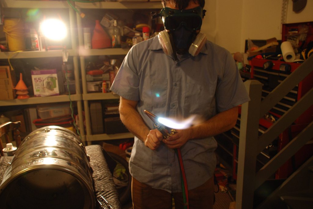
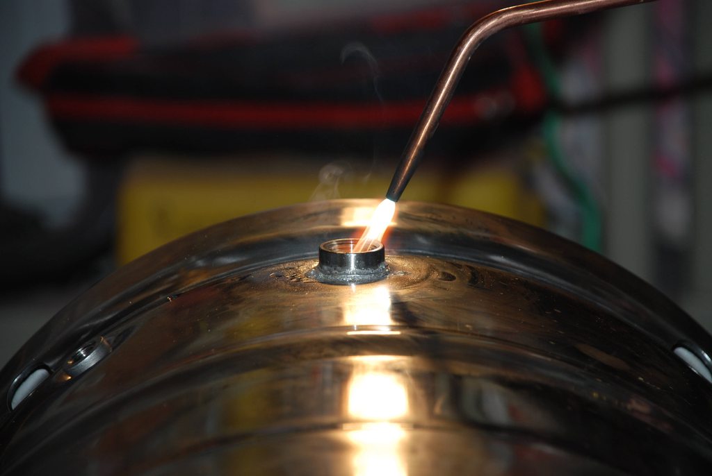
I used an oxy-acetylene torch to solder all the connections. Just make the inner flame long, keep the torch moving constantly and heat the coupler 80% of the time and the keg 20% of the time.
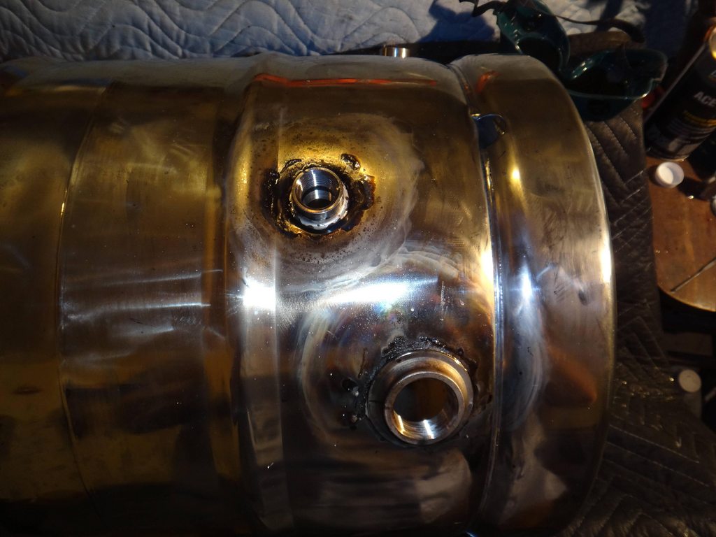
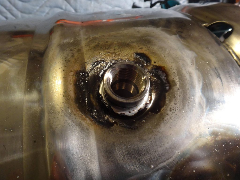
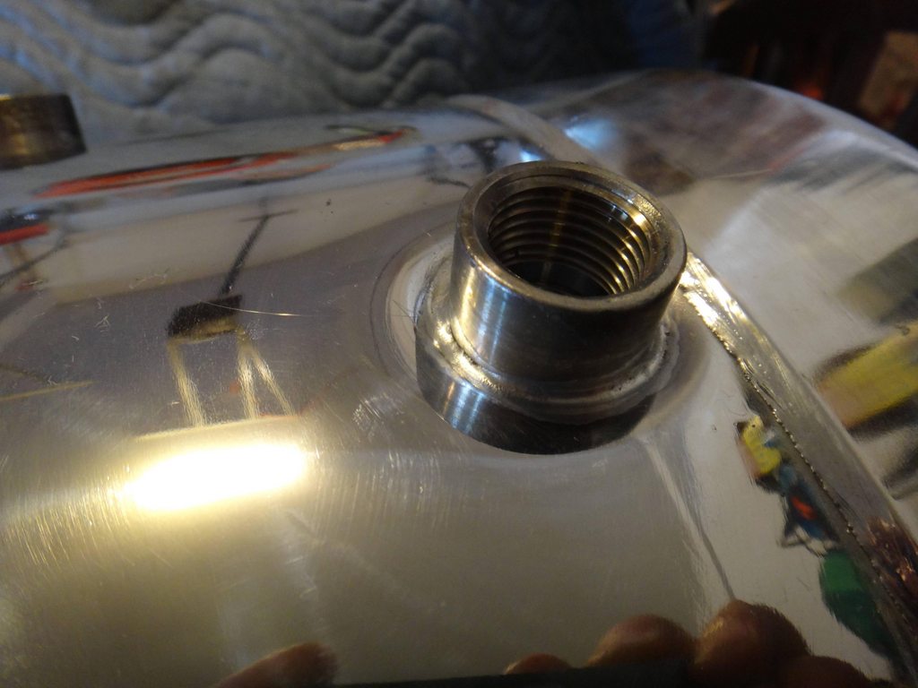
The flux left a ton of residue after the soldering process. I learned that it is very important to let the coupler completely cool before rotating the keg to solder the next connector or the solder will flow with gravity.
A little mineral spirits and some elbow grease and the joints look amazing.
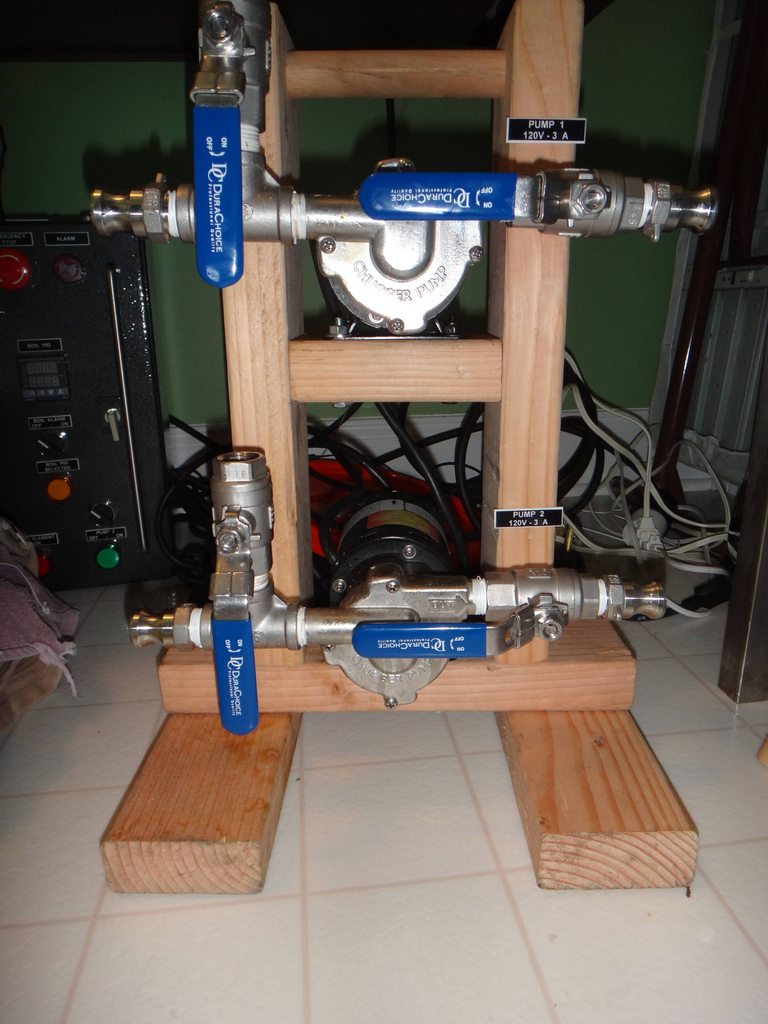
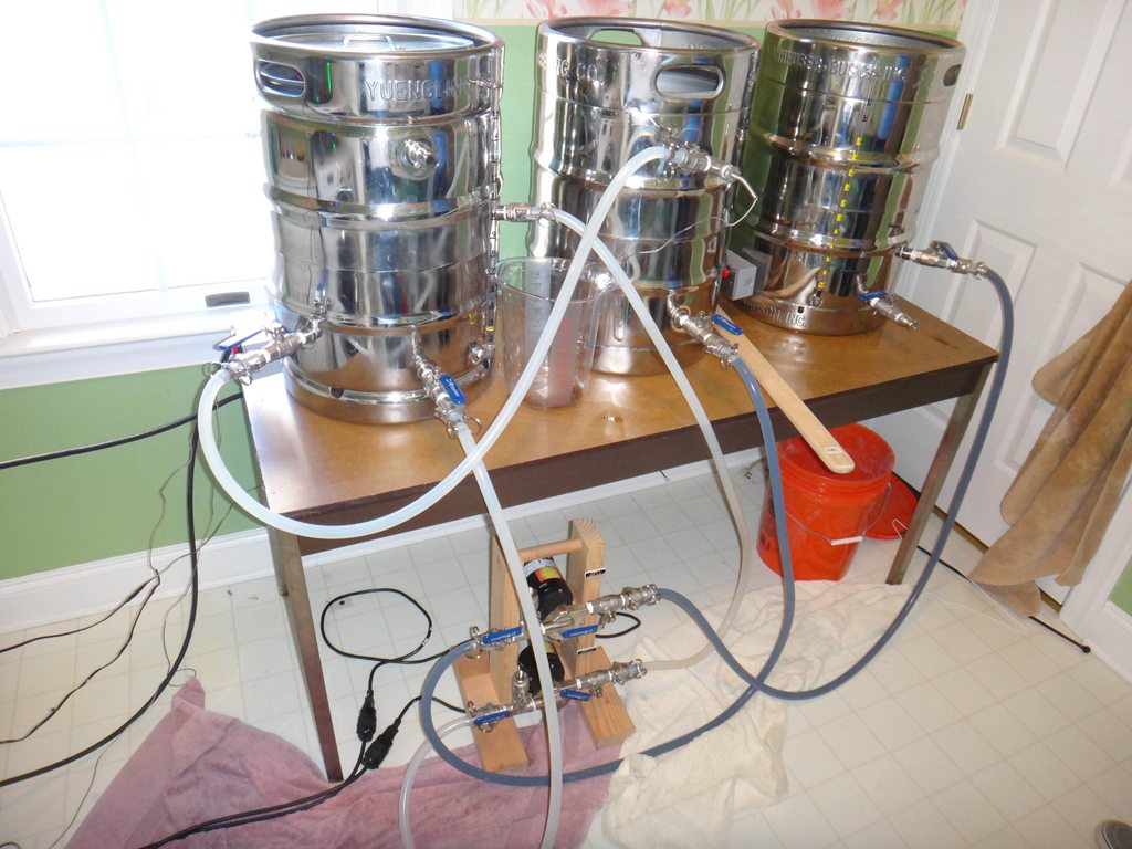
I made a little stand out of wood for my two chugger pumps, I added some valves on the inlet side to bleed the air out. I also put a dowel at the top of the stand to use as a handle.
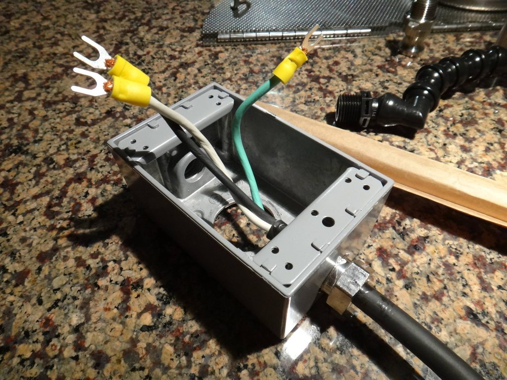
I prepped the junction boxes for the elements, I had some extra 1/4" couplers laying around so I epoxied the wire in place inside the connector and put some quick connectors on the end of the wire to make it easier to install.
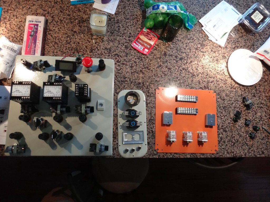
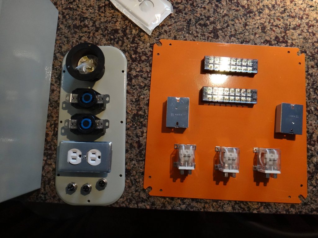
After finishing the modifications on the kegs it was time to start working on the control panel. I ordered all the components from China so it was a little agonizing waiting the weeks for everything to arrive. I finally got everything and placed it all on the plates to make sure everything fit properly.
After mocking everything up I took some exact measurements of the components and the box and made a template in Photoshop to perfectly place everything. I printed the template out at 100%, laminated it, cut everything out with an exacto knife, and traced it all with a sharpie.
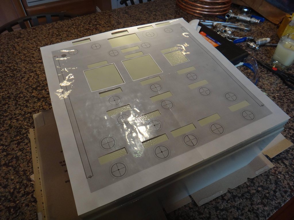
Here is the front panel with the holes drilled, I still need to cut out the PID holes with the dremel.
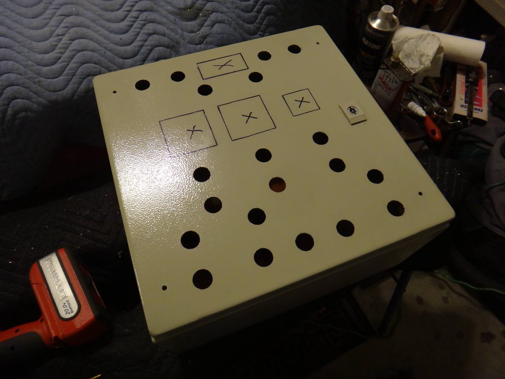
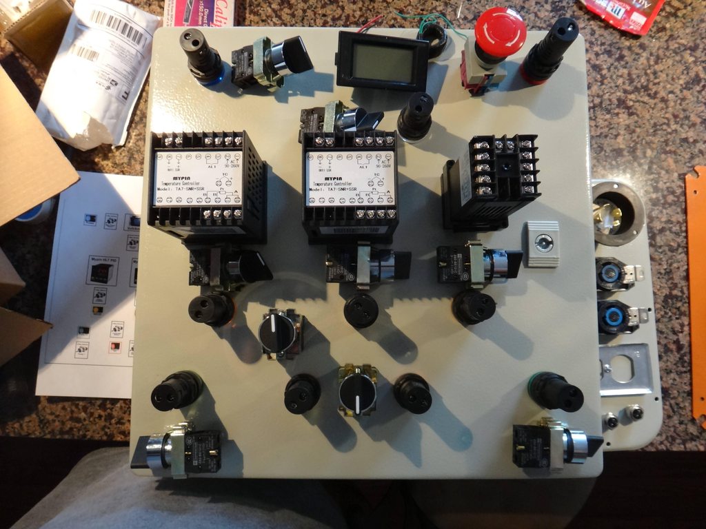
Here is a shot midway through the wiring of the box, I have all the components mounted and have painted the box with the hammered finish.
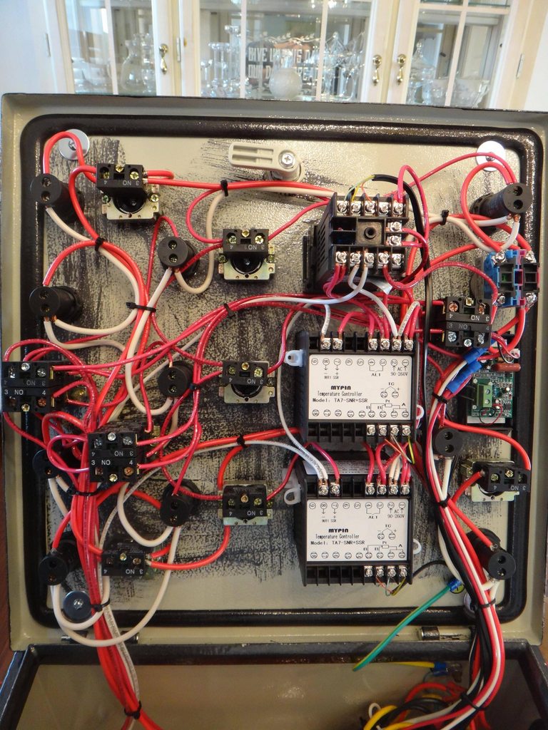
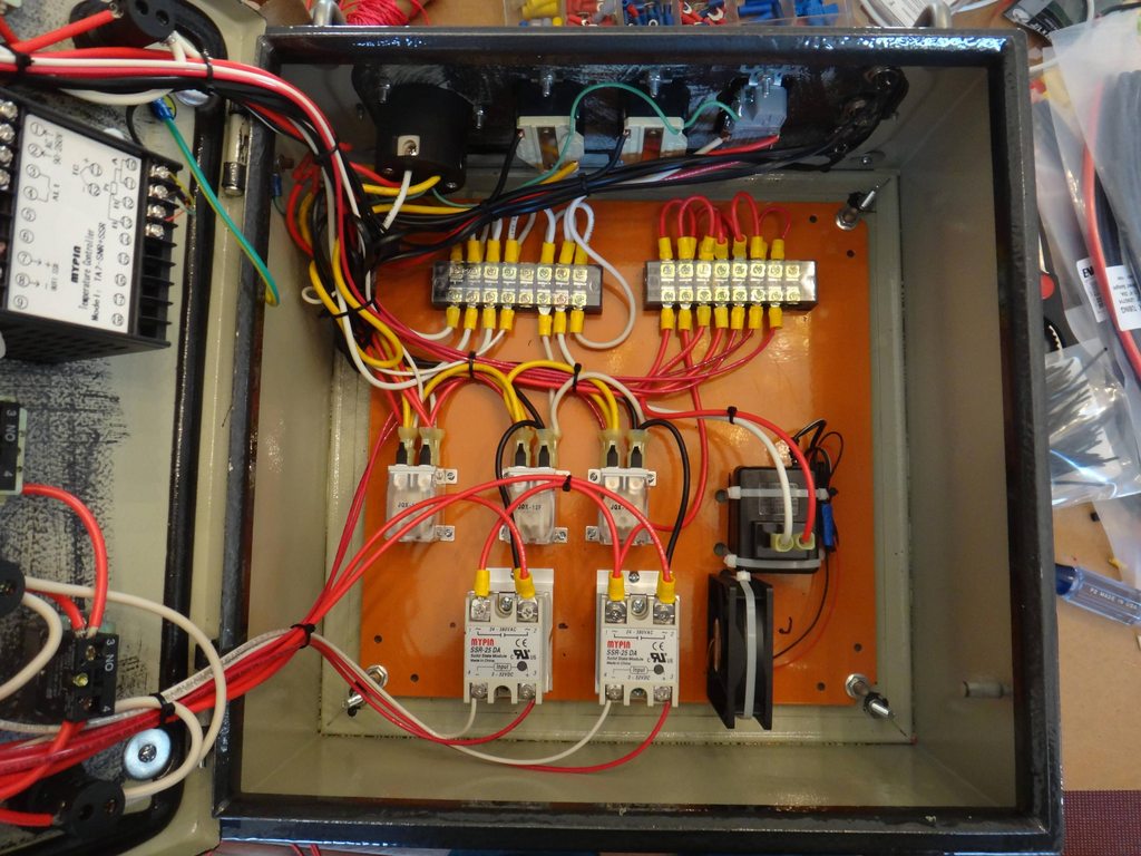
Here are some shots of the inside of the control panel with the wiring all finished.
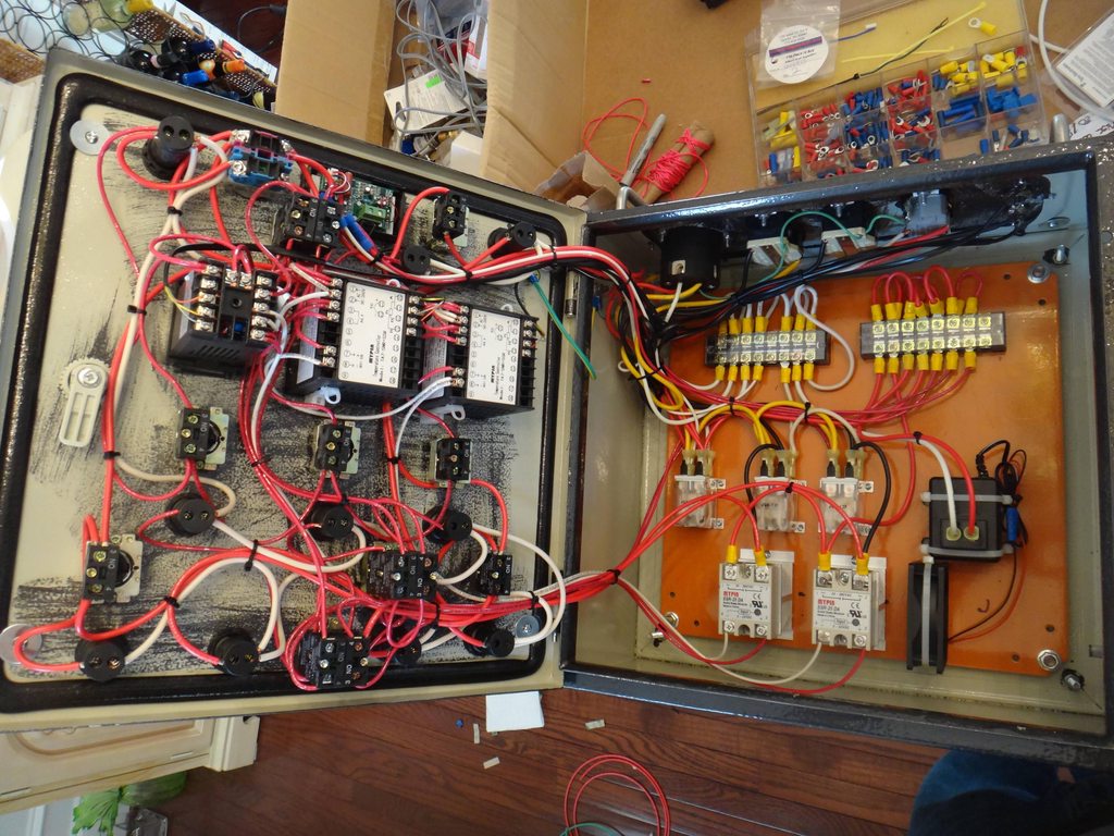
I used some nylon string wrapped around a sharpie and twisted to make it very tight to align the panel labels evenly.
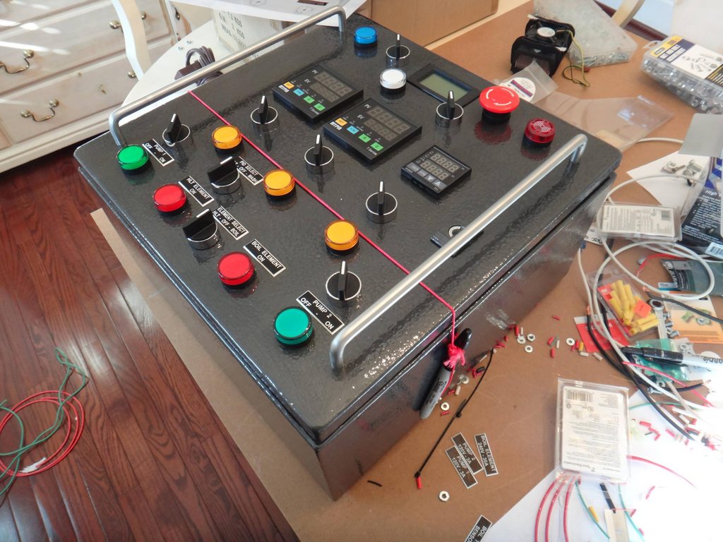
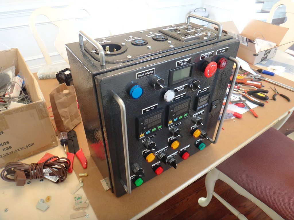
Here are some shots of the completed control box. I have completely changed Kals design while using some of the same components. I will try to explain the functions of everthing as best as possible, but feel free to ask questions.
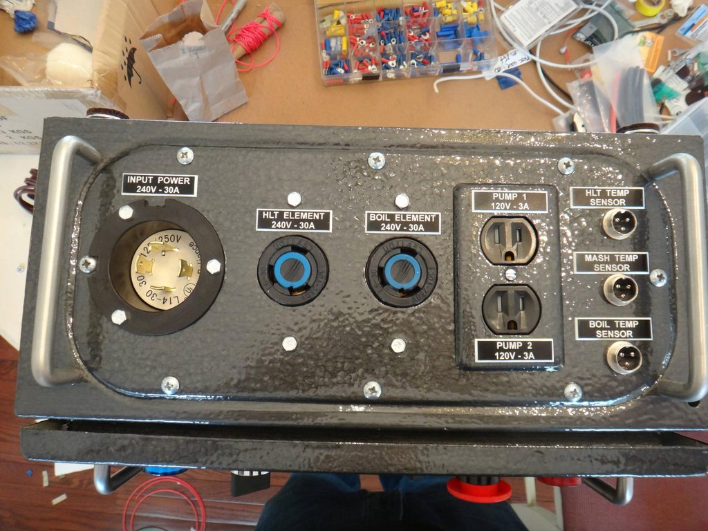
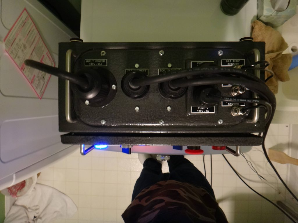
Here is a shot of the port plate on the control panel, there is the main power in, the HLT and Boil element plugs, two separate plugs for the pumps, and the three XLR connectors for the PT100 temperature sensors. Also a corner shot of the finished box.
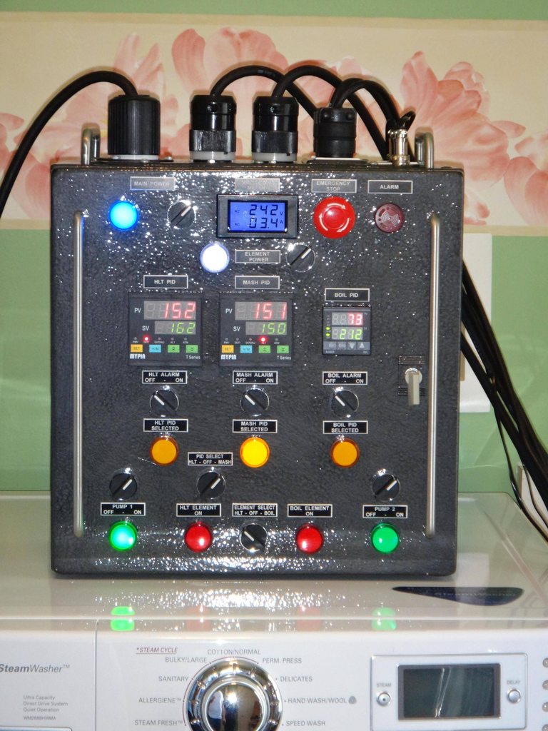
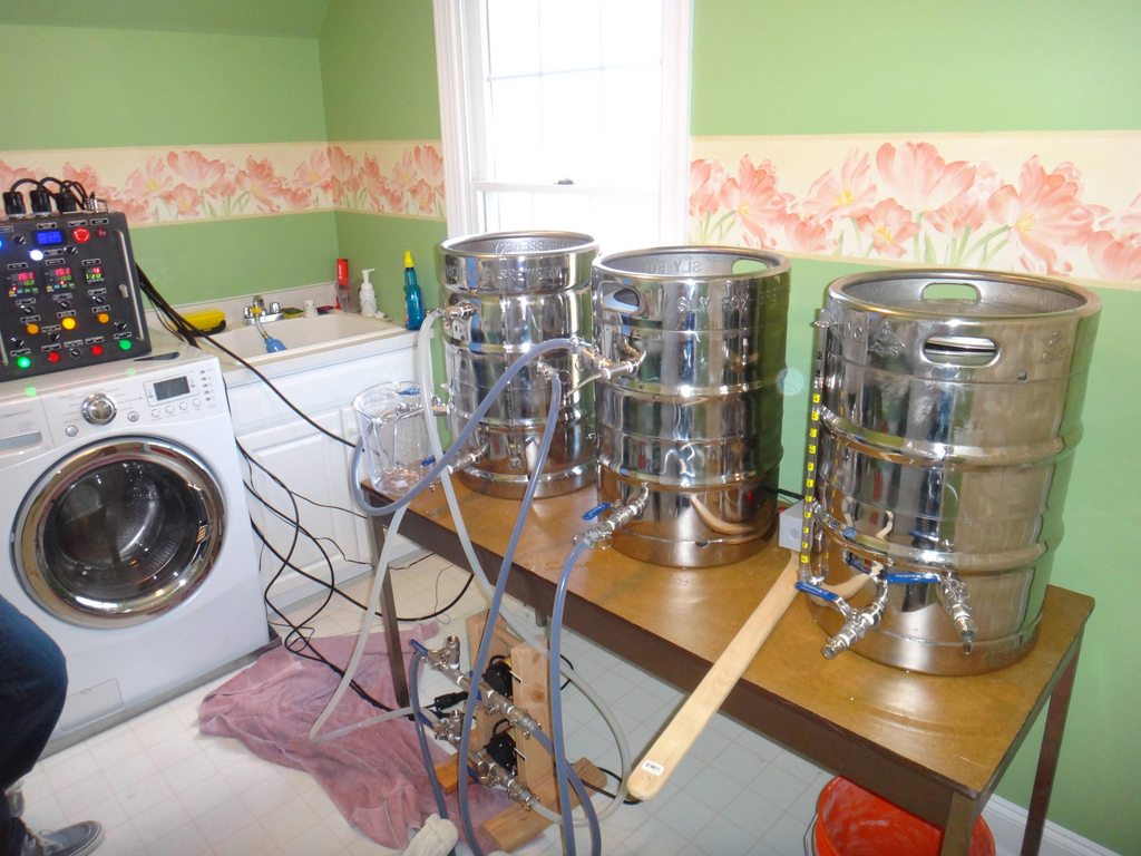
Here is the panel powered up for the first time in a test batch with water.. it didnt explode!! Notice that its sitting on the dryer, thats the only place in the house where we have a 240v outlet, youll see more of that later.
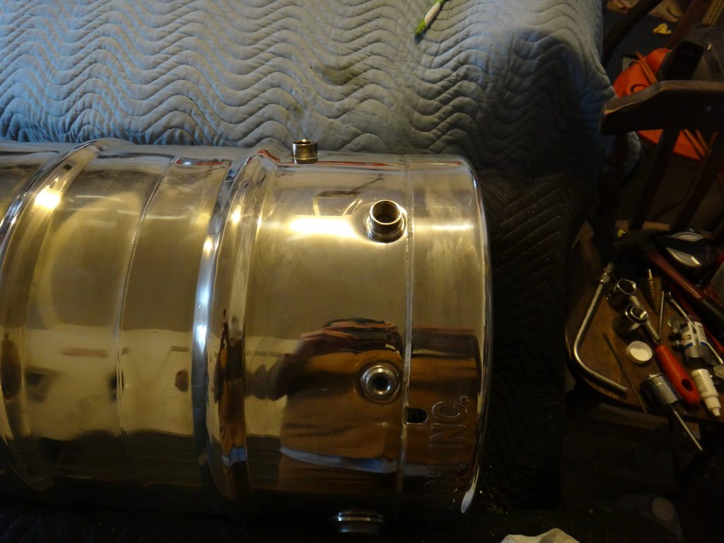
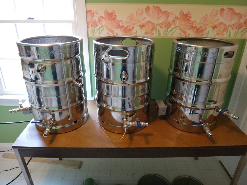
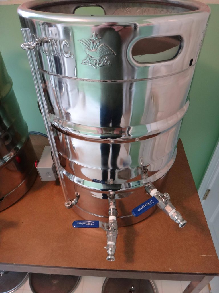
Finished shot of the kegs with soldered connections.
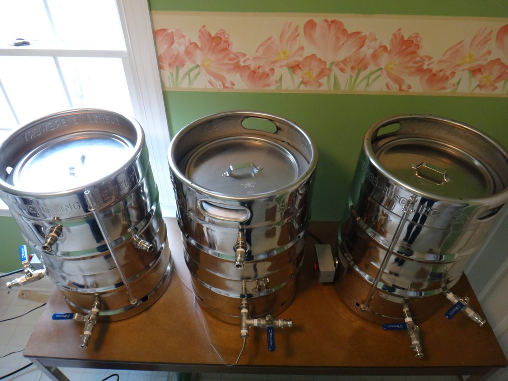
Top shot of the kegs, I got some 12 lids from a restaurant supply store and made sure to cut the holes in the top of the keg so they perfectly fit.
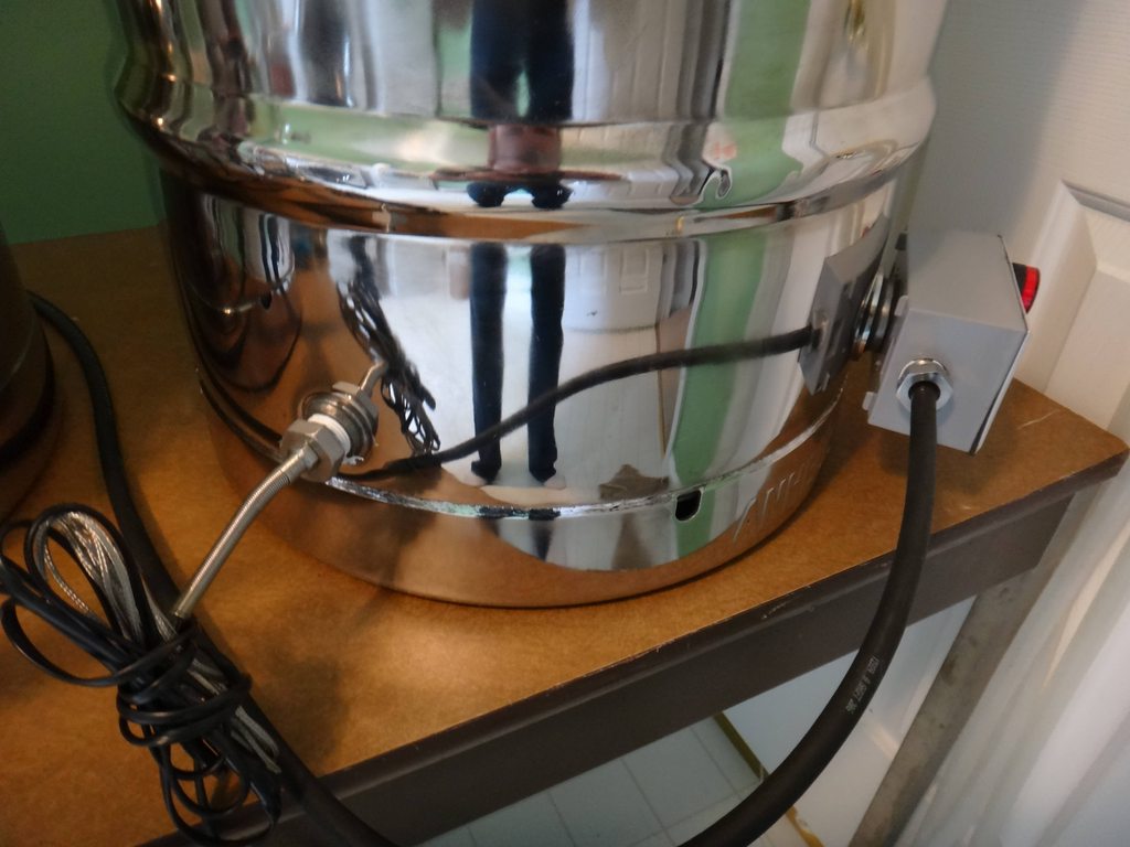
Here is a back shot of the HLT showing the PT100 temp sensor mounted. The one I got had M8x1.0 threads so I had to drill a hole in a plug and tap it to make a custom fitting.
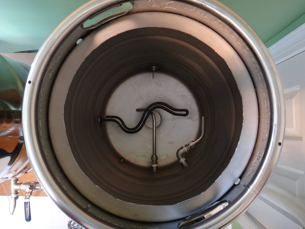
Inside shot of the HLT, You can see the whirlpool arm at the top, the HERMS coil in the middle, the element, the dip tube, and the temp sensor in the back.
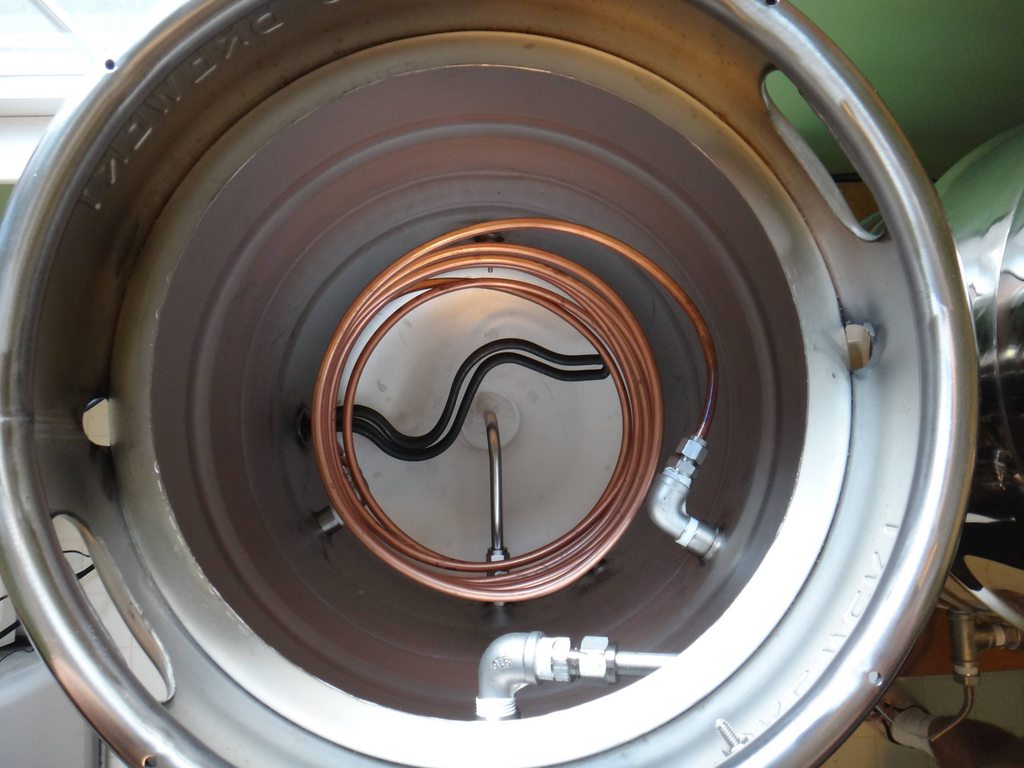
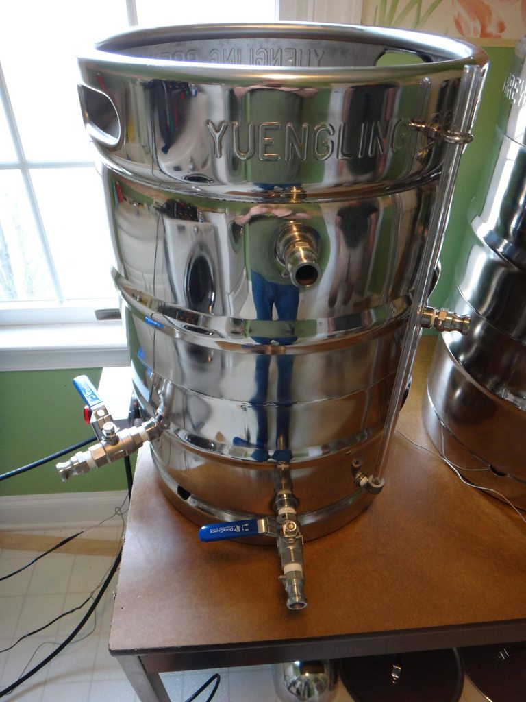
Front shot of the HLT, the left and right fittings are the HERMS coil, the top middle is the whirlpool, and the bottom is the dip tube. You can also see the element junction box on the left in the back... The temp sensor is on the back side of the keggle.
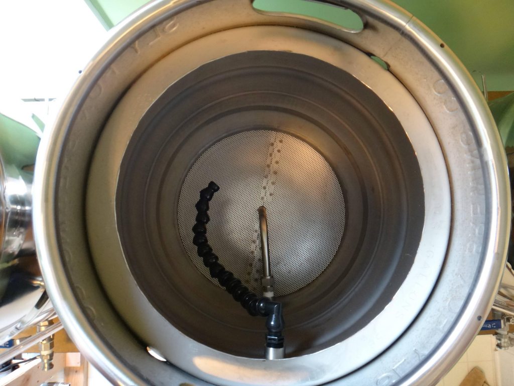
Inside the mash tun, I used brewhardware.com's 15" false bottom and their moveable locline sparage arm.
Front of the mash tun, Notice that the temp sensor for the mash PID is located at the top of the kettle where the sparage arm inlet is.
Inside the boil kettle, you can see the whirpool arm which is placed slightly below the 5gal mark, the 4500w element, and the dip tube that is positioned off-center to not pull the whirlpooled hops, and it really works.
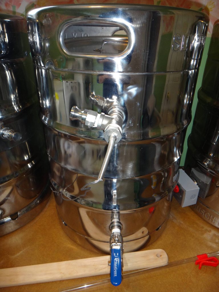
Outside the boil kettle, on the right is the whirlpool arm, in the center is the dip tube.
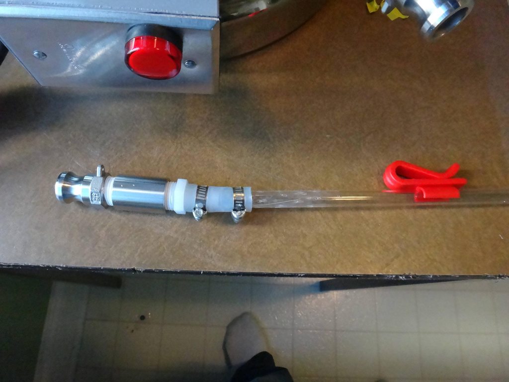
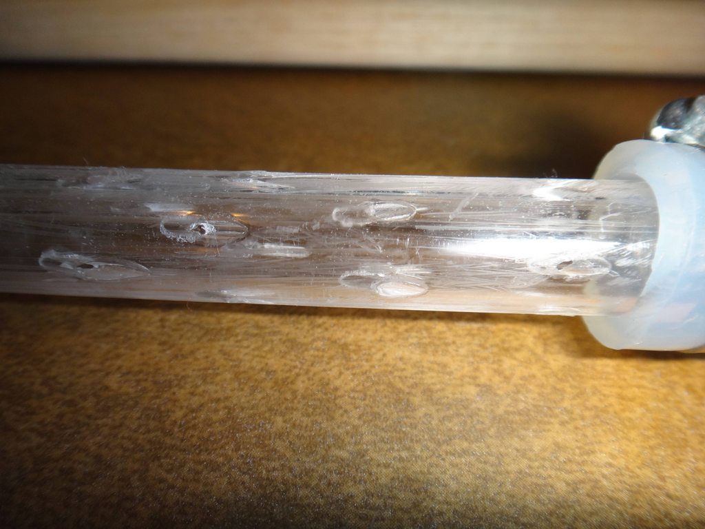
I decided that I needed to aerate my wort after going through this much trouble to make it so I started researching aeration systems. I decided that using a simple verturi system was the easiest and cheapest way to go. I made it out of a 1/2" racking cane I had laying around. I heated up a needle and poked it into the top of the cane and mounted a camlock at the top of it.
Testing the aerator in the HLT with some water.
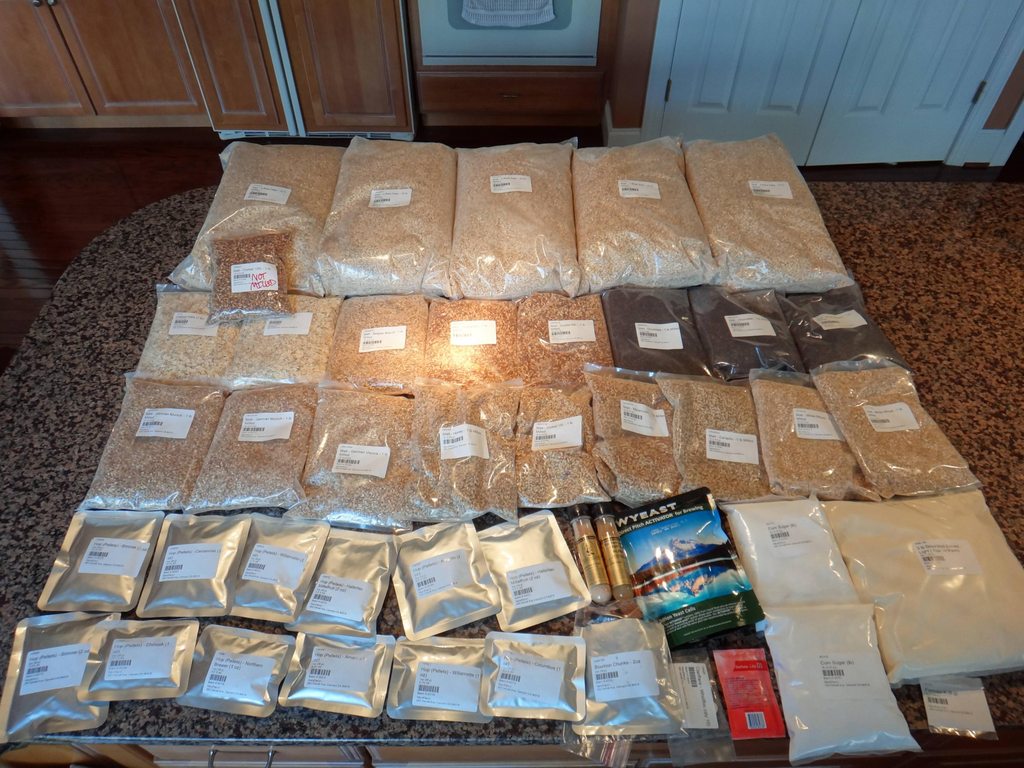
Its go time, here are the ingrediants to make 4 5gal batches of beer a Dragons Milk clone, an Augustiner Helles clone, a Hopslam clone, and a Tiramisu Imperial Stout.
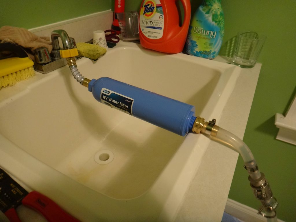
We have city water and it has a kind of earthy flavor so I decided to filter it. I got an RV inline water filter and connected it to my slop sink in the laundry room and a hose to camlock adapter I made. Here it is filling up the HLT at the beginning of the first brewday.
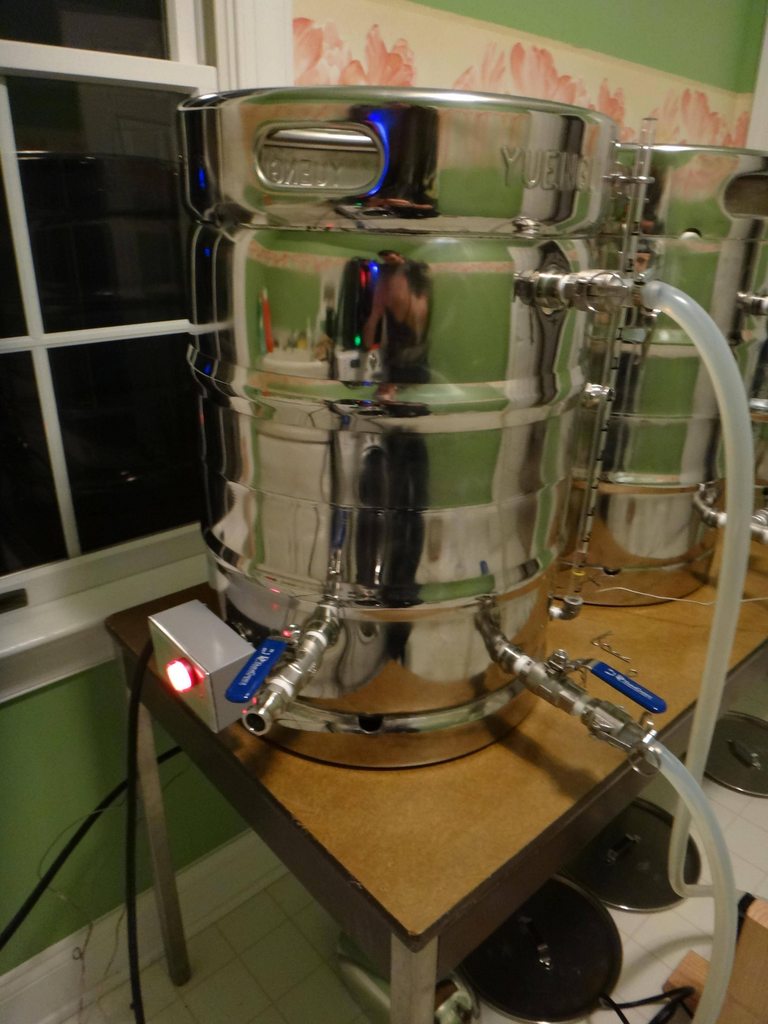
Here is a shot of the HLT heating up the water to strike temp. Notice that I installed a 220v LED to the junction box on the kettle, this allows me to see if the element is on just by looking at the kettle.
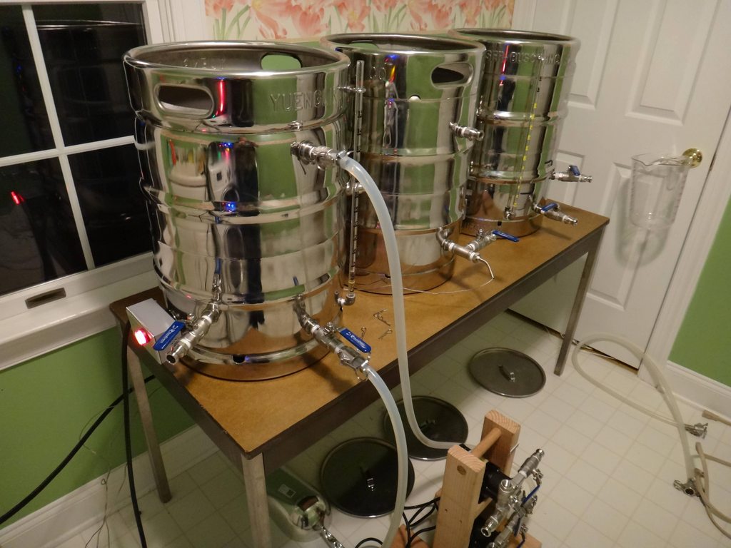
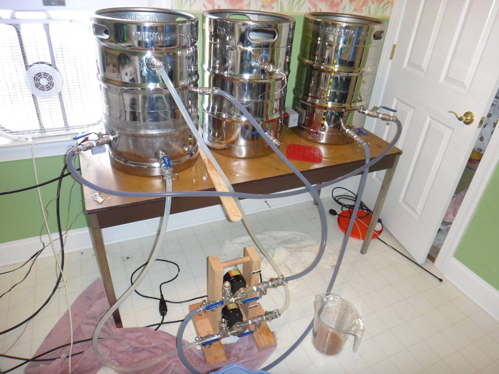
Whole system view of the HLT heating the water, notice the chugger pump is recirculating the water in the HLT to ensure an even temp.
Grain in the mash tun, I got the mash paddle from the restaurant supply place for $8!
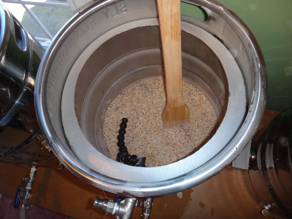
Mash in.
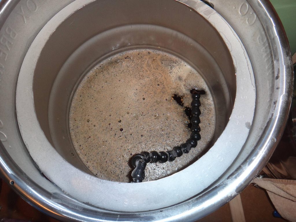
This is halfway through the mash, the wort is recirculating through the HERMS coil and the water in the HLT is recirculating while the PID on the control panel is controlling the temp coming into the Mash Tun by firing the HLT element. Notice that the Mash PID controller is selected as indicated by the center yellow LED on the control panel.
Sparage step, Pump 1 is pulling the wort into the boil kettle, and pump 2 is pulling strike water from the HLT to the Mash Tun.
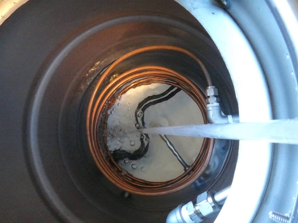
Post boil cooling, The HLT is now filled with ice water and the hot wort is circulating through the HERMS coil.
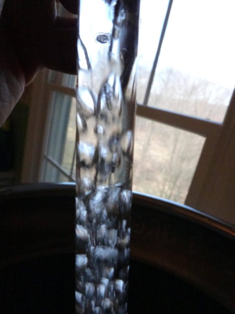
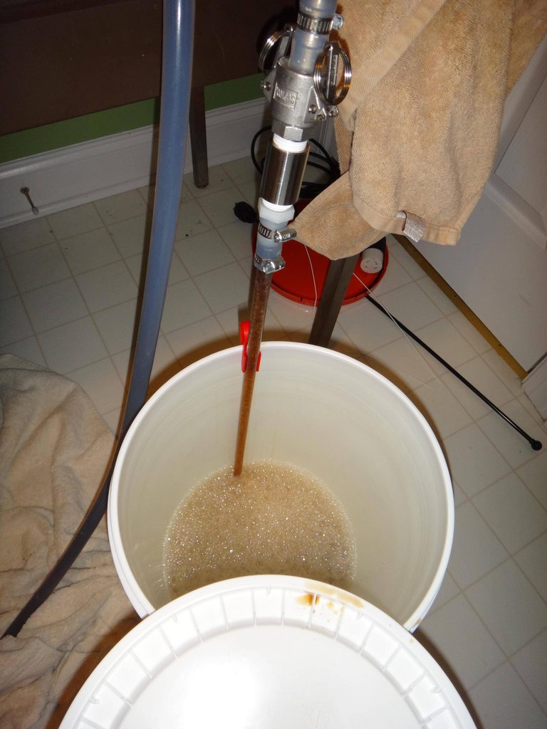
Transferring into the fermenter, you can see the venturi in action.
Mid-brewday picture, Im on the right, my friend from PSU wanted to come witness the systems maiden voyage. Shout out to Zenos Pub in State College, PA (notice the shirts) for starting me on my beer obsession.

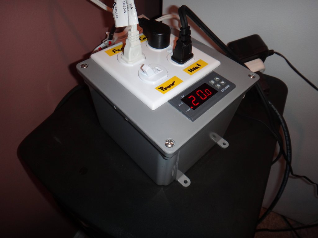
I also made a fermentation controller out of a STC-1000 a project box from Home Depot and some switches and plugs. I added a switch to kill all the power, an always on plug, and a plug for the heating circuit and the cooling circuit.
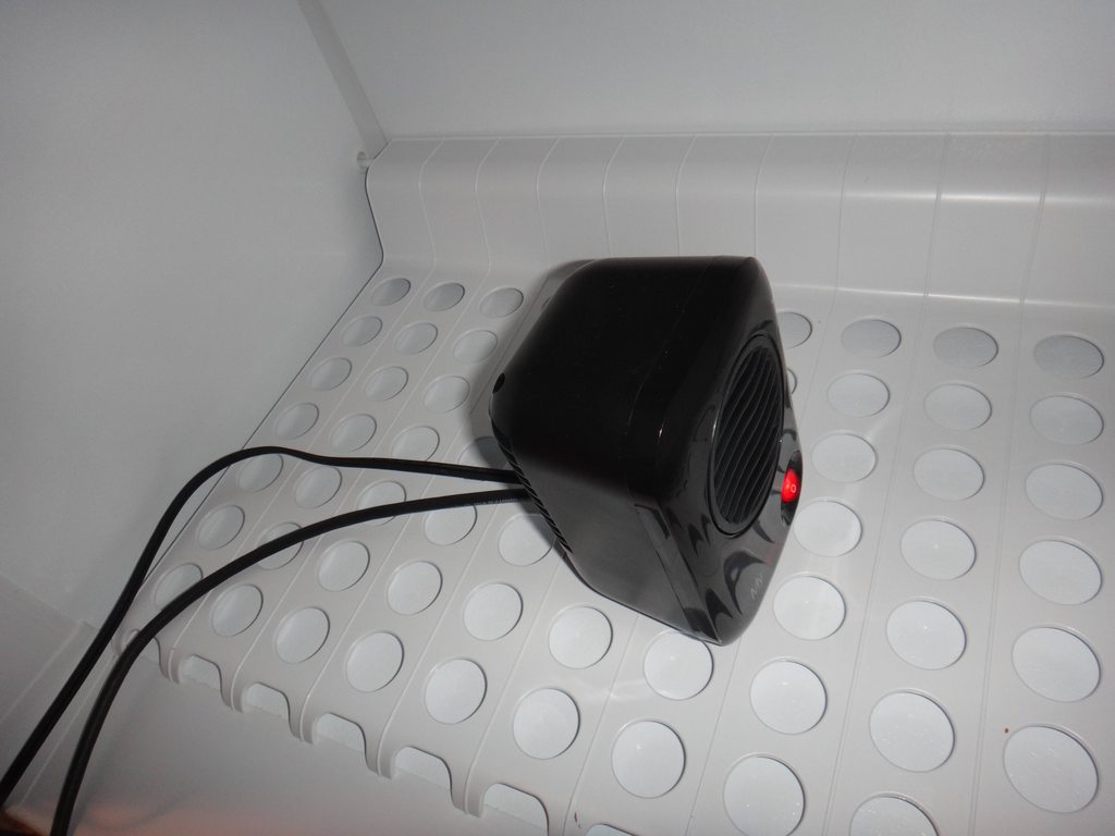
I found this really cool mini space heater in Walmart for like $12. I opened it up and installed separate wires for the heater and the fan. I can plug the fan into the always on circuit and the heating element into the heat controlled outlet on my controller box.
Made a stir plate out of a tupperware container, a computer fan, hard drive magnet, and potentiometer from Radio Shack. I got lazy at this point and just hot glued everything together, haha.
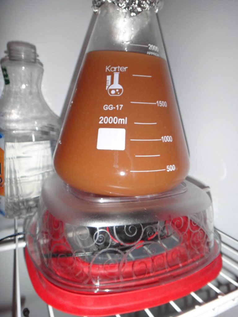
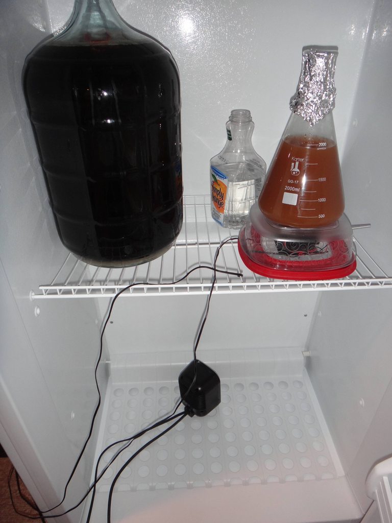
Picture of the ferm chamber with a starter on the stir plate, the first batch in the secondary, and a bottle of StarSan water for the blowoff.
And thats about it, thanks again for all the info on here.. Im sure there will be questions, fire away
Alex.
I would like to start by saying thank you to everyone on this forum, the wealth of knowledge on here is incredible, I couldnt have done it without you guys.
I started my brewing journey last Christmas when my girlfriend got me the Midwest beginners kit in the Irish Stout variety.. It was all uphill from there (downhill financially lol). After brewing about 8 extract batches I decided to step it up a bit, and being an engineer I am unable to half-ass anything and so starts my build.
I made an immersion wort chiller out of copper for my extract batches and because of that after much research and reading about everything I decided to go with an E-HERMS system using my chiller as the heat exchanger coil.
I managed to get three kegs from the local distributer for the deposit and spent over 50 hours polishing all three of them. It was a terrible experience but I guess in the end they look nice and it was sorta kinda worth it.. maybe?
I got all the parts from www.brewhardware.com and www.bargainfittings.com and laid everything out on the counter to make sure everything was in order.
I decided to go with the solder-in-the-couplers method instead of weldless fittings following in the footsteps of a bunch of people in the DIY section. I also decided that I didnt wanna pay the shipping from McMaster to make the dimple tool so I made my own from an extra coupler. I tightened the coupler onto the end of a bolt and then put the bolt in the drill press. I turned the drill press on and used a grinding wheel on my angle grinder to shape the coupler into a cone. Here is the coupler after dimpling all the holes.
I also modified a nut to fit on the bottom of my guide bolt that would fit perfectly in the wrench side of a standard socket by grinding the nut into a square with the angle grinder. The special nut also helped to hold the socket centered so the coupler pulled through correctly.
I found that two of the Stay-Brite solder and Flux kits was exactly, to the mm enough to solder in 14 fittings: 10 - 1/2 couplers, 2 1/4 couplers for sight glasses, and 2 1 NPT welding spuds for the heating elements. I portioned everything out to begin with to make sure I had enough solder and everything was in order. I found that three rings of solder around each fitting filled the valley made by the dimple tool perfectly.
After much thought I decided that the easiest way to position the holes for the dip tubes was to use Bucky Cubes. (They are small super strong magnet cubes that arent available to buy anymore because some moron let their kid eat some and the government shut them down) I put a stack of 3 in the tube and positioned it in the keg where I wanted it, then I used a stack on the outside of the keg to find the ones located on the inside, it worked perfectly. You can see the inside and the outside of the keg in the pictures below, I took the magnets and put them on top of the dip tube for the picture.
I used an oxy-acetylene torch to solder all the connections. Just make the inner flame long, keep the torch moving constantly and heat the coupler 80% of the time and the keg 20% of the time.
The flux left a ton of residue after the soldering process. I learned that it is very important to let the coupler completely cool before rotating the keg to solder the next connector or the solder will flow with gravity.
A little mineral spirits and some elbow grease and the joints look amazing.
I made a little stand out of wood for my two chugger pumps, I added some valves on the inlet side to bleed the air out. I also put a dowel at the top of the stand to use as a handle.
I prepped the junction boxes for the elements, I had some extra 1/4" couplers laying around so I epoxied the wire in place inside the connector and put some quick connectors on the end of the wire to make it easier to install.
After finishing the modifications on the kegs it was time to start working on the control panel. I ordered all the components from China so it was a little agonizing waiting the weeks for everything to arrive. I finally got everything and placed it all on the plates to make sure everything fit properly.
After mocking everything up I took some exact measurements of the components and the box and made a template in Photoshop to perfectly place everything. I printed the template out at 100%, laminated it, cut everything out with an exacto knife, and traced it all with a sharpie.
Here is the front panel with the holes drilled, I still need to cut out the PID holes with the dremel.
Here is a shot midway through the wiring of the box, I have all the components mounted and have painted the box with the hammered finish.
Here are some shots of the inside of the control panel with the wiring all finished.
I used some nylon string wrapped around a sharpie and twisted to make it very tight to align the panel labels evenly.
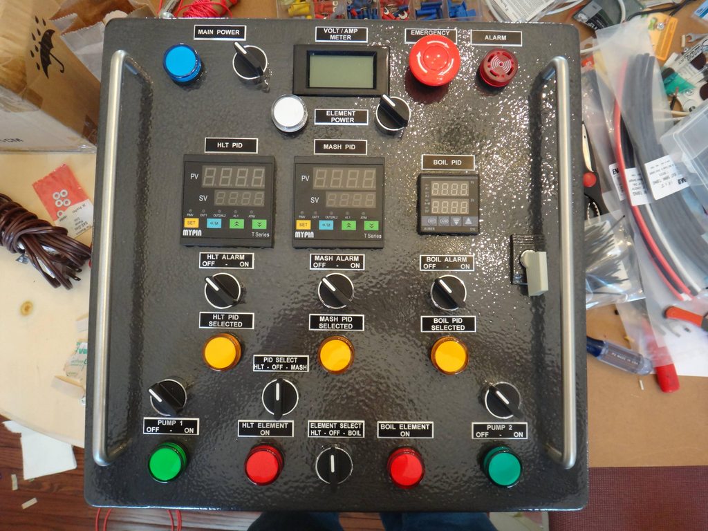
Here are some shots of the completed control box. I have completely changed Kals design while using some of the same components. I will try to explain the functions of everthing as best as possible, but feel free to ask questions.
- Starting from the top row we have the main power on the left with an indicator light.
- A combination volt and amp meter in the middle that does not require any special power supply.
- An emergency stop button that cuts the power to the main hardware relay and is wired inline with the main power switch, the emergency stop button will also sound the alarm buzzer.
- The next row down is a switch and an indicator light for the element power this switch works as a master switch for the elements, this way the elements can be prevented from firing while the box is still energized. I wanted this just as an added precaution.
- The next row down are the PIDs one for the HLT, Mash, and the Boil kettle. I got the Mypins off newegg because I had a gift card and I got the Auber for the Boil kettle because of its PWM functions.
- The next row down are the switches for the PID alarms, these will also sound the alarm buzzer on the top row.
- The next row down is an indicator light showing which PID currently has control of the element and therefore which one is currently selected.
- The next row down has the switches for the two pumps and a switch for selecting between the HLT and Mash PIDs. The way my system is designed there is a heating element that is in the HLT and one in the Boil kettle, this switch selects which PID controls the HLT element, in order for this switch to be active the switch in the next row down labeled element select needs to be set to HLT. This will be explained more below.
- The next row down has the indicators for the pumps, the indicators for when the element is actually energized and the selector switch to switch between the element in the HLT and the Boil kettle.
Here is a shot of the port plate on the control panel, there is the main power in, the HLT and Boil element plugs, two separate plugs for the pumps, and the three XLR connectors for the PT100 temperature sensors. Also a corner shot of the finished box.
Here is the panel powered up for the first time in a test batch with water.. it didnt explode!! Notice that its sitting on the dryer, thats the only place in the house where we have a 240v outlet, youll see more of that later.
Finished shot of the kegs with soldered connections.
Top shot of the kegs, I got some 12 lids from a restaurant supply store and made sure to cut the holes in the top of the keg so they perfectly fit.
Here is a back shot of the HLT showing the PT100 temp sensor mounted. The one I got had M8x1.0 threads so I had to drill a hole in a plug and tap it to make a custom fitting.
Inside shot of the HLT, You can see the whirlpool arm at the top, the HERMS coil in the middle, the element, the dip tube, and the temp sensor in the back.
Front shot of the HLT, the left and right fittings are the HERMS coil, the top middle is the whirlpool, and the bottom is the dip tube. You can also see the element junction box on the left in the back... The temp sensor is on the back side of the keggle.
Inside the mash tun, I used brewhardware.com's 15" false bottom and their moveable locline sparage arm.
Front of the mash tun, Notice that the temp sensor for the mash PID is located at the top of the kettle where the sparage arm inlet is.
Inside the boil kettle, you can see the whirpool arm which is placed slightly below the 5gal mark, the 4500w element, and the dip tube that is positioned off-center to not pull the whirlpooled hops, and it really works.
Outside the boil kettle, on the right is the whirlpool arm, in the center is the dip tube.
I decided that I needed to aerate my wort after going through this much trouble to make it so I started researching aeration systems. I decided that using a simple verturi system was the easiest and cheapest way to go. I made it out of a 1/2" racking cane I had laying around. I heated up a needle and poked it into the top of the cane and mounted a camlock at the top of it.
Testing the aerator in the HLT with some water.
Its go time, here are the ingrediants to make 4 5gal batches of beer a Dragons Milk clone, an Augustiner Helles clone, a Hopslam clone, and a Tiramisu Imperial Stout.
We have city water and it has a kind of earthy flavor so I decided to filter it. I got an RV inline water filter and connected it to my slop sink in the laundry room and a hose to camlock adapter I made. Here it is filling up the HLT at the beginning of the first brewday.
Here is a shot of the HLT heating up the water to strike temp. Notice that I installed a 220v LED to the junction box on the kettle, this allows me to see if the element is on just by looking at the kettle.
Whole system view of the HLT heating the water, notice the chugger pump is recirculating the water in the HLT to ensure an even temp.
Grain in the mash tun, I got the mash paddle from the restaurant supply place for $8!
Mash in.
This is halfway through the mash, the wort is recirculating through the HERMS coil and the water in the HLT is recirculating while the PID on the control panel is controlling the temp coming into the Mash Tun by firing the HLT element. Notice that the Mash PID controller is selected as indicated by the center yellow LED on the control panel.
Sparage step, Pump 1 is pulling the wort into the boil kettle, and pump 2 is pulling strike water from the HLT to the Mash Tun.
Post boil cooling, The HLT is now filled with ice water and the hot wort is circulating through the HERMS coil.
Transferring into the fermenter, you can see the venturi in action.
Mid-brewday picture, Im on the right, my friend from PSU wanted to come witness the systems maiden voyage. Shout out to Zenos Pub in State College, PA (notice the shirts) for starting me on my beer obsession.
I also made a fermentation controller out of a STC-1000 a project box from Home Depot and some switches and plugs. I added a switch to kill all the power, an always on plug, and a plug for the heating circuit and the cooling circuit.
I found this really cool mini space heater in Walmart for like $12. I opened it up and installed separate wires for the heater and the fan. I can plug the fan into the always on circuit and the heating element into the heat controlled outlet on my controller box.
Made a stir plate out of a tupperware container, a computer fan, hard drive magnet, and potentiometer from Radio Shack. I got lazy at this point and just hot glued everything together, haha.
Picture of the ferm chamber with a starter on the stir plate, the first batch in the secondary, and a bottle of StarSan water for the blowoff.
And thats about it, thanks again for all the info on here.. Im sure there will be questions, fire away
Alex.
")

