ebay aquarium temp controller build

Homebrew Talk - Beer, Wine, Mead, & Cider Brewing Discussion Forum

Help Support Homebrew Talk - Beer, Wine, Mead, & Cider Brewing Discussion Forum:

This site may earn a commission from merchant affiliate links, including eBay, Amazon, and others.
I just read this entire thread and still am a little bit confused being a total electricity noob... could someone help me out here?

I'm planning on buying the ebay controller and using a cut up heavy duty extension cord for all the wiring. I want to use it only for one stage (cooling) but also want to power a fan whenever the cooling turns on.

My understanding is that I can just NOT break any tabs off, then I can just plug in both the fridge and a computer fan (wired up to a cell phone charger) and both will fire at the same time.

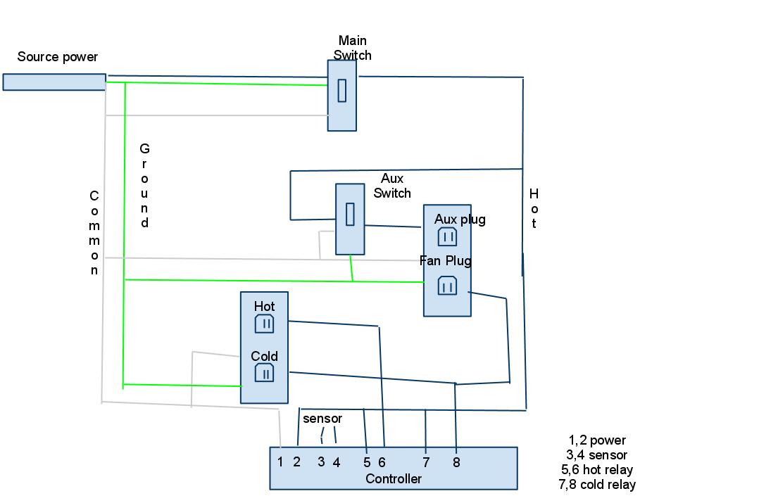
That brings me to my next question... I modified the diagram from the OP to what I think would be correct for my purpose... make sense?

diagramf.jpg


It's electricity so I want to be as sure as possible that I'm doing it right before I start playing with wires.

Something else you could do is build the controller like everyone else has been talking about and make a hot/cold just in case you decide you want to use a brew belt or something in the future. In the mean time get one of those 3 outlet adapters to plug into your cold outlet and plug your freezer and fan into that.
 
I made mine with two seperate receptacles, one for hot one for cold. But i have two seperate fans, so it just made sense to do it that way.
 
What size project box is that? Just got my controller but my local radio shack doesn't carry the project boxes that are big enough and I forgot to measure the thing before I left the house haha
 
What size project box is that? Just got my controller but my local radio shack doesn't carry the project boxes that are big enough and I forgot to measure the thing before I left the house haha

I bought a small clear plastic box from Ace Hardware for $2.50. Cheaper than any project box you'll find at Radio Shack.
 
I am using a Rubbermaid box I think was purposed for some type of cataloging. it was fifty cents from the goodwill.

-=Jason=-
 
So, I wired up the circuit like so:

EkMuC.jpg


And every time I switched on the main power, it tripped the breaker. I removed the switches, and everything works perfectly.

Why are the switches causing the breaker to be tripped?
 
So, I wired up the circuit like so:
And every time I switched on the main power, it tripped the breaker. I removed the switches, and everything works perfectly.

Why are the switches causing the breaker to be tripped?

This is just a guess, since you may have a switch that needs hot and neutral for some reason, but usually the switch just switches one leg. The additional post that may/may not be there is for "pass through" of a leg to run to another device. It looks like you wired hot to one and neutral to another which is causing a direct hot-neutral circuit, and the breaker to trip.

Where did you get that schematic?

Also a guess, but I think his switches might be illuminated, so they need a additional connections for the lights inside.

I use illuminated switches on my electric brewery panel that need only a 3rd connection for a neutral.

But, if his switches have 4 connection points on them, then there could be a lot of things going on. They could be 2-pole switches, or they could be illuminated ones that are supposed to be getting a separate low voltage DC supplyl for the lamps in them.

A link to see details about the switches would be very helpful.

edit: But I do think you are right that the switches are wired in incorrectly and are creating a short circuit from hot to neutral.
 
Something else you could do is build the controller like everyone else has been talking about and make a hot/cold just in case you decide you want to use a brew belt or something in the future. In the mean time get one of those 3 outlet adapters to plug into your cold outlet and plug your freezer and fan into that.

This is a good point. I'm going to be shoving my box in a small space though, I don't want an outlet adapter sticking out. I definitely won't be needing heat for a long time, I'll be in this apartment for at least a couple more years... I figure if I hook everything up to just the top outlet later on I can just break the tabs and it'd be a really simple task to make the bottom one heat.
 
This is just a guess, since you may have a switch that needs hot and neutral for some reason, but usually the switch just switches one leg. The additional post that may/may not be there is for "pass through" of a leg to run to another device. It looks like you wired hot to one and neutral to another which is causing a direct hot-neutral circuit, and the breaker to trip.

Where did you get that schematic?

I just bought the switches at Ace. I thought I bought the most basic switches. I just wired them up going off the text on the posts.

I made the schematic.
 
Also a guess, but I think his switches might be illuminated, so they need a additional connections for the lights inside.

I use illuminated switches on my electric brewery panel that need only a 3rd connection for a neutral.

But, if his switches have 4 connection points on them, then there could be a lot of things going on. They could be 2-pole switches, or they could be illuminated ones that are supposed to be getting a separate low voltage DC supplyl for the lamps in them.

A link to see details about the switches would be very helpful.

edit: But I do think you are right that the switches are wired in incorrectly and are creating a short circuit from hot to neutral.

They are not illuminated switches. I think I bought 3 way switches. Because they have no on/off markings.

http://homerepair.about.com/od/electricalrepair/ss/switch_types_4.htm

Stupid me. Thanks for helping me out and getting me to look at what type of switch I actually bought.
 
But, if his switches have 4 connection points on them, then there could be a lot of things going on. They could be 2-pole switches, or they could be illuminated ones that are supposed to be getting a separate low voltage DC supplyl for the lamps in them.

A link to see details about the switches would be very helpful.

I was just firing off a quick one to get him focused on the switch pin-out. Like you said, too many types of switches to figure out what is going on.

It could even be the ground is connected to hot via a pass through lug, or something. If the "breaker" he is talking about is a GFI, that circuit would make the GFI trip quicker (I would think) than a standard 15A breaker which should pass the current for a couple of seconds (maybe). If it is a hot to neutral short no GFI is involved.
 
I was just firing off a quick one to get him focused on the switch pin-out. Like you said, too many types of switches to figure out what is going on.

It could even be the ground is connected to hot via a pass through lug, or something. If the "breaker" he is talking about is a GFI, that would trip quicker (I would think) than a standard 15A breaker which should pass the current for a couple of seconds (maybe).

Found out I was using a three way switch rather than a single pole switch.

http://homerepair.about.com/od/electricalrepair/ss/switch_types_4.htm

It was to a GFI breaker. It switched off immediately.
 
The wiring for the stc-1000 seems quite simple but I cannot get my heat to turn on. Is there a way to check if the thermostate is not working properly?
I must be missing something.
 
There is very little info to go on regarding your issue.
I assume the reading on the controller is close to the current temp of what you are controlling. Is it?
To check the temp set points, if you hit the "up" button, it will show what it thinks the current set point is. Down arrow will show the offset- number of degrees above/below setpoint before activating heat/cool.

If you force activation of heat/cool by either warming/cooling the sensor or adjusting the setpoint, you should see a light by either cooling or heat. Don't forget about the time delay setting. I can't remember if it delays every activation, or just a repeat activation within the limit. You can adjust it to nothing for testing. If you don't hear the solenoid click even though the light is lit, you may have a problem.
 
Can any look at this wiring and tell me what is wrong with it. I can't get the heating element to work. The monitor shows everything but my heater is not coming on. Cooler not connected.

stc-1000.jpg
 
Are both your incoming wires brown? Meaning, one of them is "hot" (the one that goes to the wire nut) and the other is "neutral" (the one that connects directly to the receptacle)?

I think that's a safe assumption since you said that it does turn on.

And then the wire that connects between pin 5 and the receptacle is the switched hot (even though you have a white wire).

Is that correct?
 
Spear...

one other question; Who did you order your controller from?

There was a guy who accidentally bought a 220V version earlier in this (massive) thread. He was able to power up the controller with just 110V and the display and temp reading worked fine, but the 110V supply was NOT able to get the relays to switch. Sounds like what you are experiencing.
 
I still need to buy the right switches... But I figured out the problem, and will correct it at some point.

Thanks!

You can still use the switches you have. There is no need to get new ones... you just need to wire them in right.

edit: and by "right" I mean "take the neutral connection off of them". You just need hot in, hot out, and ground.
 
Yes both incoming wires are brown. Old extensino cord. Everything you pointed out is correct. Are you suggesting there is a problem with the wire coming from pin 5? And to your follow up post. It says on the monitor 110VAC, I made sure it was not a 220V.
 
No, I was not indicating that there was something technically wrong with the wire from pin5 to the receptacle. White wire is usually used for neutral, and black (or red) for hot. That white wire had me confused at first because my mind immediately associated it with neutral.

It seems to be wired up just fine.

You said that the heater will not come on. Does the little light on the front of the controller that says "heat" come on or is that also off?

Do you have a multi-meter that you can do some tests with?
 
Yes the little light indicator light does come on. Unfortunately I don't have a multi-meter. Should I be able to borrow one is there a test I could do.
 
Yes the little light indicator light does come on. Unfortunately I don't have a multi-meter. Should I be able to borrow one is there a test I could do.

When the light transitions from between on <--> off states, do you hear any click from the controller? There should be an easily heard click, which is the sound of the relay switching.

If you have a multimeter, you can disconnect the wires from pins 5 and 6 and then put the meter on one of the "resistance" settings and touch the test leads to the screws for pins 5 and 6. One lead on each screw.

If the little heat light is on, then the meter should show that pins 5 and 6 are connected together (with nearly zero resistance). If the meter does not show you this, then the relay is not working.

The meter is better than the clicking check, but you really should be able to hear the clicking.
 
The meter is better than the clicking check, but you really should be able to hear the clicking.

I suggested this earlier, but still can't remember how the delay works so that isn't causing debugging issues. Will the heating/cooling indicator light come on even though the solenoid hasn't closed due to the delay setting, or will the light only come on if the solenoid is triggered?

Also, wiring up a simple light bulb tester may work if you can't get a multi-meter. The heater itself should still be included as a suspect at this point.

The delay function only applies to the cooling side of this controller (to prevent rapid cycling of a compressor).

If the controller wants to turn on the cooling, but it is in the forced delay period, then the cooling LED will blink as an indicator that cooling needs to be done, but it can't yet happen. If cooling is actually happening, then the cooling LED will be solid on.

The heating side of the controller doesn't have the delay stuff on it, so it's irrelevant.
 
You can still use the switches you have. There is no need to get new ones... you just need to wire them in right.

edit: and by "right" I mean "take the neutral connection off of them". You just need hot in, hot out, and ground.

Gotcha. I actually looked up how the three way switch works. The only thing is that one of the poles will be hot even when power is off to the plug. Any issues with that?
 
Gotcha. I actually looked up how the three way switch works. The only thing is that one of the poles will be hot even when power is off to the plug. Any issues with that?

No issue with that. You will actually have TWO poles hot (the source wire and the unconnected output wire). Even a standard switch will have the source wire hot when the switch is off.
 
yea, I have been using the light bulb tester just to get a quicker idea of what is happening. I have not gotten any light yet.
Alternatively to the meter, could I check ports 5 and 6 by using the light bub tester (Pig tail)?
 
I have a question that I could not find the answer to in this thread. I did read the whole thing but I may have missed it.

I want to make a disconnect for the temp probe so I do not have to detach it from my fermentor in order to move the fermentor. Will this be a problem? I was planning on using a 1/8 mono audio jack and cut some of the temp probe wire off for wiring it up inside of the box. Will this change the resistance and therefore give a false temp read?

If this works, I would also really like to make more temp probes so I can attach them to my different fermentors and carboys. All I would have to do is to plug it in. Has anyone successfully made or bought a replacement probe that worked well?

Thanks!!!! This is a great thread!

Thats a great Idea, think I'm gonna do that as well. I dont think it will be an issue. The Digital Thermometer I use for my Mash Tun has a disconnect like that and there arent any issues with it (unless it gets wet) so I dont see why this would be any different.
 
No issue with that. You will actually have TWO poles hot (the source wire and the unconnected output wire). Even a standard switch will have the source wire hot when the switch is off.

Gotcha. I'll wire it up correctly tonight and give it a go. Thanks.
 
I have a question that I could not find the answer to in this thread. I did read the whole thing but I may have missed it.

I want to make a disconnect for the temp probe so I do not have to detach it from my fermentor in order to move the fermentor. Will this be a problem? I was planning on using a 1/8 mono audio jack and cut some of the temp probe wire off for wiring it up inside of the box. Will this change the resistance and therefore give a false temp read?

If this works, I would also really like to make more temp probes so I can attach them to my different fermentors and carboys. All I would have to do is to plug it in. Has anyone successfully made or bought a replacement probe that worked well?

Thanks!!!! This is a great thread!

A few people did it already, and had no problems- YMMV. There is a probe calibration setting to help with this type of thing, and you may have to do it for each different probe. I believe it was suggested in the same sub-thread that using a temp well would accomplish the same thing without having to buy/calibrate a temp sensor for every fermenter. Better temp control, and less worry about getting the sensor connector mucked up when cleaning are a bonus. It would require getting/making multi port stoppers, though. I suppose the temp well itself too, but that only requires an old dip tube and some solder.
 
A few people did it already, and had no problems- YMMV. There is a probe calibration setting to help with this type of thing, and you may have to do it for each different probe. I believe it was suggested in the same sub-thread that using a temp well would accomplish the same thing without having to buy/calibrate a temp sensor for every fermenter. Better temp control, and less worry about getting the sensor connector mucked up when cleaning are a bonus. It would require getting/making multi port stoppers, though. I suppose the temp well itself too, but that only requires an old dip tube and some solder.

Ok, how about this. I could get some copper tubing, cut it into 8" segments and solder one ends. I could then adhere one to each fermentor/carboy and cover cover it with insulation. I could then just drop the probe into the tube and be good.

How do you think this would work? Do you think that it would be an accurate reading of the internal temp? How would it be best to adhere the tube?

Thanks

Adhere it the same way everything else in life is- duct tape!
JK, but you could use duct tape, it's just that the residue is a PITA. Tough call on what to use since it needs to be fairly water resistant for cleaning- caulk maybe?

Using an copper external temp well type gizmo should work. Just insulate it with something to get truer readings. You could mount it upright and fill it with water/liquid/conductant if you are into overkill.

Or, you could can the external thermowell-ish thing, and just use removable masking tape, the wide blue stuff, and some insulation (paper towel, foam, etc.). Just move the probe & insulation package from carboy to carboy. It really doesn't take all that long to tape the probe to a carboy/fermenter.
 
Copper and Beer = Bad Idea

you want a Stainless Steel thermowell if you search several posts back I was talking about it. I actually score some tubing on amazon.com for a killer price $5 for a 60" piece. that price has now gone up to $17 for that same piece.

-=Jason=-

He's talking about taping a copper chamber to the OUTSIDE of the fermenter, not a thermowell that is inserted into the beer itself.
 
oh well in that case, why not just tape the probe to the vessel?

-=Jason=-

I don't know why not, either, but it has been brought up a few times before. Must be related to the "hard plumbed", CIP, SIP, automation syndrome. How hard is it to tape a tic-tac covered in a paper towel (you want the probe touching the vessel) to the side of a carboy? I haven't bothered trying to find a permanent way, since most any approach will add more cleaning headache/effort than taping does. The true thermowell approach I understand/appreciate, but I have too many of the universal (undrillable) single hole stoppers to make it worth converting to multi port ones.
 

Latest posts

Back
Top