Electrically Confused (PID, SSR, Toggle Switches oh my!)

Homebrew Talk - Beer, Wine, Mead, & Cider Brewing Discussion Forum

Help Support Homebrew Talk - Beer, Wine, Mead, & Cider Brewing Discussion Forum:

This site may earn a commission from merchant affiliate links, including eBay, Amazon, and others.

j_jones84

Well-Known Member
Joined
Aug 6, 2008
Messages
113
Reaction score
1
Location
Oregon
Hi, getting ready to weld up my single tier stand soon and am looking at gathering parts for my control box. I have spent hours searching and comparing, looking at the setups of others and have many questions.

My general setup will be. Electric BK, Electric HLT, Single Infusion Batch Sparge Insulated MLT.

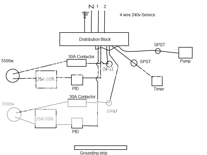
3 Keg system, 240v supply. 1 pump (Leaning toward the LG over the 809)

The elements will be 5500W extra low density elements. They will be controlled by two Aubern PIDs. First question:

Auberins suggested either

http://www.auberins.com/index.php?main_page=product_info&cPath=1&products_id=3

or

http://www.auberins.com/index.php?main_page=product_info&cPath=1&products_id=106

I don't understand the different specs enough to make an informed decision. They both look like they do the same thing.

They suggested the RTD probe for better accuracy. Sounds good to me, plus it looks easier to install. I notice most use the K thermocouple it comes with. Is the nicer probe not worth the $20 to most people?

The current I will draw at 100% is about 23A. Is it worth the extra few dollars to get the 40A ssr and 40A heat sink or will 25A cause me no grief?

MAJOR CONFUSION INCOMING

Here is where I really get screwed up. Looking at some conversation and wiring diagrams the PID and SSR only control one of my hot legs to the element. Is that accurate? Does that mean I need two SSR for each PID so I can shut the element off completely? Or is that why people get the Double Pole Single Throw toggle switch? How could you turn off the element but still have the PID on so a temperature can be read?

Luckily, a coworker's dad is an electrician that is going to help me assemble the box. I just need to figure out what to buy to get me to what I want.

What I want is 2 PID's that control the two 5500w elements. A digital hardwired timer (The $30 from Auberins). The PID/Timer need to stay on regardless of the elements being on. Toggle switches for each element and for a 120v pump. Indicator lights letting me know which element or pump is on. Maybe another 120v switch and indicator for a stirrer.

Any recommendations for switches or lights would be awesome. I want to stay away from rocker switches with the LED indicator in them.

This makes me want to take a college class on electronics as this seems to be over my head.
 
Hey J,
The first of the two PIDs is slightly more advanced, supports more probes and they say the PID logic is a bit more advances. Either one will do fine.

RTD probes are the way to go, I suggest the 1/4" NPT ones with disconnects. Pick up some 1/4" jam nuts and silicone O rings from bargain fittings and you're in bitness.


I run my 5500W element with a 25A SSR. Depends on the quality of the SSR I suppose. The crucial item is the heat sink.

You COULD use one SSR to switch off one side of the element, when it is disconnected the side still connected has no place for current to flow. So in essence it is off.
However, using a contactor or BMF SPDT switch is a better practice. This way you know for sure the element is completely de-energized. Also, when SSRs fail they can fail closed, so the element/circuit could get stuck in the on position.

If you want something more industrial controls-ish, check out the plastic 22mm panel switches and indicators at automationdirect.com or factorymation.com. They're probably a little different than what you're used to working with but I think they are ideal. In my sig there is a build thread and an electrical primer, if you haven't read them already the primer may help your understanding. You can see the switches and indicators in the build thread.
 
Thanks CodeRage for the reply. No current flow / element off makes sense, but I think I will do the better practice and use a SPDT. To be able to read the temps I would have to leave the SPDT ON until my brew day is complete and then turn it off....correct? Also I need a DPST switch rated for 240v 25A (I think), anyone have any good links to some?

I will buy the 25A SSR and 25A Heatsink from Auberins, I assume these are good quality.

I saw the 1/4" RTD probe but don't remember seeing one with disconnects, will have to look that up again.

I will check out those links for the controls, thanks! I have read your primer and build but will re-read as I have a slightly better grasp of what I want now.
 
Those illuminated push button switches look killer, but none of them seem capable of breaking 23amps =/

"24 volts AC at 10 amps
130 volts AC at 6.5 amps"
 
use a contactor to switch the heavy current, and a lighter-duty switch to switch the contactor on an off....
 
I saw the 1/4" RTD probe but don't remember seeing one with disconnects, will have to look that up again.

The disconnect is a separate item - You have to solder it to the probe wires, and mount the connector in your panel.

They are very nice, and very cheap. I highly recommend them.

Other options include "XLR" connectors or 1/4" stereo plugs/jacks. Both are more expensive than the Auber disconnect, though...
 
Here are one of the probes I was talking about. The disconnect is right on the probe. When you install it you don't have to worry about twisting the bejezous out of the pig tail. When you go to move your kettles for dumping and what not you don't have a pig tail dragging around behind the kettle either :)

J_Jones, marzit has it right. Auber has some 25 and 40A contactors. They are like really big ass'ed relays. When I flip an elements switch into the auto position, the switch energized the contactor, sending power to one side of the element and the PID's SSR. The PID's SSR switches the element on and off as needed. When the element's switch is placed into Hand (Manual On) a second contactor provides power to both sides of the element, bypassing the PID SSR. The cool thing about those switches are you can stack on all the contacts you need for one switch. They aren't designed for high current but are meant for control logic. You then use the control logic voltage to turn on relays, contactors, SSRs, etc etc to handle the high current stuff.
 
The disconnect is a separate item - You have to solder it to the probe wires, and mount the connector in your panel.

They are very nice, and very cheap. I highly recommend them.

Other options include "XLR" connectors or 1/4" stereo plugs/jacks. Both are more expensive than the Auber disconnect, though...

First option sounds great. I like the idea of being able to remove them easily. Then I can quick disconnect off the panel and unscrew from kettle as necessary. Cool :)
 
Here are one of the probes I was talking about. The disconnect is right on the probe. When you install it you don't have to worry about twisting the bejezous out of the pig tail. When you go to move your kettles for dumping and what not you don't have a pig tail dragging around behind the kettle either :)

J_Jones, marzit has it right. Auber has some 25 and 40A contactors. They are like really big ass'ed relays. When I flip an elements switch into the auto position, the switch energized the contactor, sending power to one side of the element and the PID's SSR. The PID's SSR switches the element on and off as needed. When the element's switch is placed into Hand (Manual On) a second contactor provides power to both sides of the element, bypassing the PID SSR. The cool thing about those switches are you can stack on all the contacts you need for one switch. They aren't designed for high current but are meant for control logic. You then use the control logic voltage to turn on relays, contactors, SSRs, etc etc to handle the high current stuff.

Thanks CodeRage and Marzit for helping me understand this. I figured I had to be missing something because the 25A switches are incredibly hard to find.

I could not find the Aubern 25A contacter but found this.

http://www.auberins.com/index.php?main_page=product_info&cPath=2&products_id=129&zenid=adb68c15a211317bcd51f67f5d49f670

I would need two of those per PID/Element/SSR if I wanted to have an element kill switch and bypass, or one per element if I just wanted an element kill switch. Correct? CodeRage why would you want to bypass the PID and turn on the element?
 
There are a couple of ways to do it, but the way I suggest to do it is probably the most redundant. So you would need 2 contactors to do it. The nice thing is they are much cheaper than SSRs. They just aren't designed for fast switching. That 30A will work fine.

If you just wanted an Off/Auto switch, yes you would only need 1.

Though not likely, a PID controller or SSR could crap out on you in a brew session. I do this kind of stuff for work so I am used to putting a manual override control in. So I am more comfortable having a manual override handy. Say you went to a Brewtroller, BCS or something else eventually. Should something go awry in the automation, you can still run the process in Hand (Manually). So think of the PID controller as a miniature automation device, which it is.
 
Here is a rough diagram. Just pretend like I have everything properly grounded :)

Circuit.jpg


Paint kicked my butt for trying to make it look good but hopefully you will get an idea of what I am after.

Where in here would I put fuses and indicator lights?

Please critique, I have no idea what I am doing :p
 
Wondering if I should skip the RTD probe for the BK and just use the Type K that comes with. Not like it needs to be that accurate right?
 
I have been using THESE for both of my elements without any problems.

On the BK you will need the PID to do a duty cycle. I set mine around 60% for 5-8 gallon boils. This past weekend I boiled down from 7.25g to 5.25g in 90 mins at 60%
 
J_jones. The one's it comes with aren't water tight. I think Bobby M got them to work by jb welding the threaded collar onto the probe. So that's an option if you are comfortable using JB weld.

Ranger, those will most certainly work. I'm not being critical but, I don't like using the spade type connectors or metal switches around control panels. Some times those spades loose their grip if the panel is open and closed a bunch. I would hate for one to come loose and make contact with the control panel. Design wise, it's best to keep high current stuff away from the control panel.


J Jones, in your drawing both L1 and L2 should go through the contactor (they're SPDT), through the SSR, and then to the element.
The boil off rate for 5500W in a 5gal batch is amazing isn't it?
 
I have been using THESE for both of my elements without any problems.

On the BK you will need the PID to do a duty cycle. I set mine around 60% for 5-8 gallon boils. This past weekend I boiled down from 7.25g to 5.25g in 90 mins at 60%

That switch is only rated for 10amps at 250v. You have no problem breaking a 5500w 240v element with it? Or are you using something else to break/make the current?
 
J_jones. The one's it comes with aren't water tight. I think Bobby M got them to work by jb welding the threaded collar onto the probe. So that's an option if you are comfortable using JB weld.


J Jones, in your drawing both L1 and L2 should go through the contactor (they're SPDT), through the SSR, and then to the element.
The boil off rate for 5500W in a 5gal batch is amazing isn't it?

There is a free one that comes with the PID right? I might as well try it. I thought the PID/SSR would handle one of the legs and the SPST/Contactor would handle the other leg. Is that not how most people do it? I was just thinking it might be nice to not kill the PID power because I might like to look at the temp, even with the element off. Like when I am chilling with my IC in the BK.
 
The PID will still have power, what you are doing is cutting the potential from both L1 and L2 loose from the element. The PID gets it's own power else where, before the contactor. if you only cut one side with the contactor and the PID turns the SSR on it will energize one side of the element even though it is off. You'll still get a temp readout.
 
The PID will still have power, what you are doing is cutting the potential from both L1 and L2 loose from the element. The PID gets it's own power else where, before the contactor. if you only cut one side with the contactor and the PID turns the SSR on it will energize one side of the element even though it is off. You'll still get a temp readout.

That makes sense CodeRage, would I need L1 and L2 to go to a DPDT then the contactor then?
 
That switch is only rated for 10amps at 250v. You have no problem breaking a 5500w 240v element with it? Or are you using something else to break/make the current?

You are right I just looked at it quickly this morning. THIS is the actual switch I got.
 
You are right I just looked at it quickly this morning. THIS is the actual switch I got.

Wow, super cheap

That would eliminate the need for the 30a contactor, but it seems like it would not hold up as well. I am wary of ebay stuff... it's like getting things from walmart in my experience.. 8/10 times it is cheapo cost cutting junk. For the price and simplicity though I might give it a shot and go for the contactor setup if they fail.

EDIT $11 for shipping damn!
 
I purchased 6 of them:

2 for - elements
1 for - BCS-460
3 for - misc. 110v outlets, for pumps rights now

They have held up just fine with no problems. I have probably 10 brews with the new system. The switch has a screw down terminal, so I got the crimp ring terminals for my wires and soldered the wires to the ring terminal first and then attached it to the switch. I also taped every connection with elec. tape. It was a little time consuming but it seems to be working just fine.
 
The DPDT? the Off/Auto switch?

No, L1/L2 goes straight to the contactor's contacts.
You'll use the Off/Auto switch to energize the coil on the contactor, which will close the contacts energizing the element circuit.
 

Latest posts

Back
Top