The cold sucks, going electric

Homebrew Talk - Beer, Wine, Mead, & Cider Brewing Discussion Forum

Help Support Homebrew Talk - Beer, Wine, Mead, & Cider Brewing Discussion Forum:

This site may earn a commission from merchant affiliate links, including eBay, Amazon, and others.

snail

Well-Known Member
Joined
Jul 9, 2008
Messages
321
Reaction score
14
After brewing during a snowstorm, I've decided electric brewing in the comfort of my kitchen is the only way to brew during the winter.

My main breaker panel now has a 40a GFCI breaker feeding the range receptacle in my kitchen.

This is the start to my wiring diagram, hacked from kal's diagram.

The 30a supplementary breaker is so I can use NEMA L6-30 plugs and receptacles for the 5500W element.

Can you guys critique this and give suggestions?

systemc.jpg
 
I'll start the ball rolling, by pleading confusion. So- you plan to unplug your range and plug in the 240V / 5500W heatstick / element fitted to boil pot? What are the power key switch and relay doing? And you didn't illustrate the 40A GFCI breaker, which would be off the black & red leads to the bottom?
 
I plan on using the range receptacle to power my control panel. Sorry I forgot to change the power key switch. This diagram is just to supply power to the control panel, haven't added the element or anything yet.
41993923.jpg
 
So your intention for the 120v power light is just to let you know that 120v power exists, right?
 
No, that's power to the contactor...which supplies 220v.

I think following Kal's awesome example is a great place to start. I'm doing the same thing....just leaving out the ammeter and voltmeter/dc power supplies. Otherwise my box (toolbox) is pretty close.

What kind of system are you using? How many vessels/elements/PID's? With that info we can go further.

Is your on switch not rated for 120? If you're using the right size wire, you MAY not need that fuse. I wouldn't discourage you, but Kal only seemed to use fuses to protect the real small wires and sensitive PID's. But I could be wrong; I would let him weigh in on that.
 
Ok I found Tiber_brews build thread and think this will work better for what I want to do. So I'm switching up diagrams.

ScubaSteve, my system as of now, is a 15gal Boilermaker, Coleman Extreme for mashtun. I've been heating up my water for the mash in the Boilermaker and mashing in. Then heat up the sparge water in the Boilermaker and drain the mashtun into a different pot that would then be transferred into the Boilermaker after sparging. I know, I need a bigger HLT.

I would like to do a RIMS or HERMS system sometime in the future.

I'm a lot more pleased with this diagram so could you please weigh in on this one instead? :cross:

30780756.jpg
 
Ok I found Tiber_brews build thread and think this will work better for what I want to do. So I'm switching up diagrams.

...
You did a good job modifying the diagram. That will certainly work for you as you have drawn it. Question - How large is the pot that you are using the 5500W element in? (And what is it being used for (HLT? Boil kettle?) Reason I'm asking is that a 5500W element is a lot of power even for a boil in a Sanke keg kettle.

Edit: It is not a problem, however, as the PID will control the temps and the boil rate. Reason (I guess) I'm asking is, what else does your plan call for in its final version. But - you can always change the element out later on. (He said - thinking out loud.)

BTW, I'd be glad to help you in diagramming your project out.
 
I saw that you were helping Tiber_brew throughout his design process, modifying the wiring diagram as he chose different parts. So thanks for unintentionally helping me too! :mug: I should have probably put your name as a source in the diagram. Credit should be given where it is deserved.

Anyway, the element will be in my 15 gal Boilermaker which is acting as a HLT and boil kettle. I have the 15 gal Boilermaker, and two 7.5 gal kettles (from when I did 5 gal batches). My process is heat mash water in Boilermaker, mash in, heat sparge water in Boilermaker, drain mash tun to 7.5 gal kettle, sparge from Boilermaker, drain mash tun to other 7.5 gal kettle, another sparge from Boilermaker, then transfer all wort from kettles and second sparge from mash tun to Boilermaker. Kinda a PITA, maybe santa will bring me a new HLT for xmas.
 
I saw that you were helping Tiber_brew throughout his design process, modifying the wiring diagram as he chose different parts. So thanks for unintentionally helping me too! :mug: I should have probably put your name as a source in the diagram. Credit should be given where it is deserved.
...
Please do not sweat that in any way. I pub the diagrams (in my style) to help others. Once that is done it becomes "public domain" .. So be it. I'm really pleased that it helped you (and others) in the understanding of how "stuff works".

Think your process through and I'd be more than pleased to help you in any way that I can. You are doing great so far. Please keep it going. After all, it's all about designing a system that is easy to use and something that will give you consistent and reliable results. Brewing great beer is not about formulas. It's all about consistent processes that can be tweaked.

I'm pleased that you are thinking this through. You are doing great so far. Please keep going and let me know if I can help in any way.

Prost!
 
So I was reading through the build thread again and read that the bus bars need to be rated for the input wire size. So in my application I would be using 50amp or 6ga blocks? What size do the neutral and ground need to be?

Also, line 1 & 2 coming out of the blocks needs to be 6 ga wire, correct? Once past the breaker, I would size the wire appropriately to the breaker?
 
Snail,

Missed your PM, so far the diagram looks good I think. You will need 50A bus bars using that 50A appliance cord. Also, since you eliminated the 30A breaker before your power circuit you'll need to run a 50A contactor for that, and 6 ga wires to your breakers.

If you do add a new HLT and go HERMS or switch to a RIMS setup you'll end up with 2 elements. If this is the case, you might consider using DIN mountable contact blocks, as they offer a lot of expandability (as long as your enclosure is big enough). If you're interested I've got a lot of DIN rail and several contact blocks, caps, and end clamps left over from my build that I'll be looking to get rid of for basically nothing. I can't return them and they're just taking up space right now. If you wired through these after the SSR you could later switch out your element switch for a 3 pos selector, add a second coil, and wire that to a second receptacle for the new element, allowing you to control either element with the PID SSR you've already got.

The indicator light on your first contactor is wired across the two hot legs. If you do it this will have to be a 240V light. Same with the indicator that's wired on the element contactor. Also, these will have to wired in with 6 ga and 10 ga wire respectively. You could switch them to be wired in parallel with the contators' coils, allowing you to use 120V lights and 14 ga wire, but then they are only indicating whether or not the coils are powered, not whether there is power through the contactors' terminals.

Another thing to consider is that your pump, if you're using a March or Chugger, will be drawing a lot less than 15A, and the PID and contactos less than 0.5A. You could definitely switch the 15A breaker for a 2 or 3A D curve and have plenty of room to spare. Similarly, the 1A fast blow fuse on the PID isn't really going to do much. The PID uses 5 W. At 120V that's less than 50 mA. If the thing ever draws enough power to pop the 1A fuse it's toast and something's really wrong. You could switch that out for a 0.1 A, or just ditch it all together.
 
Also, I didn't see it mentioned anywhere but you might consider adding an estop circuit and going to a momentary PB power on setup. That way in case of a power failure you're system won't start back up as soon as the power comes back on, and you've got the big red "OH POOP!" button in case of emergency. It wouldn't cost much more, all you'd need is an extra low current fuse, the e-stop PB, and replace the key switch with a momentary PB. You can wire up your current contactor to latch when the power on button is pushed and drop out when the estop is slapped. It's pretty simple and adds a layer of protection.

Edit: If you really want the key switch you can get a NO spring return key switch for the power on portion, having that latch the relay, then include the estop.
 
You better double-check that breaker for the range receptacle. Those are not normally GFCI breakers. I would be very surprised to learn that is GFCI.
 
I took out the original 40 amp breaker, and replaced it with a 40 amp GFCI breaker.
140.jpg

Ridiculous how much those things cost. Too bad my panel wasn't a GE otherwise I would've bought a spa panel and used that breaker.
 
Snail,

Missed your PM, so far the diagram looks good I think. You will need 50A bus bars using that 50A appliance cord. Also, since you eliminated the 30A breaker before your power circuit you'll need to run a 50A contactor for that, and 6 ga wires to your breakers.

If you do add a new HLT and go HERMS or switch to a RIMS setup you'll end up with 2 elements. If this is the case, you might consider using DIN mountable contact blocks, as they offer a lot of expandability (as long as your enclosure is big enough). If you're interested I've got a lot of DIN rail and several contact blocks, caps, and end clamps left over from my build that I'll be looking to get rid of for basically nothing. I can't return them and they're just taking up space right now. If you wired through these after the SSR you could later switch out your element switch for a 3 pos selector, add a second coil, and wire that to a second receptacle for the new element, allowing you to control either element with the PID SSR you've already got.

The indicator light on your first contactor is wired across the two hot legs. If you do it this will have to be a 240V light. Same with the indicator that's wired on the element contactor. Also, these will have to wired in with 6 ga and 10 ga wire respectively. You could switch them to be wired in parallel with the contators' coils, allowing you to use 120V lights and 14 ga wire, but then they are only indicating whether or not the coils are powered, not whether there is power through the contactors' terminals.

Another thing to consider is that your pump, if you're using a March or Chugger, will be drawing a lot less than 15A, and the PID and contactos less than 0.5A. You could definitely switch the 15A breaker for a 2 or 3A D curve and have plenty of room to spare. Similarly, the 1A fast blow fuse on the PID isn't really going to do much. The PID uses 5 W. At 120V that's less than 50 mA. If the thing ever draws enough power to pop the 1A fuse it's toast and something's really wrong. You could switch that out for a 0.1 A, or just ditch it all together.

Trigger,

So I found some 50 amp bus bars that should work.

Do you think I would be better off finding a 50a contactor or putting a 30a breaker before the contactor for the main power?

What is the difference between the B, C, D supplementary breakers? Good point on the 15 amp breaker, I should downsize it.

How would you wire up the momentary push button? Wouldn't the switch that I have for the main power work as a e-stop?
 
The 50A contactor I got from ebay cost about $44, it's a ST3P. You can get a 40A from Auber that's STDP for $18. I originally went with the 50A as an "in case" thing, as there's a 50A circuit that I might be brewing on in the future. I was planning on retaining the ability to run both elements at the same time with a bit of rewiring. If you don't see yourself ever switching to a 50A circuit then I would go with the 30 or 40 A from Auber and add a 30 or 40 A breaker before it. One thing to keep in mind with this is that you will only be controlling the two hot legs, the neutral won't be switched by the contactor. Lots of guys here run like that, but it's a decision you should think through yourself (2P or 3P main power contactor).

The B, C, or D refers to a combination of overcurrent and time, but basically, the B curve will trip fastest on a smaller overcurrent, where the D curve will trip slowest on a larger overcurrent. For inductive loads (pump motors in our case) you want to go with a D curve, for resistive loads (PID's, lights and such) you want a B curve. For the elements I went with C curve, but really probably should have been B curve since these are straight resistive loads.

For the momentary PB you would take power through a small fuse at the incoming terminal of your power contactor, wire that through the PB, then to the line in side of the coil. Then you would run power from the protected side of the breaker powering your PID, through your estop, and again to the line in side of the coil. The way it works is when the PB is pressed the coil is energized, closing the contacts and providing power to your breakers. Now that the breakers are powered, the branch running through your estop is providing power to the main contactor's coil, keeping the contactor latched, even after you release the momentary PB. To shut the system down you hit the estop. This breaks the connection and drops power to the contactor's coil, opening it's contacts, and shutting power off to the entire system. Similarly, if the system was powered up and the cord gets unplugged or the power goes out, the contactor drops out, so the system will not start up again until power is restored AND you hit the momentary PB. If you want to retain the key lock, get a spring return one and wire it in instead of the momentary PB.

The switch that you have could function as a system off, but an estop is a big red or yellow mushroom style PB. In a true emergency it is a lot easier to slap a 40mm mushroom PB than to reach over and turn a key. Also, I highly suggest you go with a twist release or even a key release for this. They take a conscious effort to reset, whereas a simple push/pull is easier to accidentally reset. The idea behind using an estop is that it takes no significant thought or motor skills to shut the system off in an emergency.

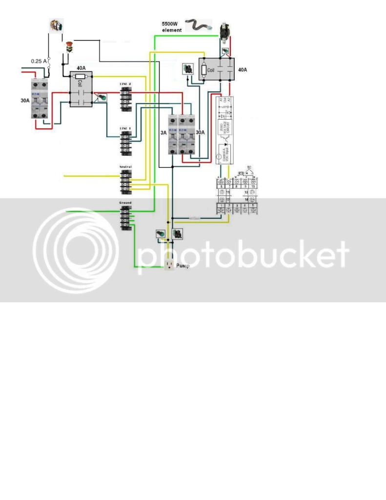
If this helps check out my wiring diagram here. The estop and power on circuits are shown in the upper left. You can ignore the RIMS/off/BK and Pump switches if you don't want to include them. They are simply additional NC contact blocks wired onto those particular switches so that the system cannot be turned on when power is provided to either element or the pump. If you want to include these too, check out Kal's page on the safe start interlock at the electric brewery.com. I got the idea for my safe start interlock from him, so all credit belongs there.
 
Sorry, one error above. You should tie the power in PB into the circuit BEFORE the estop. That whey when the estop is pressed the PB will not function. If you tie it in at the coil as I said before you could power up the system by pressing the power on button even when the estop was hit. The relay wouldn't latch, so it would only be powered as long as the power button was being held, but this would still be contrary to the purpose of the estop.
 
Here is a newer diagram. Just added the 30A breaker right in the beginning. Here is the momentary pushbutton I'm looking at. This is the estop. Would you be able to help me add these to the diagram? I understand how they work I'm just not sure how to go about wiring them.

16834966.jpg
 
Here is a newer diagram. Just added the 30A breaker right in the beginning. Here is the momentary pushbutton I'm looking at. This is the estop. Would you be able to help me add these to the diagram? I understand how they work I'm just not sure how to go about wiring them.

Here's what I was talking about with the PB and estop. If anyone sees a problem please weigh in.

snailwiring.png


On my system I used a 3PST main power contactor, and that is switching the neutral line so I was able to connect both the start and latching part of the circuit through a single contact block on the estop. If you go with a DPST contactor, as you have diagramed, then you will need to use 2NC contact blocks on your estop. Have the start button wired to one of the contact blocks and the power coming from your 3 A breaker coming into the other contact block. Jump the other side of the contact blocks together and into your power contactor's coil. This will have your estop functioning as a total system shutdown, as it should. If you do not use two contact blocks and instead tie both lines through a single contact block you could power the 3A circuit by pushing your start button even while the estop was triggered, which wouldn't be what you want.
 
I just noticed that the indicators for your element and main power contactor are both wired for 240 V. You can do this, just make sure that you get 240 V lights and that you run 10 ga wire for them. Another way of doing things would be to wire the elements in parallel to the two contactors' coils. They won't tell you if the contactor is actually providing power, but they will let you know when the coil is energized. You could wire either of the main power contactor's outputs through the light to neutral for a 120 V light and the non-SSR side of the element contactor's output to the light and then to neautral. Again, this will only tell you if that one leg is powered, but it would allow you to use 120 V lamps.
 
Automation direct sells what appear to be good quality switches and the shipping is more reasonable than the ebay switches you listed above. I have had good luck with idec switches which are industrial quality. You can buy them at reasonable prices on ebay if you are not in a hurry. I have bought both new and used switches and been happy with both. Search "idec switches". You can also specify pushbutton or selector or e stop.
 
After the 3A breaker, the circuit where all the switches and pump are, what wire gauge would I use? I'm assuming I can go pretty small, but how small?
 
After the 3A breaker, the circuit where all the switches and pump are, what wire gauge would I use? I'm assuming I can go pretty small, but how small?

Its okay to use a larger gauge wire than the circuit is rated for. 14 AWG (Good for 15A) will probably be the smallest control wire you will find readily available.
 
Trigger,

So I found some 50 amp bus bars that should work.

Do you think I would be better off finding a 50a contactor or putting a 30a breaker before the contactor for the main power?

What is the difference between the B, C, D supplementary breakers? Good point on the 15 amp breaker, I should downsize it.

How would you wire up the momentary push button? Wouldn't the switch that I have for the main power work as a e-stop?


Not to nitpick, but those are terminal blocks. Busbars work a little differently, where the line in powers all the lines that connect to the bar. It'd be like if you used a jumper across every terminal of the terminal block. Not sure it matters....
 
ScubaSteve, you're right! I think I'm going to switch to DIN contact blocks anyway though :cross:
 
Yeah, those are cool....I'm wishing I used those, because I'll be using DIN circuit breakers. But, I spent about $40 on bus bars...so I need to use 'em.
 
the ebay switches by electrical parts have crazy shipping prices, you get a much better deal going to their website - pioneerbreaker. They have great service. If you call, ask for Tamas. He help me with a bunch of stuff.
 
I noticed that too. I was looking at some parts on their ebay site and clicked on their contact us page. It listed tamas@pioneerbreaker as the contact. I googled pioneerbreaker and almost all of the parts I need have free shipping, when ebay is like 11 bucks.
 
Yeah, those are cool....I'm wishing I used those, because I'll be using DIN circuit breakers. But, I spent about $40 on bus bars...so I need to use 'em.

I'm using these bus bars and am extremely satisfied:

288201.jpg


DIN mount is great too, but I wouldn't fret over using bus bars. I suppose it comes down to your particular panel layout, and each will be different.

TB
 
Here's what I was talking about with the PB and estop. If anyone sees a problem please weigh in.

snailwiring.png


On my system I used a 3PST main power contactor, and that is switching the neutral line so I was able to connect both the start and latching part of the circuit through a single contact block on the estop. If you go with a DPST contactor, as you have diagramed, then you will need to use 2NC contact blocks on your estop. Have the start button wired to one of the contact blocks and the power coming from your 3 A breaker coming into the other contact block. Jump the other side of the contact blocks together and into your power contactor's coil. This will have your estop functioning as a total system shutdown, as it should. If you do not use two contact blocks and instead tie both lines through a single contact block you could power the 3A circuit by pushing your start button even while the estop was triggered, which wouldn't be what you want.

This may be a little late, but Trigger is right. The momentary pushbutton and e-stop seem to be wired wrong. As pictured, they only kill power to your elements and pumps. They should be in series and the output of the E-Stop should be the black wire that leads to the "main" contactor on the left. That way you'll need to have the momentary pushbutton engaged AND the E-Stop (actually a NC switch) should be engaged in order to have a power ON condition. If you push the pushbutton off, or hit the e-stop, it kills power to the main contactor and the ENTIRE system goes dead. What if something happens IN the box? You'l want to turn the entire thing off.
 
ScubaSteve,
I'm a little confused now. I thought I was good to go with the most recent diagram trigger revised. The way I'm reading it is you push the momentary switch, which only allows power to go through it until you let go. That allows power to go through the main contactor. Power will go through the 3A breaker and back up to the emergency pushbutton, but because it's NC, it allows power to keep going through the contactors coil, therefore still powering the system. To turn the system off, you hit the emergency stop, which makes it NO, cutting power to the contactor, and the system.

I hope it's not wrong. I bought all the switches and stuff for it already.
 
Scuba, I could be wrong here, but I think that you're mistaking the momentary PB on a latching relay for a mantained PB. I drew that diagram based on my own system, which uses the same setup. The intention was to create a system that will not power on until the power button is punched any time it loses power. Also, whenever the power relay drops out there is no power available to the system anywhere except to the power on PB. Until the e-stop is reset the power on PB will not function, provided it is wired through a separate NC contact block on the e-stop.
 
As I read that diagram, if you hit the e-stop, the current to the entire control panel is shut off at the contactor. The momentary push button starts the control panel by closing the contactor. However, if the e-stop is hit, the contactor won't close until the e-stop is reset. In my simple mind, it all seems to work. Nicely done!
My system is more complex in that I used another small relay for the start/e-stop circuit.
 
Scuba, I could be wrong here, but I think that you're mistaking the momentary PB on a latching relay for a mantained PB. I drew that diagram based on my own system, which uses the same setup. The intention was to create a system that will not power on until the power button is punched any time it loses power. Also, whenever the power relay drops out there is no power available to the system anywhere except to the power on PB. Until the e-stop is reset the power on PB will not function, provided it is wired through a separate NC contact block on the e-stop.

Yep Trigger, I got two NC contact blocks for the emergency push button. Should be good to go! :mug:
 
Nope...you guys are right. I was smoking crack when I wrote that. I see it now! It's a nice design....I wonder if I can do that in my build now...hmmmm.....:)
 
Sorry, but that drawing makes no sense to me.

The E-stop button should have one side landed to the fuse, and the other side landed to one side of the start push button. The other side of the push button should be wired to the coil. The other side of the coil should be wired to neutral.

The the black wire coming through the contactors contact going to the lamp needs to be tied to the coil the same spot the push button is landed.

Be careful not to cross legs here or you will make a dead short.
 
I see what you did, but the problem with that is you can energize the system by holding or pressing the start button even if the e-stop is engaged.
 
Back
Top