I need a wiring diagram for a single PID controlling a single 240v heating element. I've been surfing the Internet and have found some that are almost what I need, but not quite. Any help would be appreciated, thanks.
You are using an out of date browser. It may not display this or other websites correctly.
You should upgrade or use an alternative browser.
You should upgrade or use an alternative browser.
I need a single PID, single element diagram
- Thread starter GRHunter
- Start date

Help Support Homebrew Talk - Beer, Wine, Mead, & Cider Brewing Discussion Forum:
This site may earn a commission from merchant affiliate
links, including eBay, Amazon, and others.
Tell me what you want and I'll draw it for you.I need a wiring diagram for a single PID controlling a single 240v heating element. I've been surfing the Internet and have found some that are almost what I need, but not quite. Any help would be appreciated, thanks.
I've posted a few diagrams here. Perhaps one of 'em might be close?
P-J
OP
OP
GRHunter
Well-Known Member
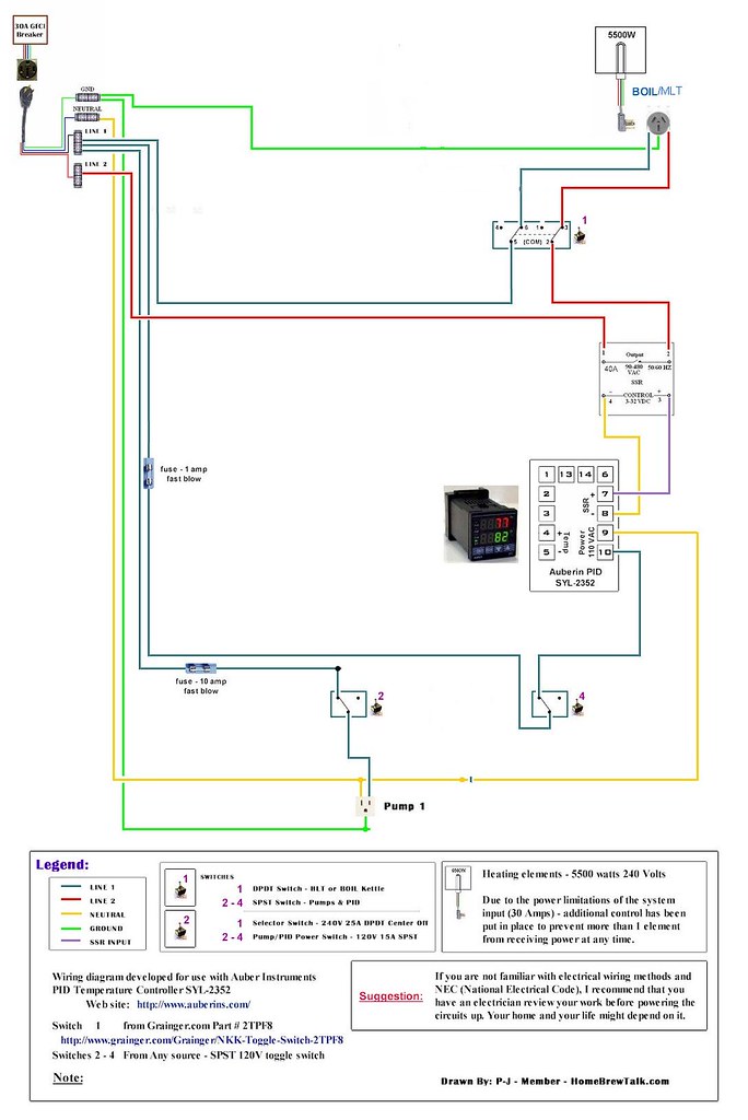
I need a wiring diagram for a system with just a single PID (Auber SYL-2352) controlling a single 240 volt 5500 watt heating element (Camco #02963 ultra low watt density RIPP element). Initially I just want a very basic setup. It will be a single kettle that I will use as both my HLT and BK. So just the ability to heat my strike water and to boil my wort. If you can dig up a diagram that would be great, thanks.
Tell me what you want and I'll draw it for you.
I've posted a few diagrams here. Perhaps one of 'em might be close?
P-J
I suggest that you use this diagram:Auberin-wiring1-a4-5500w-30c.jpg
It is setup for a HLT and Boil kettle. You can use it as is - but - just don't set up the HLT outlet and its wiring from the DPDT switch. I suggest that you use the switch in any case as it will provide a positive disconnect for the heating element and if you add a HLT later on, you don't have to replace the switch.
BTW: The whole setup will fit in the Auberins Project Box
Please let me know if this is ok or if you want something added/changed.
OP
OP
GRHunter
Well-Known Member
Does this whole setup fit in the Project Box? If it does, it might actually be better than what I was looking for. I just want one PID and one element working initially, but I would like to move in to a dual element design with pumps as the next step.
I suggest that you use this diagram:Auberin-wiring1-a4-5500w-30c.jpg
It is setup for a HLT and Boil kettle. You can use it as is - but - just don't set up the HLT outlet and its wiring from the DPDT switch. I suggest that you use the switch in any case as it will provide a positive disconnect for the heating element and if you add a HLT later on, you don't have to replace the switch.
BTW: The whole setup will fit in the Auberins Project Box
Please let me know if this is ok or if you want something added/changed.
Does this whole setup fit in the Project Box? If it does, it might actually be better than what I was looking for. I just want one PID and one element working initially, but I would like to move in to a dual element design with pumps as the next step.
I believe it will fit as long as you are using a single PID.
wilceaser
Well-Known Member
PJ would it possible to run a temp prob just for the HLT?
The HLT is the place where you would want to control the temperature so it's where the probe would normally go. No need for one in the boil kettle.PJ would it possible to run a temp prob just for the HLT?
These are pretty close to what I was hoping to get done as well.
I am wanting a schematic for a BIAB system (much like what you are asking for, I believe, GRHunter). The MLT/and Boil Kettle would be the same vessel, thus a single element and PID. Only thing missing on the schematics you posted, P-J is the wiring of the temp probe.
Do you have something like that worked up?
Cheers,
Jeff
I took some liberties with your diagram P/J in irfanview. Keep in mind that I am know very little about electrical, but I feel I know enough to merely delete stuff!
Would this be an acceptable set-up for a PID controlled BIAB setup?
Would this be an acceptable set-up for a PID controlled BIAB setup?
Temp probe wiring is really covered in the PID manual. With that said:...
Only thing missing on the schematics you posted, P-J is the wiring of the temp probe.
Do you have something like that worked up?

Setup for a RTD probe.

Setup for a type K probe.
I took some liberties with your diagram P/J in irfanview. Keep in mind that I am know very little about electrical, but I feel I know enough to merely delete stuff!
Would this be an acceptable set-up for a PID controlled BIAB setup?
That's fine. I see no problem in doing it that way.
What is the difference between the 2352 and the 2362 PIDs and which one is better? I am doing a 240V HLT and have 45A SSrs. Thanks
Either one will work. The difference? The SYL-2352 PID uses "fuzzy logic" for its temperature control which provides better accuracy. Take a look at the manuals for each one for a better understanding.What is the difference between the 2352 and the 2362 PIDs and which one is better? I am doing a 240V HLT and have 45A SSrs. Thanks
Another quick question (and sorry to Hi-jack GRHunter!):
What plugs are best?
I was thinking either NEMA L6-30, NEMA 10-30, or NEMA 14-40 without using the neutral (are any of these unacceptable?) from element to panel and then a standard 4 wire plug (ala The Electric Brewery) from panel (hardwired) to 240v 30am GFCI receptacle.
the NEMA 10-30 and 14-40 are likely the cheapest options. Are they kosher though.....
Mindar76
Member
Thanks for posting guys! I'm looking to do the same thing, a 5500k element, 240v, 30A, single pump, single PID, with dual temp probes (one for BK/HLT, one for MT) which all seems workable from some of PJ's diagrams (thanks, btw! Your work is astounding.) My only alteration is I want a secondary display to continually show the temp in the MT. I'll be using my old IC as the HERM coil, submerged in the BK/HLT, which will be controlled by the PID. In my head it's a simple on/of, PID display, secondary display, button for the element, button for the pump, big ol' E-stop button. Simple, sleek, small. Any suggestions?
Edit:
I've been looking at that diagram you linked to, P-J, for a while now. What I can figure for the element is simply eliminate the dual switch for the element in favor of a single switch, and cut out one of the pumps. That would take care of everything except the secondary display and the e-stop. What would you do to rig those into the existing diagrams?
Is this what you are looking for?I'm looking to do a 5500k element, 240v, 30A, single pump, single PID, with dual temp probes (one for BK/HLT, one for MT)
My only alteration is I want a secondary display to continually show the temp in the MT. I'll be using my old IC as the HERM coil, submerged in the BK/HLT, which will be controlled by the PID. In my head it's a simple on/of, PID display, secondary display, button for the element, button for the pump, big ol' E-stop button. Simple, sleek, small. Any suggestions?
I've been looking at that diagram you linked to, P-J, for a while now. What I can figure for the element is simply eliminate the dual switch for the element in favor of a single switch, and cut out one of the pumps. That would take care of everything except the secondary display and the e-stop.
Auberin-wiring1-a4-5500w-30d.jpg
BTW: That will all fit in the Auber Instruments Project Box. Place the SYL- 1512 under the cutout for the SYL-2352.
P-J
Mindar76
Member
You, sir. Are amazing.
jkarp
Well-Known Member
The HLT is the place where you would want to control the temperature so it's where the probe would normally go. No need for one in the boil kettle.
Though note the temp probe must remain connected to the PID - even when running in manual output mode for the boil.
jkarp
Well-Known Member
What is the difference between the 2352 and the 2362 PIDs and which one is better?
They have slightly different feature sets. You may want to read through the spec sheets and see which you like more.
2362 supports SSR and relay outputs, has a limit operating mode, and is closer to a "traditional" PID (though it does have a configurable AI).
2352 is SSR only, and has a more sophisticated AI. It also uses an entirely different value for P (not proportional band) so experienced PID users may find it a bit strange.
IMO, the 2352 is probably better for the "auto-tune and forget" crowd who don't want to learn (or mess with) PID operation. Folks more comfortable with PIDs will probably prefer the 2362 which is easier to tweak into a critically damped system (for mash temp control).
itrider
Active Member
I took some liberties with your diagram P/J in irfanview. Keep in mind that I am know very little about electrical, but I feel I know enough to merely delete stuff!
Would this be an acceptable set-up for a PID controlled BIAB setup?
jhollist, Do you have a higher resolution copy of this image? This is much closer to the design I am leaning towards; however, I will be using a 120v setup with 2000w element.
Thanks.
ColeBeer78
Well-Known Member
The only problem I have with that drawing. I would put the on/off switch for the heating element on the low voltage side of the SSR or control it with a contactor. I'm sure you don't want to be grabbing the 240v switch with the possibility of wet hands.
jkarp
Well-Known Member
The only problem I have with that drawing. I would put the on/off switch for the heating element on the low voltage side of the SSR or control it with a contactor. I'm sure you don't want to be grabbing the 240v switch with the possibility of wet hands.
Actually, you want the switch on the high voltage side because SSRs often fail closed. The PID is your low voltage side switch.
Think of it like a water shut off valve. The electrons flow thru the heating element but only when the valve is on. If the valve is off the electrons can not flow thru the heating element. If the element has two hot leads going to it I would assume it is designed for 220 or 460 volts. Turning off one leg prevents the flow of electrons from phase A to phase B. same thing if it is only 115 volt from phase A to neutral/ground.
jeffmeh
Well-Known Member
- Joined
- Feb 26, 2009
- Messages
- 2,145
- Reaction score
- 216
So it works because the system is A/C, and the other positive is required as a ground once every other cycle? Why can't the ground/neutral act as the ground when one of the hot leads is disconnected?
There is no neutral going to the heating element, it is H-H-G. If everything is operating normally, there is no current going to ground, as it is there for safety if something goes awry. So the 240V circuit is only closed (on) if both hots are powered. When the PID-controlled hot is not powered, there is no voltage going to the element (leakage aside). However, if you were to measure across the other element and ground you would get 120V.
I took some liberties with your diagram P/J in irfanview. Keep in mind that I am know very little about electrical, but I feel I know enough to merely delete stuff!
Would this be an acceptable set-up for a PID controlled BIAB setup?
Thank you for the help guys, I've spent some time reading about AC current trying to learn as much as I can.
So in the above schematic with a neutral and one hot 220v lead going to the PID, is the PID then powered by 110V (even though it does not have a second hot lead)? Could the PID alternatively be powered by two hot leads to 9 and 10?
jeffmeh
Well-Known Member
- Joined
- Feb 26, 2009
- Messages
- 2,145
- Reaction score
- 216
Thank you for the help guys, I've spent some time reading about AC current trying to learn as much as I can.
So in the above schematic with a neutral and one hot 220v lead going to the PID, is the PID then powered by 110V (even though it does not have a second hot lead)? Could the PID alternatively be powered by two hot leads to 9 and 10?
I believe so for the Auber 2352, which is quite useful if you only have 240V in the control panel. But if you also have 120V, I don't know of any good reason to use higher voltage to power the PID.
I believe so for the Auber 2352, which is quite useful if you only have 240V in the control panel. But if you also have 120V, I don't know of any good reason to use higher voltage to power the PID.
Yeah, I have a 3 wire 220v dryer outlet. And my understanding is that you need a 4 wire to split the 220v to 110v.
I also don't have a GFCI breaker on my dryer circuit. Does anyone know if GFCI can work with a three wire system installed in the project box?
There are some systems that have what's called a wild leg and it will measure 220v to ground. These set ups are rare and usually in commercial buildings. The heating element in this post is a 220v so you most likely will not hook up the neutral but to 2 phases. Both phases will be supplying 110v to either side of the heating element. You can turn the heating element off by installing the switch and breaking one leg. You will still have a measurement of 110 volts at the element but because the circuit is open it will not be heating.
gigapunk said:Thank you for the help guys, I've spent some time reading about AC current trying to learn as much as I can.
So in the above schematic with a neutral and one hot 220v lead going to the PID, is the PID then powered by 110V (even though it does not have a second hot lead)? Could the PID alternatively be powered by two hot leads to 9 and 10?
If the PID is designed for 110v it could hurt it to power it with 220v. The diagram that was provided above is great for what you are trying to do. It provides 220v to the heating element and 110v to the controller. If you follow the line diagram you should be ok.
vegoiltycoon
Member
- Joined
- Apr 25, 2013
- Messages
- 15
- Reaction score
- 0
I need a wiring too,please. I have 2 5500 watt heaters on 240.. I have two 1/2 hp pumps. These need to be controlled as two seperate pump and heater combos. I have 2 Sestos B2E timers and 2 Sestos D1S controllers.Timer 1 and controller 1 work together. Timer 1 will tell controller 1 when to shut down. It will also time a pump on simple on/off. I need an indicator light light between Timer 1 and pump. I need indicator light between Controller 1 and heater 1. Setup 2 is identical to Setup 1, mounted in same control panel. This is a biodiesel processor. Pump 1 and Heater 1 are on a 100 gal conical steel tank circulating from bottom to top. Pump 2 and Heater 2 are on a 55 gal drum circulating from bottom to top.
Sorry: Would like to help with a drawing - however - your build plan is based on Sestos components. I'm not familiar with them and it poses a sharp learning curve for me that I'm not willing to invest in.I need a wiring too,please. I have 2 5500 watt heaters on 240.. I have two 1/2 hp pumps. These need to be controlled as two seperate pump and heater combos. I have 2 Sestos B2E timers and 2 Sestos D1S controllers.Timer 1 and controller 1 work together. Timer 1 will tell controller 1 when to shut down. It will also time a pump on simple on/off. I need an indicator light light between Timer 1 and pump. I need indicator light between Controller 1 and heater 1. Setup 2 is identical to Setup 1, mounted in same control panel. This is a biodiesel processor. Pump 1 and Heater 1 are on a 100 gal conical steel tank circulating from bottom to top. Pump 2 and Heater 2 are on a 55 gal drum circulating from bottom to top.
Auber Instruments components - no problem..
Again, sorry...
vegoiltycoon said:I need a wiring too,please. I have 2 5500 watt heaters on 240.. I have two 1/2 hp pumps. These need to be controlled as two seperate pump and heater combos. I have 2 Sestos B2E timers and 2 Sestos D1S controllers.Timer 1 and controller 1 work together. Timer 1 will tell controller 1 when to shut down. It will also time a pump on simple on/off. I need an indicator light light between Timer 1 and pump. I need indicator light between Controller 1 and heater 1. Setup 2 is identical to Setup 1, mounted in same control panel. This is a biodiesel processor. Pump 1 and Heater 1 are on a 100 gal conical steel tank circulating from bottom to top. Pump 2 and Heater 2 are on a 55 gal drum circulating from bottom to top.
I have a sestos timer in my build so I'm familiar with that. I can answer questions if you have them. As for the other components, I am not so sure of since I used auber pids
jeffmeh
Well-Known Member
- Joined
- Feb 26, 2009
- Messages
- 2,145
- Reaction score
- 216
Sorry: Would like to help with a drawing - however - your build plan is based on Sestos components. I'm not familiar with them and it poses a sharp learning curve for me that I'm not willing to invest in.
Auber Instruments components - no problem..
Again, sorry...
P-J, I bet you have a drawing already with Auber PIDs and timers that would get him most of the way there.
")
P-J, I bet you have a drawing already with Auber PIDs and timers that would get him most of the way there.
Very true - however the differences between the Auber and the Sestos is huge. Very difficult to even try to interpret a chang in a plan.
jeffmeh
Well-Known Member
- Joined
- Feb 26, 2009
- Messages
- 2,145
- Reaction score
- 216
Very true - however the differences between the Auber and the Sestos is huge. Very difficult to even try to interpret a chang in a plan.
Understood. Just draw a cloud around each PID and timer and show the connections in and out of it, lol.
Incidentally, I'm kidding around, and don't expect you to draw anything you don't want to draw. You do enough around here already.
I cannot, for the love of God, understand why would anyone buy all this equipment without having a decent diagram on hand first...
Similar threads
- Replies
- 14
- Views
- 1K
- Replies
- 24
- Views
- 590
