Auberins pushbutton switches

Homebrew Talk - Beer, Wine, Mead, & Cider Brewing Discussion Forum

Help Support Homebrew Talk - Beer, Wine, Mead, & Cider Brewing Discussion Forum:

This site may earn a commission from merchant affiliate links, including eBay, Amazon, and others.

lukez

Well-Known Member
Joined
Jan 14, 2013
Messages
56
Reaction score
0
So I just realized I ordered the SW11 (1 NO 1 NC) switches instead of the SW1 (2 NO) from auberins and PJ uses the SW1 in his diagrams.
I tried looking up what the difference is and have a hard time understanding. I'm guessing I have to try and exchange these or can I use the 1NO 1NC that I have?
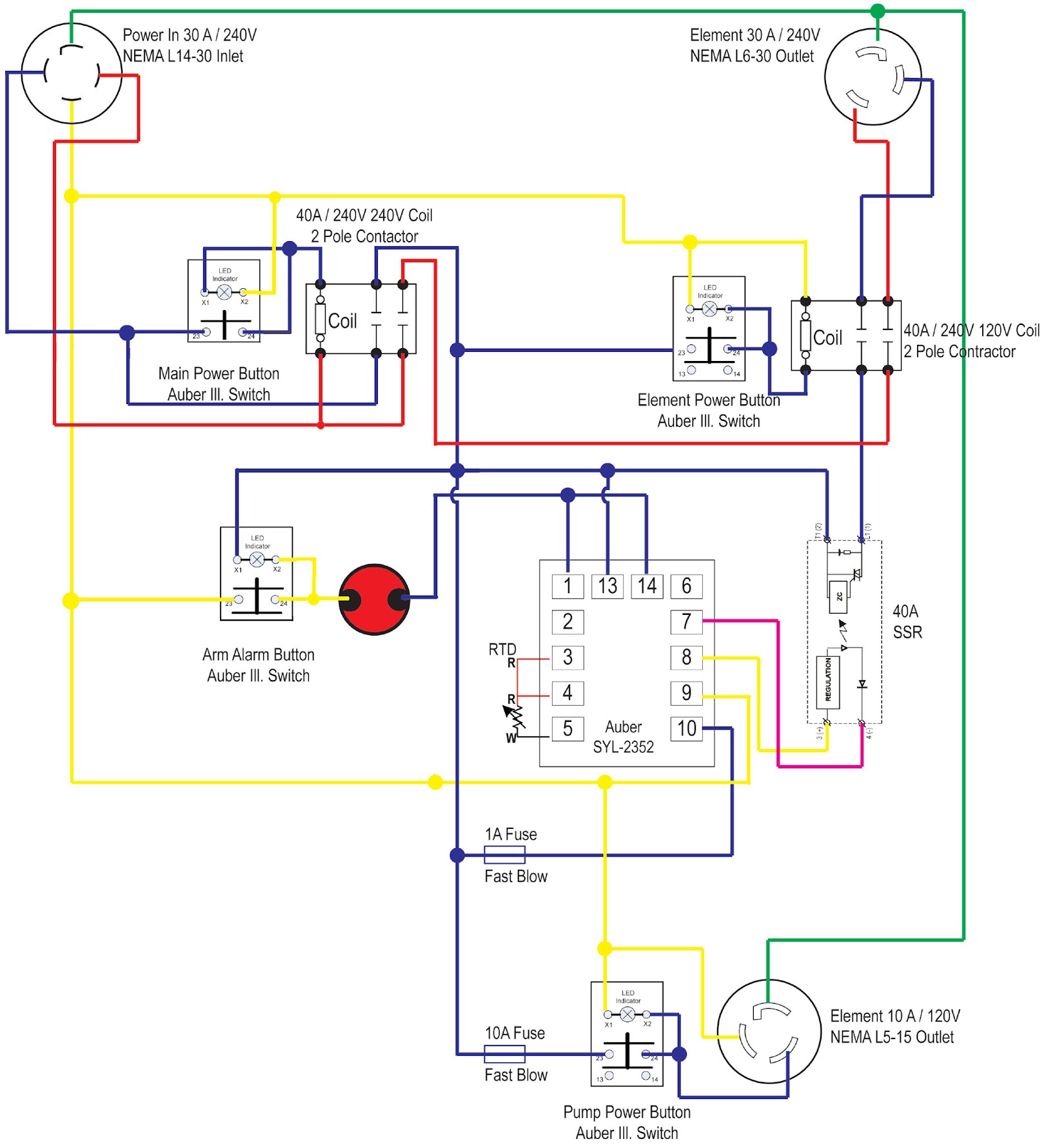
I'm doing this build here: https://www.homebrewtalk.com/f170/yet-another-ebiab-build-282235/
 
The main power switch is the only one in that wiring plan that needs to have 2 N/O modules in it. You can buy a module if need be.

If you already purchased the 240V coil contactor you are stuck with the original diagramed plan.
 
Looks like that diagram doesn't use the 2nd NO contact for anything. You should be fine, just don't wire anything to the NC contact.

EDIT: Didn't see PJ's reply and missed the power switch.
You could always just only switch 1 leg of the power for the contactor?
 
It's ok I rather do it the right way, I'll try to get module exchanged worst case I'll order another pushbutton oh well price you pay for exploring new territories!
Thanks guys
 
The main power switch is the only one in that wiring plan that needs to have 2 N/O modules in it. You can buy a module if need be.

If you already purchased the 240V coil contactor you are stuck with the original diagramed plan.

Why does the main power need 2 NO? why switch both hots if it is only for control of the main power contactor (which does need to switch both hots).
I see only one switch, as wire in the schematic in the 1st post, as needing 2NO - the alarm so that the button can be illuminated to show the alarm is "active".
This could be done with 1 NO if the switch is moved to switch the common into the PID (13).
 
If the only thing you have that needs 2NO is the main power switch, I'd just switch one of the hot legs. Your SSR does it to control the element, why not have your main power switch do it? One hot leg goes through the switch and then to the coil, the other hot leg goes directly to the coil. You've got a functional power switch and you don't need to contact Auber and get an exchange / buy another NO contact.
 
As mattd2 said, you could just wire one of the hot legs to the coil (in this case the black wire would probably be best) and then switch the other hot leg on the main power switch and you would be fine.

The only button that is going to be an issue is the alarm button. Because the circuit that is switched when you close the alarm button is not completed until the PID closes the relay when an alarm condition is reached, which means the button will not illuminate until the alarm is triggered.

I would recommend just buying another contact block for that switch and wire up the rest of the switches that you have. If you need an updated wiring diagram I can help.

Or move the alarm switch so that it provides power to the common alarm post (13) on the PID. Then a single NO block can be used to both light the illumination and provide power to the alarm.
 
so i can get away with using these switches??? volt or someone, would you be able to update the diagram to reflect these changes to clear it up for me?
 
This diagram should be correct:

wiring-diagram-lukez.jpg
 
So I finally got this thing powered up and it's not working properly. The 240 coil has incoming power (measured 120V for each hot leg).
There is no power coming out of the coil though.
The incoming red hot leg goes to one side of the coil. I have a black 14 gauge wire coming out of the black hot leg and going to the switch, #23.
Then #24 is jumped to X1 and X1 goes to the remaining side of the coil.

I measured voltage at #23 and it's 120V. At #24 it's 133V without the switch even being depressed???? When I depress switch both voltages drop to 110V.
So the coil is seeing 120v from the red wire and 133v from the switch without me even activating anything (which doesn't power the coil).

Is there something wrong with this wiring diagram or did I wire something wrong??

IMG_20130323_151252.jpg


IMG_20130323_151308.jpg


IMG_20130323_151322.jpg
 
I'm thinking the X1 and X2 wiring should be opposite of what I have, neutral to X1 and the hot coming for X2. Anyone agreed/disagree?
Also should the 240 coil relay have neutral where red wire is on the side to activate it? Or are both hot legs used to activate the coil relay?

Tried switching x1 and x2, no difference. Indicator always on, depressed or not.
Tried switching push buttons too, same result.

Tried putting neutral to one of the side connections on the coil relay instead of the hot (red) and it fixed the button issue but the relay doesn't work. Makes a buzzing noise when button is pressed and it gives no output.

I'm out of ideas, anyone can chime in?
 
a quick question, what is the voltage on your coil?

the main is 240V
Hmmmm...

There is a difference between the supplied voltage to the panel and the voltage delivered for the contactor pick coil.

Hmmm..

(I guess I really need to give up on this whole adventure of making custom diagrams and giving advice for everyone's benefit .. So be it.!)

Geeze....
 
Not sure what that means. But the red and black wires are measuring 120v each at the coil (at the lugs that secure the wires)
 
I get it 240 coil means you should deliver 120 to each side, not a neutral. Did I destroy it? :-(
 
I get it 240 coil means you should deliver 120 to each side, not a neutral. Did I destroy it? :-(
NO..!!!
You need to deliver 240V to the coil. NOT 120V to each side.

Just suppose that when you measure your 'voltage' it shows 120V on each of the 2 lines. However the lines are from the same phase? The actual pick voltage to the coil is then 0 volts.

Now what?

Set your meter to read 240 volts and measure the actual voltage delivered.!
 
I guess it does nothing...like it's doing!
So should I have 1 hot wire (red) going directly to the contactor pick and the other hot wire (black) going to the switch which then goes back to the contactor picks on the same side as the 120 that's already there, delivering 240 to one side of the pick? On the other contactor pick I should have neurtal.
Am I getting warm?
 
I guess it does nothing...like it's doing!
So should I have 1 hot wire (red) going directly to the contactor pick and the other hot wire (black) going to the switch which then goes back to the contactor picks on the same side as the 120 that's already there, delivering 240 to one side of the pick? On the other contactor pick I should have neutral.
Am I getting warm?
Suggestion... Call an electrician. You are in way over your head.

Please do not play "You Bet Your Life" - It is not worth it.
 
I agree with the others - you should probably contact an electrician. You are missing some of the fundamentals of electrical theory that could result in you damaging your panel, your house, or yourself. Here are some of the basiscs that P-J and others are trying to get at.

If you're running 240v in a 4 wire configuration, you should have Hot A, Hot B, Neutral, and Ground. Hot A and Hot B are both putting out 120v, neutral and ground do not provide any current and only carry it back (neutral under normal circumstances, ground in the event something goes horribly wrong). The important part to know though is that when measuring from Hot A to neutral your meter should read 120v. When measuring from Hot B to neutral you should again read 120v. Measuring A to B should give you 240v. But measuring A to A or B to B will give you 0v. You can easily be mislead into thinking you have 240v because you measure one terminal to neutral and see 120v, and measure another terminal to neutral and see 120v - but you could be measuring the same phase (A or B) and while it SEEMS like you've got 240v, you actually have nothing because it's the same leg.

-Kevin
 
Ya I understand those basics, I just don't know enough about relays to troubleshoot the issue so I reached out here. I thought that a 240 relay needed each hot to power it, and the original wiring diagram made sense and so does he second really, but it's not functioning properly so I started to second guess myself and these vague comments didn't help.
Anyway I sent back the switches to get the 2NO switches I needed in the first place. That should resolve my issue i just hope my relay is still good. We'll soon find out!

I think what you are missing is relay/contactors have 2 ratings - one for the contacts and one for the coil.
a relay with 240V contacts can have a multitude of coil voltages, e.g. 5V, 12V, 24V 120V or 240V.
What you need to check is what is written on your relays (and post here), should be something like contact rating and coil voltage.

Also going back to your post with the problem. can you remove all wires from the switch - except the black hot that comes from / goes to the contactor. Without having wired one of those switches myself it seems odd the way the nuetral(s) are connected to it.
 
If you followed the plan, the contactors called for are 40A/240V/120V which means they are rated to handle 40 amps and up to 240 volts on the input and output side - the 120v rating on the end is for the coil inside the relay. That coil is a simple electromagnet that, when energized, pulls the relay closed and supplies power from the input side to the output side. Being as it's 120v it requires a hot leg and a neutral leg.

SO - it comes down to what is on the contactor for the coil specification?
 
There is two relays, 240 for main and 120 for element. I tested the 120 and it's fine with a hot and neutral to the contactors. The 240 for main requires both got legs at the contactors I believe and that's where the issue was.
I can't trouble shoot now cuz I sent the switches back for exchange for the original plan.

Again what you are saying does not line up with the diagram. As far as terminology I understand that the "contacts"/"contactors" is the name for the points which are switched, and the "coil" is the name for the points which do the switching.
So do you have 2 relays -
Main power feed relay: 40A/240 contacts & 240V coil
element relay: 40A/240V contacts & 120V coil

To be sure of what you have/had done, can you confirm:
*For the main relay have you got Hot (line 1 - Red) on one side of the coil and Hot (line 2 - Black) on the other with the switch breaking one of the hot lines
*For the element relay have you got Hot (line 2 - Black) on one side of the coil and nuetral (white) on the other with the switch breaking the hot lines

Another thought is are you 100% sure you have contactors with 2 NO, and not a single pole contactor with 1 NO & 1 NC? What is the part number of your relays?
 

Latest posts

Back
Top